Table of Contents
Advertisement
Quick Links
Download this manual
See also:
Instruction Manual
Advertisement
Table of Contents
Troubleshooting

Related Manuals for Furuno GP-3700F


Summary of Contents for Furuno GP-3700F
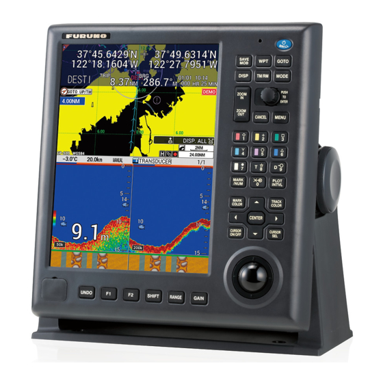
- Page 1 OPERATOR'S MANUAL GPS/WAAS COLOR CHART PLOTTER with FISH FINDER GP-3700F Model (Product Name: GPS PLOTTER/SOUNDER) www.furuno.com...
- Page 2 The paper used in this manual is elemental chlorine free. ・FURUNO Authorized Distributor/Dealer 9-52 Ashihara-cho, Nishinomiya, 662-8580, JAPAN A : APR 2017 Printed in Japan All rights reserved. Pub. No. OME-44920-A (YOTA ) GP-3700F 0 0 0 1 9 1 1 6 1 1 0...
-
Page 3: Important Notices
How to discard a used battery Some FURUNO products have a battery(ies). To see if your product has a battery, see the chap- ter on Maintenance. Follow the instructions below if a battery is used. Tape the + and - terminals of battery before disposal to prevent fire, heat generation caused by short circuit. -
Page 4: Safety Instructions
Electrical shock can result. noises, immediately turn off the power at the switchboard and Use the proper fuse. contact a FURUNO service techni- cian. Use of the wrong fuse can cause fire or electrical shock. - Page 5 To avoid electrical shock, do not A warning label is attached to the display remove cover. No user-serviceable Code No.: 100-236-233-10 unit. Do not remove the label. If the label is parts inside. missing or damaged, contact a FURUNO agent or dealer about replacement.
-
Page 6: Table Of Contents
TABLE OF CONTENTS FOREWORD ........................ix SYSTEM CONFIGURATION ..................xi OPERATIONAL OVERVIEW .................1-1 1.1 Controls........................1-1 1.1.1 Display unit..................... 1-1 1.1.2 Trackball control unit RCU-030 (option)............1-3 1.2 How to Turn the Power On/Off................... 1-3 1.3 How to Adjust the Brilliance of the Display and Panel ..........1-4 1.4 How to Select and Set a Display................ - Page 7 TABLE OF CONTENTS 3.4 How to Change Track Line Type ................3-9 3.4.1 How to change track line type for own ship ............3-9 3.4.2 How to change track line type for other ship ..........3-10 3.5 How to Select Track Plotting Method, Interval............3-10 3.5.1 How to select the track plotting method for own ship ........3-10 3.5.2...
- Page 8 TABLE OF CONTENTS 6.2 How to Edit Routes ....................6-5 6.2.1 How to insert waypoints ................. 6-5 6.2.2 How to delete waypoints from routes ............. 6-6 6.3 How to Delete Routes ....................6-6 6.4 How to Search Routes ....................6-6 6.5 How to Set the Speed to Use in TTG Calculation ............
- Page 9 TABLE OF CONTENTS 10.3.4 How to play back the data from the USB flash memory .......10-7 10.3.5 How to transfer the data from the USB flash memory ........10-8 10.4 Backup Data ......................10-9 10.4.1 How to backup the data automatically............10-9 10.4.2 How to backup the data manually ..............10-10 10.4.3 How to load the backup data..............10-11 10.5 Screenshot (Screen Capture).................10-12 10.6 How to Load the Data from Other Equipment ............10-13...
- Page 10 TABLE OF CONTENTS 11.20Echo Sounder Range Setting Menu ..............11-29 11.21Interpreting the Display..................11-30 12. AIS OPERATIONS ....................12-1 12.1 AIS Symbols......................12-1 12.2 How to Activate/Sleep Targets................. 12-2 12.3 AIS Tracks........................ 12-3 12.3.1 How to show/hide AIS tracks ............... 12-3 12.3.2 How to change the AIS symbol/track color or track line type .......
-
Page 11: Foreword
Please carefully read and follow the recommended procedures for operation and maintenance. Features The GP-3700F is a fully integrated GPS receiver, color video plotter, and color video fish finder. The system consists of a display unit, antenna unit, and transducer. The main features of the GP-3700F are as follows: •... - Page 12 FOREWORD Interference relief measures When another ship says it is receiving interference from your fish finder, change its working fre- quency or lower the transmission sound pressure level for the following equipment in the order shown. 1) Wideband fish finder 2) Fish finder with multiple frequencies 3) Fish finder with single frequency About future use...
-
Page 13: System Configuration
Submerged or in continuous set to NAV mode, only one of either GP-3700 or contact with sea water GP-3700F can be connected. Other Units Protected from the weather : Turn the GP-3700F power off before connecting to the NMEA2000 network. - Page 14 SYSTEM CONFIGURATION This page is intentionally left blank.
-
Page 15: Operational Overview
OPERATIONAL OVERVIEW Controls 1.1.1 Display unit When you correctly execute an operation, the display unit generates a beep. Invalid operation causes the unit to emit two beeps. If you do not need the key beep, deacti- vate the beep sound (see section 9.3). SAVE GOTO DISP... - Page 16 1. OPERATIONAL OVERVIEW Key, control Description • Short press at power-off: Turns the power on. POWER/BRILL • Short press at power-on: Opens the [BRILL] window. • Long press while powered: Turns the power off. Marks a man overboard position at own ship position or cursor po- sition.
-
Page 17: Trackball Control Unit Rcu-030 (Option)
How to Turn the Power On/Off Note: Turn the NMEA2000 network power on before turning the GP-3700F power on. Press the POWER/BRILL key at the top corner of the display unit to turn on the power. -
Page 18: How To Adjust The Brilliance Of The Display And Panel
To turn off the power, press and hold the POWER/BRILL key. The message "HOLD- ING THE POWER KEY WILL TURN THE GP-3700F OFF. POWER OFF IN 3 s." ap- pears then the countdown until power-off is started. Press and hold the POWER/ BRILL key until the indication "0 s"... -
Page 19: How To Select And Set A Display
1. OPERATIONAL OVERVIEW How to Select and Set a Display There are two base screens; plotter and echo sounder. You can display combination data with these two modes. See chapter 2 for plotter, chapter 11 for echo sounder. 1.4.1 How to select a display Press the DISP key consecutively to cycle through all the active displays. - Page 20 1. OPERATIONAL OVERVIEW 4. Select [1. DISPLAY 1 SETTING]. Split pattern Display screen Navigation/destination information List of split patterns 5. Select [SPLIT PATTERN]. 6. Select the split pattern from [LIST OF SPLIT PATTERNS]. The following steps are for [VERT SPLIT 1:1] (vertical split 1:1). 7.
-
Page 21: How To Skip A Display
1. OPERATIONAL OVERVIEW 11. Select [INFO1] or [INFO2] to display nav data in the NAV information box (see section 2.1.1, section 2.1.2). You can select the data to show with destination set and with no destination set (see section 1.4.4). No destination set With destination set [INFO1]... -
Page 22: How To Set The Navigation/Destination Information
1. OPERATIONAL OVERVIEW 1.4.4 How to set the navigation/destination information To set the navigation/destination information, do the following: 1. Press the MENU key to open the main menu. 2. Select [0. SYSTEM SETTING]. 3. Select [4. DISPLAY SETTING]. 4. Select [7. NAVIGATION INFO. 1 SETTING], [8. NAVIGATION INFO. 2 SET- TING], [9. -
Page 23: How To Switch The Active Screen
1. OPERATIONAL OVERVIEW 1.4.5 How to switch the active screen In the split screen for plotter or echo sounder, you can switch the active screen with the CURSOR ON/OFF key. Long-press the key to select the screen to make active. The active screen is circumscribed with an orange rectangle. - Page 24 1. OPERATIONAL OVERVIEW How to enter alphanumeric data The character entry window appears when you are required to enter alphanumeric da- ta. Press the CURSOR ON/OFF key to switch alphabet between upper case and lower case. Press the CURSOR ON/OFF key. 1.
-
Page 25: Mob Operations
1. OPERATIONAL OVERVIEW MOB Operations The MOB (Man OverBoard) mark denotes man overboard position. Press the SAVE MOB key to inscribe this mark should someone fall overboard. The following message appears. MOB POSITION SAVED. GOTO MOB? (CURRENT WAYPOINT WILL BE CANCELLED) CANCEL Select [RUN] to set the MOB mark position as the destination. -
Page 26: Function Keys
1. OPERATIONAL OVERVIEW Function Keys Some menu functions and menus can be assigned to the F1 or F2 key. This allows one-touch access to the assigned function or menu. The SHIFT, RANGE and GAIN keys can be available for function keys. Note: The F1 (or F2) key programmed with an echo sounder function is valid only on the echo sounder display or the echo sounder menu. - Page 27 1. OPERATIONAL OVERVIEW Function Description [EDIT MARK] Opens the [EDIT MARK] window. [DELETE MARK] Opens the [DELETE MARK] window. [INPUT MARK] Opens the [INPUT MARK] window. [EDIT TRACK] Opens the [EDIT TRACK] window. [DELETE TRACK] Opens the [DELETE TRACK] window. [DELETE ALL TRACK] Deletes all own ship tracks.
-
Page 28: Demo Mode
1. OPERATIONAL OVERVIEW Demo Mode The demo mode, available with both the plotter and echo sounder (connection of transducer is not required), provides simulated operation of this unit. All controls are operational. Use it in port or the like to acquaint yourself with the features of your unit. When the demo mode is active, the indication [DEMO] appears at the top right of the display. - Page 29 1. OPERATIONAL OVERVIEW 19. Select [MOVE FORWARD] or [FIGURE-8 TURN]. [MOVE FORWARD]: Track is traced according to the course set. [FIGURE-8 TURN]: Track is traced in figure-eight course. 20. Select [MODE INDICATOR]. 21. Select one of the following: [S: SIMULATOR]: Use the position data provided with the built-in simulator. [A: NORMAL POSITIONING]: Use GPS position data.
- Page 30 1. OPERATIONAL OVERVIEW This page is intentionally left blank. 1-16...
-
Page 31: Plotter Display Overview
PLOTTER DISPLAY OVERVIEW The plotter display can be shown on the full screen with or without the NAV information box, or in a two- or three-way horizontal or vertical split screen with the compass dis- play or the echo sounder display. Plotter Display 2.1.1 Plotter display layout... -
Page 32: Nav Information Box
2. PLOTTER DISPLAY OVERVIEW 2.1.2 NAV information box The NAV information box is displayed at the top or bottom of the screen. You can se- lect the data to show both when a destination is set and no destination set (see section 1.4.2, section 1.4.4). -
Page 33: Compass Display
2. PLOTTER DISPLAY OVERVIEW 2.1.3 Compass display The compass display, displayed at the top of the screen in a horizontal split 1:1 screen, provides steering information toward a destination. Range to destination waypoint Destination waypoint Estimated time of Time-to-go to arrival at destination destination waypoint... -
Page 34: Satellite Status/Location Display
(GEO) Green “- -” is shown for Receiver signal level these indications Bars show signal level. when the GP-3700F Satellites whose signal does not have the level is 40 or more are internal DGPS used to fix position. beacon receiver WAAS satellite (GEO) (option). -
Page 35: How To Use The Cursor
2. PLOTTER DISPLAY OVERVIEW How to Use the Cursor The cursor functions to select position for marks and waypoints, find position of an ob- ject, etc. You can select the cursor shape from crossing line and cross-hair. Crossing line Cross-hair To use the cursor, do the following: 1. -
Page 36: Orientation Mode
2. PLOTTER DISPLAY OVERVIEW When the cursor is ON: The range scale is enlarged or shrunk with the cursor position as center. The current range appears at the bottom right of the screen. The range value shows the distance between the left-side and right-side edges of the screen. Range (Unit: NM) 0.025 0.05... -
Page 37: How To Shift The Display
2. PLOTTER DISPLAY OVERVIEW 3. Select [2. NAVIGATOR SETUP]. Press Press [NAVIGATOR SETUP] menu: Page 1 [NAVIGATOR SETUP] menu: Page 2 4. Select [FREE UP ANGLE] on page 2. 5. Use the numeric keys to enter angle. 6. Press the DISP key to close the menu. How to Shift the Display The display can be shifted on the plotter display. -
Page 38: How To Measure The Range And Bearing Between Two Points
2. PLOTTER DISPLAY OVERVIEW How to Measure the Range and Bearing Between Two Points You can measure the range and bearing between any two points on the plotter dis- play. 1. If the cursor is displayed, press the CURSOR ON/OFF key to turn off the cursor. 2. -
Page 39: How To Change The Cursor Configuration
2. PLOTTER DISPLAY OVERVIEW How to Change the Cursor Configuration The cursor is available in four configurations; crossing line, circle, parallel index line, and diamond. When the cursor is turned on, the selected cursor is displayed with a focus on the cursor. When the cursor is turned off, the selected cursor is displayed with a focus on own ship mark. - Page 40 2. PLOTTER DISPLAY OVERVIEW amond. You can scale the diamond to match the size of your fishing net. The an- gles for casting net is displayed at the top left of the screen. To change the size of the diamond, see "How to change the size of the diamond cursor" on page 2-11. How to disable unnecessary cursors 1.
-
Page 41: Chart Icons
2. PLOTTER DISPLAY OVERVIEW How to change the size of the diamond cursor 1. Press the MENU key to open the main menu. 2. Select [8. PLOTTER DISPLAY SETTING]. 3. Select [4. SPECIAL CURSOR]. 4. Select [LENGTH A (OS TO CENTER)] in [DIAMOND CURSOR] on page 2. 5. - Page 42 2. PLOTTER DISPLAY OVERVIEW This page is intentionally left blank. 2-12...
-
Page 43: Track
TRACK Own ship track is plotted on the plotter display using position data fed from the built- in GPS receiver. When connecting with a ARPA-equipped radar or a TT-equipped ra- dar, other ship’s track can also be plotted. Headling line Course line TTM mark Target number... - Page 44 3. TRACK How to change the memory capacity for own track The default memory capacity for track is 30,000 points. If you don't need to record that many track points, you can change the memory capacity as shown below. If the num- ber of track points currently saved in the memory exceeds the track memory capacity, the oldest points over the capacity are erased.
-
Page 45: How To Show/Hide Other Ship's Tracks And Symbols
3. TRACK 3.1.2 How to show/hide other ship’s tracks and symbols Other ship’s (AIS, TT, GPS BUOY) tracks and symbols are shown or hidden individu- ally. 1. Press the MENU key to open the main menu. 2. Select [4. MARK/TRACK SETTING]. 3. -
Page 46: How To Show/Hide Drift Vector
3. TRACK 3.1.4 How to show/hide drift vector The drift vector (see "Simple calculation function for drift" on page 3-15) can be dis- played at every memory point on own ship track. 1. Press the MENU key to open the main menu. 2. -
Page 47: How To Show Track While Track Plotting Is Stopped
3. TRACK 2. To restart recording, press the PLOT INTVL key. The own ship mark changes from Note: Recording can also be stopped or restarted from the echo sounder display. 3.2.2 How to show track while track plotting is stopped You can show or hide own ship track on the plotter display while track plotting is stopped. -
Page 48: How To Change Track Color
3. TRACK How to Change Track Color Track color is available in red, yellow, green, light-blue, purple, blue, or white. It can be useful to change track color on a regular basis to discriminate between previous day’s track, etc. The track color for own ship can be changed automatically according to water temperature or depth. - Page 49 3. TRACK 3. Select [TRACK COLOR BY TEMP.] on page 2. 4. Select [RANGE]. 5. Set the temperature range desired for each color. For example, to paint the track red when the water temperature is higher than 68°F, do the following: 1) Select [RED].
-
Page 50: How To Automatically Change Track Color For Own Ship With Depth
3. TRACK 2. Select [4. MARK/TRACK SETTING]. 3. Select [TRACK COLOR BY TEMP.] on page 2. 4. Select [EV. 0.2] or [EV. 2.0]. 5. Press the DISP key to close the menu. 3.3.3 How to automatically change track color for own ship with depth The track color for own ship changes with depth when selecting [9. -
Page 51: How To Change Track Color For Other Ship
3. TRACK 1. Press the MENU key to open the main menu. 2. Select [4. MARK/TRACK SETTING]. 3. Select [TRACK COLOR BY DEPTH] on page 2. 4. Select [EV. 2], [EV. 20] or [EV. 200]. 5. Press the DISP key to close the menu. 3.3.4 How to change track color for other ship 1. -
Page 52: How To Change Track Line Type For Other Ship
3. TRACK 3.4.2 How to change track line type for other ship 1. Put the cursor on the target symbol to change its track line type. The selected tar- get data (see section 3.9) is displayed. 2. While the selected target data is displayed, press the TRACK COLOR key to show the [CHANGE TRACK COLOR] window. -
Page 53: How To Set The Track Plotting Intervals For Other Ship
3. TRACK 6. Press the numeric keys to enter time or range value. The setting range is 00M. 00S. to 99M. 59S. for time; 0.00 NM to 9.99 NM for range. When set [TIME IN- TERVAL] and [RANGE INTERVAL] to 0, the track is traced at intervals of 1 sec- ond. - Page 54 3. TRACK Note 1: The erased tracks cannot be restored. Note 2: The tracks in the internal memory that are set to [YES] on [DISPLAY OWN TRACK] in the [DISPLAY INTERNAL MEMORY] menu cannot be erased. Note 3: If the track is being automatically colored according to depth or water tem- perature, and the color in use just before selecting [8.
-
Page 55: How To Edit Own Ship Track
3. TRACK • [2. SET RNG]: Select the starting point of the area Starting point to erase. Then select the ending point of the area to erase. The selected area is framed in a white Cursor (Ending triangle with gray border. Go to step 7. point) 7. -
Page 56: How To Display Own Ship Information
3. TRACK 6. Do one of the following: Squares (memory points) appear on the track. • [1. BTWN 2PTS.]: Select the starting memory point to edit. Then select the end- ing memory point to edit. • [2. SET RNG]: Select the starting point of the area to edit. Then select the end- ing point of the area to edit. -
Page 57: Detailed Information
3. TRACK 3.8.2 Detailed information 1. Press the CURSOR ON/OFF key to turn on the cursor. 2. Put the cursor on the own ship mark then push the ENTER knob to display the detailed information. “- -” is displayed when no data is input. - Page 58 3. TRACK Note: If other ship information does not appear when putting the cursor on the target symbol, do the following: 1) Press the MENU key to open the main menu. 2) Select [0. SYSTEM SETTING]. 3) Select [1. DISPLAY FORMAT]. 4) Select [OTHR SHIP INFO DISP.] on page 5.
-
Page 59: How To Change The Size Of The Target Number
3. TRACK Note: You can display the detailed information by putting the cursor on the GPS buoy symbol then pushing the ENTER knob. • TRACK COLOR key: Displays the [CHANGE TRACK COLOR ID (XX)] win- dow. Change the color and line type for the selected GPS buoy (see section 3.3 and section 3.4). -
Page 60: How To Erase Other Ship Track
3. TRACK 3.11 How to Erase Other Ship Track To erase other ship track, do the following: 1. Press the MENU key to open the main menu. 2. Select [5. MARK/TRACK EDIT/DELETE]. 3. Select [6. DELETE OTHER SHIPS’ TRACK]. 4. Select [SEL. METH.]. 5. -
Page 61: Marks, Lines
MARKS, LINES Marks are useful for denoting important points such as a good fishing spot. 30,000 marks can be entered. Marks can be inscribed in 12 shapes or with a numeral, and seven colors. Marks can be connected with lines. Marks can be entered from the echo sounder display. -
Page 62: How To Set Mark Size
4. MARKS, LINES 4.1.2 How to set mark size You can select the mark size as follows: 1. Press the MENU key to open the main menu. 2. Select [4. MARK/TRACK SETTING]. 3. Select [MARK SIZE] on page 1. 4. Select the mark size. [LARGE] [LARGE WITH DOT] [SMALL]... -
Page 63: How To Set Fish Type For Marks
4. MARKS, LINES 4.1.4 How to set fish type for marks Fish type can be assigned to marks. Marks can be shown or hidden depending on fish type with the mark filter function (see section 4.8). 1. Press the MARK COLOR key to show the [CHANGE MARK COLOR] window. Note: This window automatically closes when there is no operation for 10 sec- onds. -
Page 64: How To Enter Marks At The Cursor Position
4. MARKS, LINES 4.2.2 How to enter marks at the cursor position 1. Press the CURSOR ON/OFF key to turn on the cursor. 2. Put the cursor on the position where you want to enter a mark. 3. Press a numeric key among 1 to 8. 4 key: 2 key: 1 key:... -
Page 65: How To Enter Lines
4. MARKS, LINES 11. Select a shape among 12 symbols and figures of 0 to 9. Top: Use the numeric keys to set. Bottom: Use the ENTER knob to set. 12. Select [LINE TYPE]. 13. Press the applicable numeric key to select a line type. When selecting 1, 2, 3 or 4, marks are connected with a line. -
Page 66: How To Erase Marks, Lines
4. MARKS, LINES How to Erase Marks, Lines Marks can be erased directly on the screen or from the menu, and five methods of era- sure are available from the menu: • [1. CURSOR]: Erases mark, line selected with the cursor. •... -
Page 67: How To Edit Marks, Lines
4. MARKS, LINES 5. Press the applicable numeric key to select the method for erasing marks and lines. For [1. CURSOR] or [2. SET RNG], go to step 6. For [3. WITHIN RNG], [4. OUT OF RNG], or [5.ALL], go to step 7. 6. -
Page 68: How To Undo Or Redo Mark/Line Operation
4. MARKS, LINES 3. Select [1. EDIT MARK]. 4. Select [SEL. METH.]. 5. Press the applicable numeric key to select the method for editing range. For [1. CURSOR] or [2. SET RNG], go to step 6. For [3. WITHIN RNG] or [4. OUT OF RNG], go to step 7. -
Page 69: How To Show Mark Information
4. MARKS, LINES How to Show Mark Information Mark information can be shown on the screen. Simple information 1. Press the CURSOR ON/OFF key to turn on the cursor. 2. Put the cursor on the mark to find its information. Data (latitude and longitude po- sition, water temperature, depth) for the mark is shown on the screen. -
Page 70: Mark Filter
4. MARKS, LINES Mark Filter Marks can be shown or hidden according to mark attribution. How to set object and content for the mark filter 1. Push the ENTER knob. The mark filter at the bottom right of the screen is high- lighted. - Page 71 4. MARKS, LINES Object for filter Option of content to filter Meaning [COMP] [DISP. ALL], [MUD], [SAND], Displays marks for the select- [GRAVEL],[ROCK] ed bottom hardness. Re- quires the information for bottom hardness (see "De- tailed information" on page 4- [TEMP] [DISP.
- Page 72 4. MARKS, LINES How to turn on or off an object to filter 1. Press the MENU key to open the main menu. 2. Select [4. MARK/TRACK SETTING]. 3. Display [DISPLAY MARK FILTER] on page 4. 4. Select any one from [FISH TYPE] to [MULTI]. 5.
- Page 73 4. MARKS, LINES 5. Set the fish type (see "How to enter alphanumeric data" on page 1-10). Select [ENTER] to go back to [MARK FILTER FISH TYPE SETTING] on page 5. The fish type set is displayed on the right side of the [TYPE OF FISH 1](to 10) item. 6.
- Page 74 4. MARKS, LINES This page is intentionally left blank. 4-14...
-
Page 75: Waypoints
WAYPOINTS In navigation terminology, a waypoint is a particular geographical location on a voyage whether it be a starting, intermediate or destination point. A waypoint is the simplest piece of information your equipment requires to get you to a destination, in the shortest distance possible. -
Page 76: How To Enter Waypoints By Manually Entering Latitude And Longitude Position
5. WAYPOINTS Note: The [WAYPOINTS LIST] window closes automatically when there is no op- eration for 10 seconds. 4. Press the numeric keys to enter the name of the waypoint (six digits) then push the ENTER knob. The currently indicated waypoint number is the youngest num- ber among the unused numbers. - Page 77 5. WAYPOINTS 3. Select [1. WAYPOINTS LIST]. 4. Press the WPT key or ENTER knob to show the [EDIT WPT NAME] window. Note: Push the ENTER knob after selecting a blank line. 5. Select [COORDINATE]. 6. Select [LATITUDE/LONGITUDE]. 7. Select [LATITUDE]. 8.
-
Page 78: How To Enter Waypoints By Range And Bearing
5. WAYPOINTS 12. Set the waypoint name (see "How to enter alphanumeric data" on page 1-10). 13. Select [MARK COLOR]. 14. Select the mark color. 15. Select [MARK SHAPE]. 16. Select the mark shape. 17. Select [MARK DISPLAY]. 18. Select [YES] or [NO]. [YES]: Shows the waypoint mark on the plotter display. -
Page 79: How To Enter Waypoints By Loran A Or Loran C Lops
5. WAYPOINTS 6. Select [RANGE/BEARING]. When selecting [RANGE/BEARING] in [COORDINATE], [DISTANCE] and [BRG] are displayed here. 7. Select [DISTANCE]. 8. Press the numeric keys to enter the range from own ship to the waypoint. 9. Select [BRG]. 10. Press the numeric keys to enter the bearing from own ship to the waypoint. 11. -
Page 80: How To Enter Waypoints By Decca Lops
5. WAYPOINTS 8. Select [1. WAYPOINTS LIST]. 9. Press the WPT key or ENTER knob to show the [EDIT WPT NAME] window. Note: Push the ENTER knob after selecting a blank line. 10. Select [COORDINATE]. 11. Select [TIME DIFFERENCE]. When selecting [TIME DIFFERENCE] in [COORDINATE], [TME ADJ1] and [TME ADJ2] are displayed here. -
Page 81: How To Edit Waypoints
5. WAYPOINTS 11. Select [TIME DIFFERENCE]. When selecting [TIME DIFFERENCE] in [COORDINATE], [LANE 1] and [LANE 2] are displayed here. 12. Select [LANE 1]. 13. Press the numeric keys to enter the value for [LANE 1]. Enter the alphabet of the lane by pressing applicable numeric key, referring to the following: 1 key: A 2 key: B... -
Page 82: How To Erase A Waypoint
5. WAYPOINTS How to Erase a Waypoint A waypoint can be erased with the cursor or from the waypoints list. How to erase a waypoint with the cursor 1. Press the CURSOR ON/OFF key to display the cursor. 2. Put the cursor on the waypoint to erase. 3. -
Page 83: How To Set Speed To Use In Ttg Calculation
5. WAYPOINTS How to search by waypoint name 1. Press the MENU key to open the main menu. 2. Select [1. ROUTES/WAYPOINTS LIST]. 3. Select [1. WAYPOINTS LIST]. 4. Select [SEARCH] to show the [SEARCH] window. 5. Enter the first three characters of the waypoint name (see "How to enter alphanu- meric data"... -
Page 84: How To Change Waypoint Mark Size
5. WAYPOINTS How to Change Waypoint Mark Size You can change the size of all waypoints to small or large, or turn them off. 1. Press the MENU key to open the main menu. 2. Select [7. COAST LINE SETTING]. 3. -
Page 85: Routes
ROUTES Often a trip from one place to another involves several course changes, requiring a series of route points (waypoints) which you navigate to, one after another. The se- quence of waypoints leading to the ultimate destination is called a route. How to Create Routes You can store up to 200 routes and a route may contain a maximum of 100 route points. - Page 86 6. ROUTES 7. Select [COMMENT]. 8. Enter the comment (see "How to enter alphanumeric data" on page 1-10). 9. Select [RUN] to show [RTE TRN PT LIST]. 10. Push the ENTER knob to move the cursor to the waypoints list. For multiple pages, press ◄...
-
Page 87: How To Create Track-Based Routes Using Own Ship Position
6. ROUTES 13. Press the MENU key twice to return to [ROUTES LIST]. The total distance, num- ber of waypoints, ETA and TTG are shown. Number of waypoints Total distance from first waypoint to final waypoint Preview for final waypoint Estimated time of arrival Time to go To set the route as your destination, press the GOTO key. -
Page 88: How To Create Routes With Selected Tracks
6. ROUTES 2) Press the WPT key where you want to register the current own ship position as the waypoint. The message "ADDED WAYPOINT xxxxxx TO ROUTE XXXXXX." appears. 3) Press the WPT key where you want to change the course. The message same with the one in step 2 appears. -
Page 89: How To Edit Routes
6. ROUTES 9. Press the numeric keys to set the angle filtered. 10. Select [RUN CONV.]. The number of points converted to waypoints is displayed. • WPT key: If you want to convert a filtered memory point to a waypoint, select the memory point then press the WPT key. -
Page 90: How To Delete Waypoints From Routes
6. ROUTES 8. Press the DISP key to close the menu. 6.2.2 How to delete waypoints from routes 1. Press the MENU key to open the main menu. 2. Select [1. ROUTES/WAYPOINTS LIST]. 3. Select [2. ROUTES LIST]. 4. Select the route to process, and the [ROUTE NAME/ENTER COMMENT] window appears. -
Page 91: How To Set The Speed To Use In Ttg Calculation
6. ROUTES How to search by route name 1. Press the MENU key to open the main menu. 2. Select [1. ROUTES/WAYPOINTS LIST]. 3. Select [2. ROUTES LIST]. 4. Select [SEARCH] to show the [SEARCH] window. 5. Enter the first three characters of the route name (see "How to enter alphanumeric data"... - Page 92 6. ROUTES This page is intentionally left blank.
-
Page 93: Destination
DESTINATION This chapter shows you how to get to a desired destination, using “quick points,” way- points, and routes. How to Go to a Quick Point The quick point feature allows you to navigate to point(s) without retaining the data in the internal memory. - Page 94 7. DESTINATION How to navigate to a single quick point 1. Set the quick point entry method to [ONE POINT], referring to "How to select the quick point entry method" on page 7-1. 2. Show the plotter display with NAV information (see section 1.4.2 and section 2.1.2).
- Page 95 7. DESTINATION How to navigate a quick point route 1. Set the quick point entry method to [100 POINTS], referring to "How to select the quick point entry method" on page 7-1. 2. Show the plotter display with NAV information (see section 1.4.2 and section 2.1.2).
-
Page 96: How To Set A Waypoint As Destination
7. DESTINATION How to Set a Waypoint as Destination There are four methods to set a waypoint as destination. • Set a waypoint as destination on the plotter display. • Set a waypoint as destination from the waypoints list. • Set a waypoint as destination with a waypoint number. •... - Page 97 7. DESTINATION Note: The [SELECT WP] window closes automatically when there is no operation for 10 seconds. 3. Press the numeric keys to enter the waypoint number to set as the destination then push the ENTER knob. A light-blue line connects the own ship with the destination. When selecting [DIS- TANCE TO WAYPOINT] and [BEARING TO WAYPOINT] for destination information, range and bearing from own ship to the destination appear on the NAV information box.
-
Page 98: How To Follow Routes
7. DESTINATION How to Follow Routes How to set a route as destination 1. Press the MENU key to open the main menu. 2. Select [1. ROUTES/WAYPOINTS LIST]. 3. Select [2. ROUTES LIST]. 4. Select the route to set as destination then press the CURSOR ON/OFF key to switch the direction to follow the route. - Page 99 7. DESTINATION 4. Select the route to change. The [ROUTE NAME/ENTER COMMENT] window ap- pears. 5. Select [RUN] to display [RTE TRN PT LIST]. 6. Select the waypoint to skip then press the CURSOR ON/OFF key. "-" appears in [DISTANCE], [TTG] and a field before [WPT]. Waypoint to skip Note: To restore a waypoint, select it then press the CURSOR ON/ OFF key.
-
Page 100: How To Stop Navigation
7. DESTINATION How to Stop Navigation 1. Press the GOTO key to show the following message. XXXXXX SET AS A DESTINATION. CANCEL DESTINATION? CANCEL 2. Select [RUN] to stop navigation. -
Page 101: Alarms
ALARMS This unit has 20 alarms which alert you with audio and visual alarms. • Arrival • Anchor watch • Route • Cross-track error (XTE) • Border • Intrusion point • Ship speed • Trip range • AIS auto activation •... -
Page 102: How To Turn The Audio Alarm On/Off
8. ALARMS How to Turn the Audio Alarm On/Off The audio alarm sounds whenever an alarm setting is violated. You can enable or dis- able the audio alarm as follows: 1. Press the MENU key to open the main menu. 2. -
Page 103: Arrival, Anchor Watch Alarm
8. ALARMS Arrival, Anchor Watch Alarm The arrival alarm informs you that your vessel is approaching a destination waypoint. The area that defines an arrival zone is that of a circle which you approach from the outside of the circle. The alarm will be released if your vessel enters the circle. When the arrival alarm is active, a red dashed circle marks the arrival alarm area. -
Page 104: Route Alarm
8. ALARMS Route Alarm The route alarm sets an anchor watch alarm on each route point (waypoint) in the route in use. When your vessel goes out of the anchor watch alarm range at a route point, the audio alarm sounds. To use this alarm, [ANCHOR WATCH ALARM] must be set to [ON] (see section 8.2). -
Page 105: Intrusion Point Alarm
8. ALARMS 3. Select [XTE/BORDER ALARM] on page 1. 4. Select [OFF COURSE] or [INTRUSION]. 5. Select [ALARM RANGE]. 6. Press the numeric keys to set the alarm range (setting range: 0.001 to 9.999 NM). 7. Press the DISP key to close the menu. To deactivate an alarm, select [OFF] at step 4. -
Page 106: Trip Range Alarm
8. ALARMS Trip Range Alarm The trip range alarm informs you when you have traveled a certain distance. 1. Press the MENU key to open the main menu. 2. Select [6. ALARM SETTINGS]. 3. Select [TRIP RANGE ALARM] on page 1. 4. -
Page 107: Shear Alarm
8. ALARMS 3. Select [WATER TEMP. ALARM] on page 2. 4. Select [WITHIN RANGE] or [OUT OF RANGE]. 5. Select [LOWEST WATER TEMP.]. 6. Press the numeric keys to enter the minimum temperature (setting range: -99.9 to +99.9°F). 7. Select [HIGHEST WATER TEMP.]. 8. -
Page 108: Depth Alarm
8. ALARMS 8.10 Depth Alarm The depth alarm sounds when the bottom echo is within the alarm range set. 1. Press the MENU key to open the main menu. 2. Select [6. ALARM SETTINGS]. 3. Select [DEPTH ALARM] on page 3. 4. -
Page 109: Other Functions
OTHER FUNCTIONS This chapter describes the various options which allow you to set up your unit to suit your needs. [COAST LINE SETTING] Menu The [COAST LINE SETTING] menu has three menus: [COAST LINE DETAIL SET- TING], [CONTOUR LINE FINE RNG SETTINGS] and [INDIVIDUAL CONTOUR LINE SETTINGS]. - Page 110 9. OTHER FUNCTIONS [DISPLAY WAYPOINT]: Turns waypoint on or off and selects size to large or small (see section 5.7). [WPT NAME DISPLAY]: Turns waypoint name on or off and selects size to large or small on the plotter display. The waypoint name is displayed in the color same as way- point mark.
- Page 111 [COAST LINE DETAIL SETTING] menu: Page 3 [CHANGE CHARTS]: Selects chart type from [VECTOR], [FISHING], [C-MAP], or [NAVIONICS]. [VECTOR]: Navigational chart (data by FURUNO). [FISHING]: Fishing chart that shows detailed depth contours. [C-MAP]: Navigational chart. Select this when using C-MAP chart data.
-
Page 112: How To Display Depth Contour In Detail
9. OTHER FUNCTIONS Note: Depth contours for [FISHING] are drawn differently from navigational chart data (bathymetric chart data). Fishing chart does not have the latest shallow information, so select [VECTOR] when sailing into/out of port or sailing along a coastline. 9.1.2 How to display depth contour in detail You can set the level of detail between depth contour lines by the distance between... -
Page 113: Plotter Display Setting] Menu
9. OTHER FUNCTIONS [PLOTTER DISPLAY SETTING] Menu This section describes the [PLOTTER DISPLAY SETTING] menu. See section 2.1.4 for the [SATTELITE STATUS/LOCATION] menu, section 2.7 for the [SPECIAL CUR- SOR] menu. 9.2.1 How to set TD display To display own ship position in TDs in the NAV information box, follow the procedure below. - Page 114 9. OTHER FUNCTIONS 4. Select [LORAN C STA. COMB.]. 5. Press the numeric keys to set the GRI code referring to the [GRI CODE LIST] at the bottom of the window. For example, press the 1, 0 keys in order for GRI9970. [RCH CODE LIST] for GRI9970 is displayed at the bottom of the window.
- Page 115 9. OTHER FUNCTIONS How to display position in DECCA TDs 1. Press the MENU key to open the main menu. 2. Select [8. PLOTTER DISPLAY SETTING]. 3. Select [3. LORAN/DECCA SETTING]. 4. Select [DECCA CHAIN]. 5. Press the numeric keys to enter chain number (01 to 48). [RCH LST] is displayed at the bottom of the window.
-
Page 116: How To Set Range For Plotter Display
9. OTHER FUNCTIONS 9.2.2 How to set range for plotter display You can select the plotter display ranges you wish to use. After selecting the ranges desired, change the range with the ZOOM IN or ZOOM OUT key to activate range set- tings. - Page 117 9. OTHER FUNCTIONS [DISPLAY FORMAT] menu: Page 1 [LANGUAGE]: Selects language to use. [KEY BEEP]: Enables or disables the beep that sounds each time a key is operated. [SPEED SENSOR]: Selects the source of speed data from [INTERNAL GPS], [NMEA FOR SOG], [NMEA FOR STW] or [FISH FINDER].
- Page 118 9. OTHER FUNCTIONS [PITCH OFFSET]: Sets the offset value for pitch. [ROLL OFFSET]: Sets the offset value for roll. [DISPLAY FORMAT] menu: Page 2 [LAT./LON. GRID]: Selects the display format for latitude and longitude from [DD°MM.MM’], [DD°MM.MMM’], [DD°MM.MMMM’], or [DD°MM’SS.S’’]. [RANGE/SPEED]: Selects the unit for range and speed from [NM, kn], [km, km/h] or [SM, mph].
- Page 119 9. OTHER FUNCTIONS [DISP. HDG MARKER]: Turns the heading marker on or off. (Heading data is re- quired.) [SHOW] shows white heading marker to the edge of the screen. [VECTOR] shows white vector of the length proportional to speed. The length does not change when switching the chart scale.
- Page 120 9. OTHER FUNCTIONS [WAYPOINT STATUS]: Turns the waypoint status icon on or off on the plotter display. This icon (default: ) shows the current shape and color of waypoints. [WAYPOINT INFORMATION]: Turns the waypoint data on or off. When [SHOW] is se- lected, place the cursor on a waypoint to show the waypoint data box.
- Page 121 [WITH]: Restarts the course from the position where NAV mode is restored. [NO]: Does not restart the course, regardless of NAV mode. Note: This function is available with connection of a FURUNO autopilot. See the Op- erator’s Manual of the autopilot for details.
- Page 122 9. OTHER FUNCTIONS [DISPLAY OS DRIFT VECTOR]: Turns the drift vector on or off on the own ship mark (see "Simple calculation function for drift" on page 3-15). [OS CURR. VECTOR DISP]: Turns the current vector on or off on the own ship mark. Requires current data received from NMEA0183.
-
Page 123: Navigator Setup] Menu
9. OTHER FUNCTIONS [NAVIGATOR SETUP] Menu The [NAVIGATOR SETUP] menu selects the source of navigation data and sets up the built-in GPS receiver. 1. Press the MENU key to open the main menu. 2. Select [0. SYSTEM SETTING]. 3. Select [2. NAVIGATOR SETUP] which has two pages. 4. - Page 124 (3D requires four or more satellites.) [DGPS/SBAS]: Selects the position-fixing method from [DGPS], [SBAS] or [AUTO- MATIC]. (For SBAS, see "WHAT IS SBAS?" on page AP-13.) The GP-3700F requires the optional DGPS beacon receiver to fix position by DGPS. [AUTOMATIC] fixes po- sition by SBAS when DGPS correction data is not available.
- Page 125 9. OTHER FUNCTIONS Select [AUTOMATIC]. [NAVIGATOR SETUP] menu: Page 2 [DGPS BEACON STATION]: DGPS reference station can be searched automatically or manually. For manual search, select [MANUAL] here, and set the frequency of the DGPS reference station in the item [FREQUENCY SETTINGS]. [FREQUENCY SETTINGS]: When selecting [MANUAL] in [DGPS BEACON STA- TION], set the frequency of the DGPS reference station which is the nearest to own ship.
-
Page 126: Input/Output Port Setting] Menu
9. OTHER FUNCTIONS [SBAS MAN. SAT. SET.]: When selecting [MANUAL] in [SBAS SATELLITE SEL.], manually enter the GEO satellite number (120 to 138). [DISABLE SATELLITE(SBAS)], [DISABLE SATELLITE(QZSS)]: Every GPS satellite is broadcasting abnormal satellite number(s) in its Almanac, which contains general orbital data about all GPS satellites. - Page 127 9. OTHER FUNCTIONS 4. Select [1. PORT 1 SETTING], [3. PORT 2 SETTING] or [5. PORT 3 SETTING]. 5. Select an item to change. [CONNECTED DEVICE]: Selects the device connected to the port 1 (or 2, 3) from [NORMAL], [RADIO EQUIPMENT], [AIS], [GPS BUOY], [AUTO PILOT] or [RT- CM].
-
Page 128: How To Set The Ethernet
9. OTHER FUNCTIONS 8. Select [2. PORT 1 OUTPUT SENTENCE], [4. PORT 2 OUTPUT SENTENCE] or [6. PORT 3 OUTPUT SENTENCE]. Page 1 Page 2 9. Select the sentence to change. 10. Select [OUTPUT] or [NO OUTPUT]. 11. Press the DISP key to close the menu. 9.5.2 How to set the Ethernet 1. -
Page 129: How To Display The Information For Nmea2000 Equipment
9. OTHER FUNCTIONS 9.5.3 How to display the information for NMEA2000 equipment 1. Press the MENU key to open the main menu. 2. Select [0. SYSTEM SETTING]. 3. Select [5. INPUT/OUTPUT PORT SETTING]. 4. Select [8. SHOW NMEA2000 DEVICES]. SC-50 12345-67890 SC-30 98765-43210... -
Page 130: Test & Memory Clear] Menu
9. OTHER FUNCTIONS 4. Select [9. NMEA2000 PGN]. Page 1 Page 2 5. Select a PGN to change. 6. Select [OUTPUT] or [NO OUTPUT]. 7. Press the DISP key to close the menu. [TEST & MEMORY CLEAR] Menu This menu provides the diagnostic test, memory clearing, password setting, and track- ball sensitivity. -
Page 131: How To Disable The Password
9. OTHER FUNCTIONS 4. Select [6. SET PASSWORD]. 5. Use the numeric keys to enter the password with four digits. 6. Enter the password set at step 5 again. The message "PASSWORD IS DECID- ED. THE PASSWORD WILL BE EFFECTIVE FROM NEXT TIME." appears. 7. -
Page 132: Line Monitor
9. OTHER FUNCTIONS 6. Select [HIGH], [MEDIUM] or [LOW]. [HIGH]: The cursor responds quickly when rotating the trackball. [MEDIUM]: The cursor responds at the intermediate speed between [HIGH] and [LOW]. [LOW]: The cursor moves slowly when rotating the trackball. When the cursor moves because of the heavy hull vibration without rotating the trackball, select [MEDIUM]. - Page 133 9. OTHER FUNCTIONS 4. Select a serial port to display RX/TX sentences. To stop showing the sentences, press the 0 key. The indication "PLAYING" at the top of the screen changes to "TEMP STOP DISP". To re-display the sentences, press the 0 key. Example: [1.
- Page 134 9. OTHER FUNCTIONS This page is intentionally left blank. 9-26...
-
Page 135: How To Record, Play Back Data
10. HOW TO RECORD, PLAY BACK DATA This chapter provides information necessary for recording and playing back data, and uploading and downloading data to (from) a USB flash memory. 10.1 Data Recording Data can be recorded in the “working memory”. The working memory stores data such as tracks, marks, lines, routes, waypoints, setting data. - Page 136 10. HOW TO RECORD, PLAY BACK DATA 2. Select [3. USB/INTERNAL MEMORY MANAGEMENT]. 3. Select [3. INTERNAL MEMORY RECORDING]. 4. Select an item to save. 5. Select [YES]. 6. Repeat steps 4 and 5 to save other items. 7. Select one of 10 memory blocks from [DATA SELECTION] to show the [COM- MENT] window.
-
Page 137: How To Display The Data Stored In The Internal Memory
10. HOW TO RECORD, PLAY BACK DATA 10.2.2 How to display the data stored in the internal memory Tracks, marks and lines stored in the internal memory can be displayed on the screen. 1. Press the MENU key to open the main menu. 2. -
Page 138: How To Play Back Data From The Internal Memory
10. HOW TO RECORD, PLAY BACK DATA 10.2.3 How to play back data from the internal memory Data in the internal memory can be loaded to the working memory and played back on the screen. However, loaded waypoint/route and setting data will replace current data or add to current data, depending on play back method. -
Page 139: How To Delete Data From The Internal Memory
10. HOW TO RECORD, PLAY BACK DATA 10.2.4 How to delete data from the internal memory To delete data from the internal memory, do the following: 1. Press the MENU key to open the main menu. 2. Select [3. USB/INTERNAL MEMORY MANAGEMENT]. 3. -
Page 140: How To Safely Remove A Usb Flash Memory
10. HOW TO RECORD, PLAY BACK DATA 10.3.2 How to safely remove a USB flash memory CAUTION Do the following when removing a USB connection device such as a USB flash memory. The data stored in the USB flash memory may become corrupted if the memory is not removed correctly. 1. -
Page 141: How To Play Back The Data From The Usb Flash Memory
10. HOW TO RECORD, PLAY BACK DATA 10. To save the data in the working memory, select [RUN DATA] from [DATA SELEC- TION]. To save the data in the internal memory, select one of [1:XXXXXXXXXX] to [0:XXXXXXXXXX] (XXXXXXXXXX: file name) from [DATA SELECTION]. The [FILE NAME] window appears. -
Page 142: How To Transfer The Data From The Usb Flash Memory
10. HOW TO RECORD, PLAY BACK DATA 6. Select [ADD] or [OVERWRITE] depending on the item selected at step 5. [ADD]: Adds the selected data to the current display data. [OVERWRITE]: Overwrites the current display data. Note: When setting [RECORD MARK/TRACK] to [ADD], the selected data can not be added if the memory capacity is reached (30,000). -
Page 143: Backup Data
10. HOW TO RECORD, PLAY BACK DATA 5. Select an item to transfer. 6. Select [YES]. 7. Repeat step 5 and step 6 to transfer other data. 8. Select [SEL DATUM]. 9. Select [WGS-84] or [TOKYO]. 10. Select the file to transfer from [DATA SELECTION]. The [COMMENT] window ap- pears. -
Page 144: How To Backup The Data Manually
10. HOW TO RECORD, PLAY BACK DATA How to backup the data to the internal memory automatically 1. Press the MENU key to open the main menu. 2. Select [3. USB/INTERNAL MEMORY MANAGEMENT]. 3. Select [7. AUTO BACKUP]. 4. Select [INTERNAL MEMORY]. 5. -
Page 145: How To Load The Backup Data
10. HOW TO RECORD, PLAY BACK DATA 4. Select [2. SAVE TO INTERNAL MEMORY]. The following message appears. OVERWRITE BACKUP DATA ALREADY IN INTERNAL MEMORY. ARE YOU SURE? 5. Select [RUN] to backup the data. The message "TRANSFERRING. PLEASE WAIT." appears. 6. -
Page 146: Screenshot (Screen Capture)
10. HOW TO RECORD, PLAY BACK DATA 10.5 Screenshot (Screen Capture) This system has a screen capture function. The screenshot data is saved in the inter- nal memory. Also, you can transfer the data to a USB flash memory as follows: 1. -
Page 147: How To Load The Data From Other Equipment
Note 2: When using a commercial USB floppy drive, insert a floppy disk to the drive before connecting the drive to the GP-3700F. When changing a floppy disk, reconnect the drive to the GP-3700F. 1. Connect a USB device, in which the data to load are saved, in the USB drive. - Page 148 10. HOW TO RECORD, PLAY BACK DATA 8. Repeat steps 6 and 7 to load other items. 9. Select [SEL DATUM]. 10. Select [WGS-84] or [TOKYO]. 11. Select the file to load from [DATA SELECTION]. The confirmation message ap- pears. 12.
-
Page 149: 11. Echo Sounder
11. ECHO SOUNDER 11.1 How the Echo Sounder Operates The echo sounder calculates the distance between its transducer and underwater ob- jects like fish, lake bottom or seabed. The results are shown in different colors or shades of gray according to echo strength. The ultrasonic waves transmitted through water move at a constant speed of approx- imately 4800 feet (1500 meters) per second. -
Page 150: Single Frequency Display (50 Khz Or 200 Khz)
11. ECHO SOUNDER 11.2.1 Single frequency display (50 kHz or 200 kHz) Low frequency (50 kHz) The sounder uses ultrasonic signals to detect bottom conditions. The lower the frequency of the signal, the High wider the detection area. Therefore, the 50 kHz frequen- freq. -
Page 151: Dual Frequency Display
11. ECHO SOUNDER 11.2.2 Dual frequency display The dual frequency display provides both low and high frequency pictures. For vertical split screen, the low frequency picture (50 kHz) is displayed on the left half, the high frequency picture (200 kHz) on the right half. For horizontal split screen, the low fre- quency picture (50 kHz) is displayed on the top half, the high frequency picture (200 kHz) on the bottom half. -
Page 152: Bottom Zoom Display (50 Khz Or 200 Khz)
11. ECHO SOUNDER 11.2.4 Bottom zoom display (50 kHz or 200 kHz) The bottom-zoom display expands bottom and bottom fish echoes by the zoom range selected on the menu (see section 11.20). This mode is useful for determining bottom contour. When the bottom depth increases, the display automatically shifts to keep the bottom echo at the lower part of the screen. -
Page 153: Bottom Discrimination Display (50 Khz Or 200 Khz)
11. ECHO SOUNDER 11.2.6 Bottom discrimination display (50 kHz or 200 kHz) The bottom discrimination (seabed composition) display shows the normal display as the right half, the left half of the display is split in half horizontally with the bottom zoom display on the upper half and the bottom discrimination display on the lower half. -
Page 154: Mix Display
11. ECHO SOUNDER Peak hold display The peak hold function shows “normal” A-scope display plus peak-hold amplitude pic- ture in dots. The peak hold is cleared every five seconds. Note: When the strong echo appears after weak echo at the same depth, the peak- hold amplitude picture is updated. -
Page 155: Plotter/Echo Sounder Display
11. ECHO SOUNDER Low frequency High frequency (50 kHz) (200 kHz) Green Blue Yellow Green Reddish- Reddish- brown brown Orange These echoes are Discriminator likely to be small fish. Blue Yellow Displayed in blue since high frequency echo is weaker. Reddish-brown Reddish-brown Blue... -
Page 156: Automatic Echo Sounder Operation
11. ECHO SOUNDER 11.3 Automatic Echo Sounder Operation The automatic fish finder function automatically adjusts the gain, clutter, and range, to free you to do other tasks. The main features of the automatic mode are as shown be- low. • Range is adjusted automatically to show the bottom echo. •... -
Page 157: Manual Echo Sounder Operation
11. ECHO SOUNDER Note 1: The [BTM DISP RNG] window closes automatically when there is no op- eration for 10 seconds. Note 2: The maximum value for upper limit and the minimum value for lower limit vary depending on the setting value. The setting value for upper limit plus 15 equals the minimum value for lower limit. -
Page 158: How To Select The Display Range
11. ECHO SOUNDER 11.4.2 How to select the display range The basic range may be selected with the RANGE key, from the eight ranges shown in the table below. (These eight ranges may be programmed as desired. For details, see section 11.20.) Basic range Unit 1000... -
Page 159: How To Adjust The Gain
11. ECHO SOUNDER 11.4.4 How to adjust the gain The gain controls how echoes of different strengths are displayed. Set the gain to show a slight amount of noise on the screen. Increase the gain for greater depths and lower the gain for shallow waters. CAUTION Use the proper gain setting. -
Page 160: How To Measure Depth, Time Between Locations
11. ECHO SOUNDER 11.5 How to Measure Depth, Time Between Locations You can measure the depth to an object with the VRM. Also, you can measure the time from the right edge to a location. For example, you can measure how many minutes ago an echo appeared. -
Page 161: How To Enter A Mark On The Display
11. ECHO SOUNDER 11.6 How to Enter a Mark on the Display You can mark the geographical location of a school of fish on the plotter display through the echo sounder display by pressing a numeric key among 1 to 8. •... -
Page 162: How To Reduce Low Level Noise
11. ECHO SOUNDER 11.8 How to Reduce Low Level Noise Low intensity “spots” of noise appear over most of the screen like in the illustration shown below. These spots are caused by sediment in the water or noise. You can re- duce this type of noise by adjusting CLUTTER on the menu. -
Page 163: 11.10 How To Highlight Echoes In White Color
11. ECHO SOUNDER 2. Select [9. ECHO SOUNDER SETTING]. 3. Select [4. ERASING WEAK ECHOES]. 4. Set the color erasion level. The larger the setting value, the stronger the echo to erase. Set the level to “0%” to turn off the function for erasing weak echoes. 5. -
Page 164: 2White Line
11. ECHO SOUNDER 11.10.2 White line The white line feature displays the leading edge of the bottom echo in white to help you distinguish bottom fish from the bottom echo. 1. Press the MENU key to open the main menu. 2. -
Page 165: 11.12 How To Customize Display Colors
11. ECHO SOUNDER 11.12 How to Customize Display Colors In addition to the standard and factory programmed color sets, the user may set and store nine sets of display colors and recall them by setting [0] in the [HUE] window (see section 11.11). -
Page 166: 11.13 Picture Advance Speed
11. ECHO SOUNDER 11.13 Picture Advance Speed The picture advance speed controls how quickly the vertical scan lines move across the screen. A fast advance speed expands the size of a school of fish horizontally on the screen. A slow advance speed shortens the school of fish. Use a fast advance speed to see the hard bottom. -
Page 167: 2How To Review Past Picture
11. ECHO SOUNDER 4. Select [1. ECHO SOUNDER SYSTEM SETTING]. 5. Select [PLAYBACK SNDR IMAGE] on page 2. 6. Select [REPLAY FISH ECHO] or [SMALLER DISPLAY]. [REPLAY FISH ECHO]: The past picture is played back reversely, like rewinding a video tape. [SMALLER DISPLAY]: The past picture is compressed to show it in its entirety. -
Page 168: Accu-Fish
11. ECHO SOUNDER ™ 11.15 ACCU-FISH ™ ™ The ACCU-FISH feature, which requires an ACCU-FISH capable transducer, cal- culates the length of each fish and shows a fish symbol and depth value or fish length. Usage guidelines ™ • This feature requires an ACCU-FISH capable transducer. -
Page 169: 2How To Correct Measured Fish Size
11. ECHO SOUNDER 9. Select [FISH MARK]. 10. Select the fish mark symbol to show. The size of the symbol including changes with the size of the fish. Fish size MARK1 MARK2 Large fish symbol (more than 50 cm (20 inches)) Small fish symbol (10 to 49 cm (4 to 19 inches)) 11. -
Page 170: 4How To Select The Unit For Fish Length
11. ECHO SOUNDER 11.15.4 How to select the unit for fish length 1. Press the MENU key to open the main menu. 2. Select [0. SYSTEM SETTING]. 3. Select [8. ECHO SOUNDER INITIAL SETTING]. 4. Select [3. ACCU-FISH SETTING]. 5. Select [FISH LENGTH UNIT]. 6. - Page 171 11. ECHO SOUNDER Usage guidelines • The bottom discrimination display provides an estimate of seabed composition. Ac- tual composition may be different. • This feature requires a bottom discrimination capable transducer. For details, see “EQUIPMENT LIST” in the installation manual. •...
-
Page 172: 11.17 Alarms
11. ECHO SOUNDER 11.17 Alarms The echo sounder has four alarms: fish alarm (normal), fish alarm (bottom lock), fish alarm (fish size) and bottom discrimination alarm. When the conditions of an alarm are violated, the alarm icon and alarm name appear at the bottom left of the display* and the audio alarm sounds. -
Page 173: 2Fish Alarm (Bottom Lock)
11. ECHO SOUNDER 3. Select [FISH ALARM (NORMAL)] on page 3. 4. Select [ON]. 5. Select [STARTING DEPTH]. 6. Press the numeric keys to enter the starting depth. The starting depth is the dis- tance from the transducer. 7. Select [WIDTH]. 8. -
Page 174: 3Fish Alarm (Fish Size)
11. ECHO SOUNDER The alarm marker (yellow) appears at the left side of the bottom lock or bottom dis- crimination display. To disable the alarm, select [OFF] at step 4. 11.17.3 Fish alarm (fish size) The fish alarm (fish size) sounds when a fish of the specified length appears. This alarm is available when the [FISH INFORMATION] menu of the [ACCU-FISH SET- TING] is set to [FISH SIZE]. -
Page 175: 11.18 [Echo Sounder System Setting] Menu
11. ECHO SOUNDER 11.18 [ECHO SOUNDER SYSTEM SETTING] Menu The [ECHO SOUNDER SYSTEM SETTING] menu sets up the functions of the echo sounder display. 1. Press the MENU key to open the main menu. 2. Select [0. SYSTEM SETTING]. 3. Select [8. ECHO SOUNDER INITIAL SETTING]. 4. -
Page 176: 11.19 Zero Line Rejection
11. ECHO SOUNDER indication. Proper adjustment is important. If the level is too low, weak echoes may be recognized as the bottom echo. If the level is too high, the depth indication is not displayed (setting range: -100 to +100). [ECHO SMOOTHING]: Smooths echoes to present a stable display (options: [SM1], [SM2], [SM3], [SM4], [OFF], default: [SM2]). -
Page 177: 11.20 Echo Sounder Range Setting Menu
11. ECHO SOUNDER 2. Select [0. SYSTEM SETTING]. 3. Select [8. ECHO SOUNDER INITIAL SETTING]. 4. Select [2. ZERO LINE]. 5. Select [ZERO LINE REJECTION]. 6. Select [ON] to turn this function on, [OFF] to turn off. 7. Select [Z.L.REJECT RANGE]. 8. -
Page 178: 11.21 Interpreting The Display
11. ECHO SOUNDER 11.21 Interpreting the Display This section provides, using typical examples, the information necessary for interpret- ing the echo sounder display. Minute mark Zero line Color bar Bottom School of fish Color bar Reddish brown Strong Strong The color bar shows the relation between echo inten- sity and echo color on the screen. - Page 179 11. ECHO SOUNDER Bottom echoes The strongest echoes are from the bottom, and are normally shown in reddish-brown or red. The colors and the width change with bottom material, depth, sea condition, installation, frequency, pulse length and sensitivity. Difference in depth Difference in sensitivity Second bottom echo...
- Page 180 11. ECHO SOUNDER Echoes from school of fish Fish volume The size and density of a school of fish are indicators of the Large school quantity of fish. Small school Size of school of fish Size of school of fish Usually the size of fish echoes on the screen is proportional to the actual size of the school of fish.
- Page 181 11. ECHO SOUNDER Bottom fish The echoes from the bottom are stronger than the bottom fish Bottom fish echo echoes so that you can distinguish between them by colors. The bottom echoes are normally shown in reddish-brown or red, the bottom fish echoes in weaker color.
- Page 182 11. ECHO SOUNDER Unstable bottom echo The bottom echoes can have a saw-tooth appearance. This oc- curs in heavy weather because pitching and rolling changes the direction of the ultrasonic pulses and the vertical motion of the Unstable bottom echo ship causes the distance to the bottom to change.
-
Page 183: 12. Ais Operations
12. AIS OPERATIONS With connection of an AIS transponder, up to 100 AIS targets (ship’s name, position, navigation data) can be shown on the plotter display. The AIS operation requires WGS-84 geodetic datum. Note: Set the datum for the port connected an AIS transponder to WGS-84 (section 9.6.1). -
Page 184: How To Activate/Sleep Targets
12. AIS OPERATIONS 3. Select [DISPLAY AIS SYMBOLS] on page 3. 4. Select [SHOW] to show the AIS symbols, [HIDE] to hide the AIS symbols. 5. Press the DISP key to close the menu. 12.2 How to Activate/Sleep Targets When you convert a sleeping target to an activated target, an activated target's course and speed are shown with a vector. -
Page 185: Ais Tracks
12. AIS OPERATIONS 12.3 AIS Tracks 12.3.1 How to show/hide AIS tracks 1. Press the MENU key to open the main menu. 2. Select [4. MARK/TRACK SETTING]. 3. Select [DISPLAY AIS TRACK] on page 3. 4. Select [SHOW] to show the AIS tracks, [HIDE] to hide the AIS tracks. 5. -
Page 186: Ais Target Data
12. AIS OPERATIONS 12.4 AIS Target Data You can display the AIS target data. 12.4.1 How to display the individual AIS target data Basic AIS target data 1. Press the CURSOR ON/OFF key to turn on the cursor. 2. Put the cursor on the target you wish to display its data to show the basic AIS tar- get data. -
Page 187: How To Display The Ais List
12. AIS OPERATIONS 12.4.2 How to display the AIS list 1. Press the MENU key to open the main menu. 2. Select [2. OTHER SHIPS LIST]. 3. Select [1. AIS LIST] to show the AIS list. When [TARGET SMART TRACK] is set to [ON] (see page 9-15), this indication changes as below. -
Page 188: Ais Alarm
12. AIS OPERATIONS 12.5 AIS Alarm 12.5.1 How to automatically activate targets You can get automatic activation of a sleeping AIS target when it enters the alarm area with own ship in the center. 1. Press the MENU key to open the main menu. 2. -
Page 189: How To Set The Cpa/Tcpa Alarm
12. AIS OPERATIONS 4. Select [ON]. 5. Select [ALARM RANGE]. 6. Press the numeric keys to set the alarm range (setting range: 0.1 to 99.9 NM). 7. Press the DISP key to close the menu. 12.5.3 How to set the CPA/TCPA alarm CAUTION The CPA and TCPA alarm feature should never be relied upon as the sole means... -
Page 190: How To Set The External Ais Alarm
12. AIS OPERATIONS 12.5.5 How to set the external AIS alarm The external AIS alarm alerts you when something is wrong with the connected AIS unit. 1. Press the MENU key to open the main menu. 2. Select [6. ALARM SETTINGS]. 3. -
Page 191: Maintenance, Troubleshooting
13. MAINTENANCE, TROUBLESHOOTING This chapter contains maintenance and troubleshooting instructions to help you keep optimum performance and the longest possible life of the equipment. Before attempt- ing any maintenance or troubleshooting procedure, please review the safety informa- tion below. If you cannot restore normal operation after following the troubleshooting procedures, do not attempt to check inside any unit;... -
Page 192: Replacement Of Fuse
13. MAINTENANCE, TROUBLESHOOTING 13.2 Replacement of Fuse WARNING Use the proper fuse. Use of the wrong fuse can cause fire or electrical shock. The fuse on the power cable protects the system from reverse polarity of the ship’s mains and equipment fault. If the fuse blows, find the cause before replacing it. Use the correct fuse. -
Page 193: Troubleshooting
13. MAINTENANCE, TROUBLESHOOTING 3. Clean the ball with a damp, soft cloth, then use a dry, lint-free cloth to carefully wipe the ball dry. 4. Use a swab, moistened with water, to carefully clean the inside of the retaining ring, the inside of the trackball housing, the supports and the lens. Change the swab regularly so that dirt and dust build-up is easily removed. - Page 194 Data from NMEA2000 equip- Turn on the NMEA2000 network power first. If the ment are not received. GP-3700F power is turned on first, restart it. AIS target without heading data Check the course by displaying the AIS target data points true north always.
-
Page 195: Unit Information
13. MAINTENANCE, TROUBLESHOOTING 13.6 Unit Information You can display information about this equipment from the menu. 1. Press the MENU key to open the main menu. 2. Select [0. SYSTEM SETTING]. 3. Select [0. MAINTENANCE]. 4. Select [1. UNIT INFORMATION]. 5. -
Page 196: Operation/Alarm Log
13. MAINTENANCE, TROUBLESHOOTING 13.7 Operation/Alarm Log You can check the time when you turned the power on/off or an alarm occurred/ stopped. 1. Press the MENU key to open the main menu. 2. Select [0. SYSTEM SETTING]. 3. Select [0. MAINTENANCE]. 4. -
Page 197: Diagnostics
13. MAINTENANCE, TROUBLESHOOTING 13.8 Diagnostics This section provides the procedures for testing the equipment for proper operation. Three tests are provided: memory I/O test, keyboard test, and test pattern. 13.8.1 Memory I/O test The memory I/O test checks the memory and signal I/O circuits and displays the pro- gram numbers. -
Page 198: Keyboard Test
13. MAINTENANCE, TROUBLESHOOTING 13.8.2 Keyboard test The keyboard test checks the controls on the display unit for proper operation. 1. Press the MENU key to open the main menu. 2. Select [0. SYSTEM SETTING]. 3. Select [6. TEST & MEMORY CLEAR]. 4. -
Page 199: How To Clear The Memory
13. MAINTENANCE, TROUBLESHOOTING 4. Select [3. TEST PATTERN] to start the display test. Each push of the ENTER knob changes the LCD pattern in the sequence shown below. RGB gradation RGB gradation White Checker board Black Blue Green 5. Press the DISP key to close the test screen and the menu. 13.9 How to Clear the Memory The user settings can be cleared to restart operation with default settings. -
Page 200: How To Delete User Data
13. MAINTENANCE, TROUBLESHOOTING 4. Select [5. SCREENSHOT CLEAR] to show the following message. DELETE ALL SCREENSHOT DATA. ARE YOU SURE? (MARK ILLUSTRATION DATA IS NOT DELETED.) CANCEL 5. Select [RUN] to delete all screenshot data. The message "DELETION COMPLET- ED" appears. 6. -
Page 201: Appendix 1 Menu Tree
APPENDIX 1 MENU TREE MENU key Bold italic: Default 1. ROUTES/ 1. WAYPOINTS LIST SORT (ALPHA. ORD, RNG ORDER, MARK SHAPE, REG. ORDER) WAYPOINTS LIST SPD FOR TTG CALC (T. SHP SPD, ENT VALU: 0 to 99.9 kn) SEARCH 2. ROUTES LIST BACK TRACK (DISTANCE, TIME, NO) RNG LOG (0 to 999.9 NM;... - Page 202 APPENDIX 1 MENU TREE 7. AUTO BACKUP USB MEMORY (YES, NO) INTERNAL MEMORY (YES, NO) 8. SAVE 1. SAVE TO USB MEMORY BACKUP DATA 2. SAVE TO INTERNAL MEMORY 9. LOADING 1. LOAD FROM USB MEMORY BACKUP DATA 2. LOAD FROM INT. MEMORY 0.
- Page 203 APPENDIX 1 MENU TREE DISPLAY MARK FILTER Page 4 FISH TYPE, COLOR, SHAPE, DATE, SEABED COMPOSITION, WATER TEMPERATURE, DEPTH, LUNAR PHASE*, TIDE LEVEL*, CURRENT DIRECTION, *: OFF is default. CURRENT SPEED, MULTI (ON, OFF) Page 5 MARK FILTER FISH TYPE SETTING TYPE OF FISH 1 to 10 (Set fish type.) MARK FILTER DATE &...
- Page 204 APPENDIX 1 MENU TREE Page 1 6. ALARM ALARM PATTERN (SHORT BEEP, LONG BEEP, CONTINUOUS BEEP, RESET) SETTINGS ARRIVAL ALARM (ON, OFF) ALARM RANGE (0.001 to 9.999 NM; 0.05 NM) ANCHOR WATCH ALARM (ON, OFF) ALARM RANGE (0.001 to 9.999 NM; 0.05 NM) ROUTE ALARM SETTING (ON, OFF) XTE/BORDER ALARM (OFF COURSE, INTRUSION, OFF) ALARM RANGE (0.001 to 9.999 NM;...
- Page 205 APPENDIX 1 MENU TREE Page 1 7. COAST LINE 1. COAST LINE LAT./LON. GRID (Red, Yellow, Green, Light blue, Purple, Blue, White, NO DISP.) SETTING DETAIL CHAR. (IMPORTANT) (SHOW, HIDE) SETTING CHAR. (OTHER) (SHOW, HIDE) PLACE NAME (SHOW, HIDE) DISPLAY WAYPOINT (LARGE, SMALL, HIDE) WPT NAME DISPLAY (LARGE, SMALL, HIDE) DISPLAY CONTOUR (Select color among 17 colors.;...
- Page 206 APPENDIX 1 MENU TREE 9. ECHO 1. AUTO (CRUSING, FISHING, MANUAL) SOUNDER 2. INT. REJ. SETTINGS (NONE, NL 1, NL 2, NL 3) SETTING 3. CLUTTER (0 to 100%; 0%) 4. ERASING WEAK ECHOES (0 to 50%; 0%) 5. WHITE MARKER SETTING (0 to 16; 0) 6.
- Page 207 APPENDIX 1 MENU TREE Page 4 OWN SHIP’S MARK (LARGE, SMALL, SHAPE OF SHIP) SHIP’S LENGTH (0.1 to 99.9 m; 10 m) SHIP’S WIDTH (0.1 to 99.9 m; 2 m) ANTENNA POSITION V a (0.1 to 99.9 m; 5 m) ANTENNA POS.
- Page 208 APPENDIX 1 MENU TREE 3. FUNC. KEY/ F1 KEY (WAYPOINT LIST, ROUTES LIST, SAVE USB MEMORY, READ USB MEMORY, RCU SETTING INTERNAL MEMORY RECORDING, INTERNAL MEMORY PLAYBACK, TRF USB TO INT MEMORY, DISPLAY INTERNAL MEMORY, MARK LINE TYPE, DISPLAY AIS TRACK, DISPLAY CNSRT TRACK, DISPLAY TT TRACK, DISPLAY GPS BUOY TRK, EDIT MARK, DELETE MARK, INPUT MARK, EDIT TRACK, DELETE TRACK, DELETE ALL TRACK, ALARM SETTING, NAV AIDS DISPLAY, CONTOUR LINE DISPLAY, RESET TRIP LOG, DELETE OTHER SHIPS’...
- Page 209 APPENDIX 1 MENU TREE 6. TEST & 1. MEMORY INPUT/OUTPUT TEST MEMORY 2. KEYBOARD TEST CLEAR 3. TEST PATTERN 4. MEMORY CLEAR 5. SCREENSHOT CLEAR 6. SET PASSWORD 7. DISABLE PASSWORD 8. TRACKBALL TRKBALL SENSITIVITY (HIGH, MEDIUM, LOW) VIBRATION FILTER (0 to 100; 0) TERM.
- Page 210 APPENDIX 1 MENU TREE 4. BOTTOM DISCRIMINATION SETTING SEABED COMPOSITION (GRAPHIC, DETAILS, OFF) BOTTOM LEGEND (SHOW, HIDE) *: For serviceman. 5. INSTALLATION SETTING* MODEL (600W, 520-5PSD, 520-5MSD, 525-5PWD, 525STID-MSD, 525STID-PWD, 520-PLD, 525T-BSD, 525T-PWD, 525T-LTD/12, 525T-LTD/20, SS60-SLTD/12, SS60-SLTD/20, 1kW, 50/200-1T, 526TID-HDD, 526T-HDD, 50B-6/200B-5S, 50B-6B/200B-5S) FISHFINDER TX CYCLE SETTING (AUTO, MANUAL) MANUAL TX CYCLE (0 to 20;...
-
Page 211: Appendix 2 Icons
APPENDIX 2 ICONS Icon Meaning Mark Cursor (left: crossing line, right: cross-hair) Own ship (during track recording: filled, during stopping track record- ing: empty) MOB (left: normal (own ship position), middle: small (own ship posi- tion), right: cursor position) North mark TLL symbol (as an waypoint) ×... -
Page 212: Appendix 3 Time Differences
APPENDIX 3 TIME DIFFERENCES AP-12... -
Page 213: Appendix 4 What Is Sbas
APPENDIX 4 WHAT IS SBAS? A satellite based augmentation system, or SBAS (Satellite Based Augmentation System), is an augmentation system that uses additional messages from satellite broadcasts to support regional and wide area augmentation. SBAS provides GPS signal corrections to SBAS users, for even bet- ter position accuracy, through the GPS error corrections that are widely broadcasted from the geo- stationary satellite. -
Page 214: Appendix 5 Alarm List
Title (indication in Meaning Remedy the information box) POSN N/A No calculation of position. The signal Restart the GP-3700F. If the from GPS core is not received for three alarm occurs again, contact your seconds. dealer. NO FIX No positioning data. - Page 215 APPENDIX 5 ALARM LIST Title (indication in Meaning Remedy the information box) CURRENT The water temperature goes higher or lower than the preset value within the in- terval time set (see section 8.9). DEPTH The bottom echo is within the alarm range set (see section 8.10).
-
Page 216: Specifications
FURUNO GP-3700F SPECIFICATIONS OF COLOR GPS PLOTTER/SOUNDER GP-3700F DISPLAY UNIT Display system 12.1-inch IPS color LCD, 246 x 184.5 mm Resolution 800 x 600 (SVGA) Brilliance 400 cd/m typical Projection Mercator Usable area 85° latitude or below Display mode Plotter, Compass, Echo sounder, Satellite information, Tide graph... - Page 217 FURUNO GP-3700F Alarms Arrival and Anchor watch, Cross track error and border, Point approach, Ship’s speed in/out, Trip distance, Water temperature*, Water depth*, Tide*, AIS approach/ vanishing, External AIS, CPA/TCPA, Differential positioning suspended *: external data required Electronic chart Mapmedia Information display Ship’s position (L/L), Ship’s speed, Track color/type, Date and Time,...
- Page 218 FURUNO GP-3700F POWER SUPPLY 12-24 VDC: 2.8-1.5 A (1 kWrms) ENVIRONMENTAL CONDITIONS Ambient temperature Antenna unit -25°C to +70°C Display unit -15°C to +55°C Relative humidity 93% or less (+40°C) Degree of protection Antenna unit IP56 Display/control unit IP22 Vibration IEC60945 Ed.4...
-
Page 219: Index
INDEX Color bar ........11-28 11-30 Compass display........2-3 AC up mode angle ........9-18 Controls ACCU-FISH™ ........11-20 Display unit..........1-1 Active screen..........1-9 Trackball control unit RCU-030 ....1-3 Course marker ........9-11 activated target........12-2 Course smoothing ........9-18 automatic activation ...... - Page 220 INDEX LOP formula ..........9-7 Loran A ............9-5 Echo offset ..........11-27 Loran C ............9-5 Echo smoothing ........11-28 Echo sounder display colors ....11-17 Echo sounder hue ........11-16 Magnetic bearing offset......9-10 Echo sounder range.......11-29 Main menu overview ........1-9 Ethernet setting ........9-20 Maintenance ..........13-1 Event switch ..........9-14 Manual echo sounder mode gain ............11-11...
- Page 221 INDEX Own ship information ......3-14 Speed calibration ........11-28 Own ship mark size......... 9-12 Speed sensor ..........9-9 Own ship track Speed smoothing ........9-16 color ............3-6 editing............ 3-13 Target number......... 3-17 erasing ..........3-11 Target smart track ........9-14 line type ...........
- Page 222 INDEX information ........5-9 9-12 mark size..........5-10 searching..........5-8 speed for TTG calculation ......5-9 Waypoint name display ......9-2 Waypoint status ........9-12 Weak echoes erasing ......11-14 White line ..........11-16 White marker..........11-15 XTE alarm ..........8-4 Zero line ..........11-30 Zero line rejection ........11-28 Zoom marker..........11-28 IN-4...
-
Page 223: Declaration Of Conformity
Цялостният текст на ЕС декларацията за съответствие може да се намери на следния интернет адрес: Spanish Por la presente, Furuno Electric Co., Ltd. declara que el tipo de equipo radioeléctrico arriba mencionado es conforme con la Directiva 2014/53/UE. (ES) El texto completo de la declaración UE de conformidad está disponible en la dirección Internet siguiente:... - Page 224 O texto integral da declaração de conformidade está disponível no seguinte endereço de Internet: Romanian Prin prezenta, Furuno Electric Co., Ltd. declară că menționat mai sus tipul de echipamente radio este în conformitate cu Directiva 2014/53/UE. (RO) Textul integral al declarației UE de conformitate este disponibil la următoarea adresă...