Table of Contents
Advertisement
Quick Links
Advertisement
Table of Contents
Troubleshooting

Related Manuals for Furuno GP-39


Summary of Contents for Furuno GP-39
- Page 1 GPS Navigator GP-39 Model www.furuno.com...
- Page 2 ・FURUNO Authorized Distributor/Dealer 9-52 Ashihara-cho, Nishinomiya, 662-8580, JAPAN A : FEB 2016 Printed in Japan All rights reserved. A3 : SEP . 16, 2016 Pub. No. OME-44940-A3 ( ETMI ) GP-39 0 0 0 1 9 1 4 2 1 1 0...
-
Page 3: Important Notice
How to discard a used battery Some FURUNO products have a battery(ies). To see if your product has a battery, see the chap- ter on Maintenance. Follow the instructions below if a battery is used. Tape the + and - terminals of battery before disposal to prevent fire, heat generation caused by short circuit. -
Page 4: Safety Instructions
The voltage rating of the electrical shock and mutual equipment appears on the label interference. above the power connector. Observe the following safe compass distances to prevent interference to a magnetic compass: Standard Steering compass compass GP-39 0.60 m 0.40 m... -
Page 5: Table Of Contents
TABLE OF CONTENTS FOREWORD ........................v SYSTEM CONFIGURATION ..................vi OPERATIONAL OVERVIEW .................1-1 1.1 Controls ........................1-1 1.2 How to Turn Power On/Off ..................1-2 1.3 How to Adjust LCD and Key Panel Brilliance .............1-3 1.4 Display Modes ......................1-3 1.5 Menu Overview......................1-8 1.6 How to Enter the MOB Mark..................1-10 PLOTTER DISPLAY OVERVIEW................2-1 2.1 How to Select the Display Range ................2-1... - Page 6 TABLE OF CONTENTS DESTINATION .......................5-1 5.1 How to Set Destination by Cursor Position ..............5-1 5.2 How to Set Destination by Waypoint................5-2 5.2.1 How to set a destination waypoint with the cursor ......... 5-2 5.2.2 How to set a destination waypoint from the list ..........5-2 5.3 How to Set Route as Destination ................
-
Page 7: Foreword
• User-programmable nav data displays provide analog and digital navigation data. • Navigation data output to the autopilot when connecting. • Waypoint and route data can be uploaded/downloaded via a USB flash memory* to the GP-39. * USB flash memory is a trade mark of USB Implementers Forum, Inc. -
Page 8: System Configuration
GOTO TLL sentence, MARK can be input from external equipment. 12-24VDC Display Unit Standard configuration is shown with solid line. GP-39 Category of Units Units Category Antenna Unit GPA-017 Exposed to the weather. Display Unit GP-39 Protected from the weather. -
Page 9: Operational Overview
OPERATIONAL OVERVIEW Controls Description - Shifts the cursor. - Selects item on menus. GP-39 (Cursorpad) - Opens the Menu. (For plotter and highway displays, press twice, For other displays, press once) MENU - Shows the zoom window (plotter and highway displays only). -
Page 10: How To Turn Power On/Off
1. OPERATIONAL OVERVIEW How to detach the hard cover from the unit Put your thumbs on the front of the cover and forefingers at its back edge, and pull it toward you. Press here with thumb and pull cover forward. How to Turn Power On/Off 1. -
Page 11: How To Adjust Lcd And Key Panel Brilliance
1. OPERATIONAL OVERVIEW How to Adjust LCD and Key Panel Brilliance 1. Press the /BRILL key to show the following window. 2. To adjust the LCD brilliance, press /BRILL key. The setting changes “01…76…01…” continuously. Maximum setting is 7. You can use also the cursorpad (, ) to adjust the brilliance. 3. - Page 12 1. OPERATIONAL OVERVIEW Plotter Display The plotter display traces own ship’s track. Cursor (displayed for approx. Waypoint mark seven seconds) (Shape selectable) Receiver status Own ship mark Course bar N 34 08.375 Horizontal display range scale Lat/Lon grids Range to cursor* N 34 08.250 Boat’s track Bearing to cursor*...
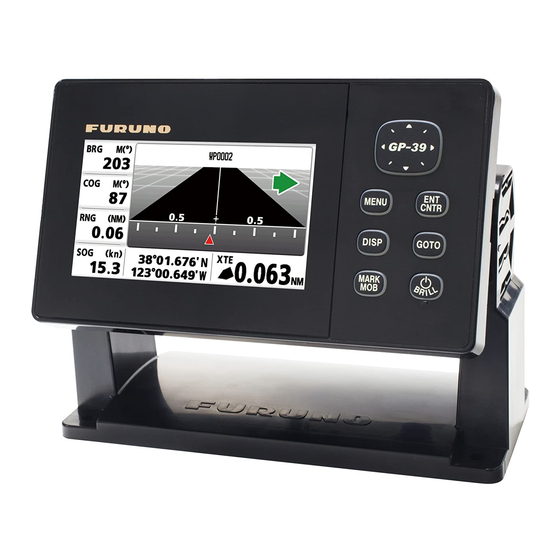
- Page 13 1. OPERATIONAL OVERVIEW Highway Display The highway display provides a 3D view of own ship’s progress toward destination. XTE (Cross-track error) scale and arrow mark Arrow shifts with boat’s XTE. When the arrow is aligned with the center line the boat is on course.
- Page 14 1. OPERATIONAL OVERVIEW Steering Display The steering display provides steering information. Speed over ground Bearing reference; Time MAG(netic) or TRUE Receiver status Bearing destination Bearing scale Own ship mark 14.6 Course over ground 0.46 Bearing to the destination 00 15 12/11/09 17:57:40 Time-To-Go...
- Page 15 1. OPERATIONAL OVERVIEW Satellite Monitor Display The satellite monitor display shows the condition of GPS and GEO (WAAS) satellites. Number, bearing and elevation angle of all GPS and GEO satellites (if applicable) in view of your receiver appear. Elevation Receiver status DOP value 1.60...
-
Page 16: Menu Overview
1. OPERATIONAL OVERVIEW Menu Overview Most operations of your unit are done through the menu. Below is a quick introduction on how to select a menu and change menu settings. If you get lost in operation, press the MENU key to return to the main menu. 1. - Page 17 1. OPERATIONAL OVERVIEW How to enter alphanumeric data Some menu operations require you to enter alphanumeric data (A to Z, 0 to 9) and symbols (&, _, #,’ , -, > and space). The procedure which follows shows how to enter alphanumeric data.
-
Page 18: How To Enter The Mob Mark
1. OPERATIONAL OVERVIEW How to Enter the MOB Mark The MOB mark denotes man overboard position. Only one MOB mark is displayed. Each time the MOB mark is entered the previous MOB mark and its position data are overwritten. 1. Press the MARK/MOB key until the following message appears. 2. -
Page 19: Plotter Display Overview
PLOTTER DISPLAY OVERVIEW How to Select the Display Range You can change the display range on the plotter and highway displays. The available horizontal range for the plotter display is: 0.02, 0.05, 0.1, 0.2, 0.5, 1, 2, 5, 10, 20, 40, 80, 160 and 320 nautical miles. -
Page 20: How To Shift The Display
2. PLOTTER DISPLAY OVERVIEW Cursor state and position indication Cursor position is displayed in latitude and longitude or TDs at the bottom of the plotter display when the cursor is shown. If there is no operation for about seven seconds, the cursor disappears. COG line Range from Own ship’s mark... -
Page 21: How To Change Track Plotting Interval, Stop Recording
2. PLOTTER DISPLAY OVERVIEW How to Change Track Plotting Interval, Stop Re- cording To trace the boat’s track, the boat’s position is stored into the memory at an interval of distance or according to display range. For distance, a shorter interval provides better reconstruction of the track, but the storage time of the track is shortened. -
Page 22: How To Change Track Color
2. PLOTTER DISPLAY OVERVIEW How to Change Track Color You can select the color for the tracks among red, yellow, green, blue, purple, black and brown. It is useful to change the color to distinguish tracks at different times of a day, for example. -
Page 23: How To Erase All Tracks
2. PLOTTER DISPLAY OVERVIEW 2.7.2 How to erase all tracks 1. Press the MENU key twice to show the main menu. 2. Select [Tracks], and press the ENT/CNTR key. 3. Select [Delete], and press the ENT/CNTR key. 4. Select [All], and press the ENT/CNTR key. 5. - Page 24 2. PLOTTER DISPLAY OVERVIEW This page is intentionally left blank.
-
Page 25: Waypoints
WAYPOINTS How to Enter Waypoints In navigation terminology a waypoint is a particular location on a voyage, whether it be a starting, intermediate or destination waypoint. Your unit can store 10,000 way- points. Waypoints can be entered on the plotter display: at cursor position, at own ship’s position, through the waypoints list and at the MOB position. - Page 26 3. WAYPOINTS 5. Confirm that [New] is selected, and press the ENT/CNTR key. The default name, Lat/Lon and Comment are as follows: Name: The youngest unused waypoint number. Lat, Lon: Current own ship position Comment: Current date/time 6. To change the waypoint name, press the ENT/CNTR key. Cursor 7.
-
Page 27: How To Enter Waypoints Automatically
3. WAYPOINTS 13. To change the comment, select [Comment] and press the ENT/CNTR key. 14. Enter the comment, and press the ENT/CNTR key. 15. Press the MENU key to register the new waypoint into the list. 16. To register other waypoints, repeat steps 4 through 14. 17. -
Page 28: How To Display Waypoint Name
3. WAYPOINTS How to Display Waypoint Name You can display waypoint names as follows: 1. Press the MENU key twice to show the main menu. 2. Select [Plotter Setup], and press the ENT/CNTR key. 3. Select [WP Name], and press the ENT/CNTR key. 4. -
Page 29: How To Edit Waypoints
3. WAYPOINTS How to Edit Waypoints Waypoint position, name, mark shape and comment can be edited on the plotter dis- play or through the waypoint list. Note: When the waypoint selected is set as the destination, the message "Change The Waypoint. Are you sure?" appears. 3.3.1 How to edit waypoints on the plotter display 1. -
Page 30: How To Move Waypoints
3. WAYPOINTS How to Move Waypoints You can move waypoints to any position on the plotter display. 1. Operate the cursorpad to place the cursor on the waypoint to move. 2. Press the ENT/CNTR key to show the pop-up window. 3. -
Page 31: How To Erase All Waypoints
3. WAYPOINTS 3.5.3 How to erase all waypoints 1. Press the MENU key twice to show the main menu. 2. Select [Delete], and press the ENT/CNTR key. 3. Confirm that [All Waypoints] is selected, and press the ENT/CNTR key. 4. Select [Delete], and press the ENT/CNTR key. When no waypoint is set as destination When a waypoint is set as destination 5. - Page 32 3. WAYPOINTS This page is intentionally left blank.
-
Page 33: Routes
ROUTES In many cases a trip from one place to another involves several course changes, re- quiring a series of waypoints which you navigate to, one after another. The sequence of waypoints leading to the ultimate destination is called a route. Your unit can auto- matically advance to the next waypoint on a route, so you do not have to change the destination waypoint repeatedly. - Page 34 4. ROUTES 5. Confirm that [New] is selected, and press the ENT/CNTR key to show the route information. 6. Press the ENT/CNTR key to change the route name. 7. Operate the cursorpad to enter the route name, and press the ENT/CNTR key (maximum: six characters).
-
Page 35: How To Edit Routes
4. ROUTES How to Edit Routes You can edit the route created. Note: When the route that is selected is set as route navigation, the message "Route is set as a destination. Are you sure?" appears. 4.2.1 How to replace a waypoint in a route 1. -
Page 36: How To Insert A Waypoint In A Route
4. ROUTES 4.2.3 How to insert a waypoint in a route To insert a waypoint in a route, do the following: 1. Press the MENU key twice to show the main menu. 2. Select [Routes], and press the ENT/CNTR key. 3. -
Page 37: How To Erase A Route
4. ROUTES 7. Select [Skip], and press the ENT/CNTR key to show “X” next to the waypoint se- lected at step 6. 8. Press the MENU key several times to close the menu. Note: To restore a waypoint to a route, select [Skip Off] at step 7, and press the ENT/ CNTR key. - Page 38 4. ROUTES This page is intentionally left blank.
-
Page 39: Destination
DESTINATION Destination can be set four ways: by cursor, by waypoint, by route and by MOB posi- tion. The previous destination is cancelled whenever a new destination is set. How to set a MOB position is described in section 1.6. When setting a destination, a blue line is shown between own ship and the destination selected. -
Page 40: How To Set Destination By Waypoint
5. DESTINATION How to Set Destination by Waypoint You can set a waypoint as a destination by using the cursor or the waypoints list. 5.2.1 How to set a destination waypoint with the cursor 1. On the plotter display, operate the cursorpad to place the cursor on the waypoint which you want to set as the destination. -
Page 41: How To Set Route As Destination
5. DESTINATION How to Set Route as Destination You can set a route as destination through the list. 1. Press the MENU key twice to show the main menu. 2. Select [Routes], and press the ENT/CNTR key. 3. Select [Alpha] or [Distance], and press the ENT/CNTR key. 4. -
Page 42: How To Cancel A Destination
5. DESTINATION How to Cancel a Destination You can cancel a destination by using the cursor, or through the list. 5.4.1 How to cancel a destination with the cursor 1. On the plotter display, operate the cursorpad to place the cursor on the waypoint (route) set as the current destination. -
Page 43: How To Set A Destination From Other Displays
5. DESTINATION 5. Select [Cancel Goto (Route)], and press the ENT/CNTR key. Cancel Route Navigation. Cancel Goto. Are you sure? Are you sure? (for route navigation) (for waypoint destination) 6. Select [Yes], and press the ENT/CNTR key. To cancel, select [No]. 7. - Page 44 5. DESTINATION This page is intentionally left blank.
-
Page 45: Alarms
ALARMS Overview There are eight alarm conditions which generate both audio and visual alarms: Arrival alarm, Anchor watch alarm, XTE (Cross-Track Error) alarm, Speed alarm, WAAS alarm, Time alarm, Trip alarm and Odometer alarm. When an alarm setting is violated, the buzzer sounds and the name of the offending alarm and the alarm icon appear on the display (alarms other than Speed Based Out- put). -
Page 46: Buzzer Type Selection
6. ALARMS Message and meanings Message Meaning XTE ALARM! The boat is off its intended course by the range set. TIME ALARM! The time set has come. SPEED ALARM! The boat’s speed is higher than the range set. ARRIVAL ALARM! The boat is approaching the arrival area. -
Page 47: How To Set An Alarm
6. ALARMS How to Set an Alarm Set alarms as below: Note: For the Anchor alarm, press the MARK/MOB key to enter the waypoint at own ship’s position, and set it as a destination referring to paragraph 5.2.1. 1. Press the MENU key twice to show the main menu. 2. -
Page 48: Alarm Descriptions
6. ALARMS Alarm Descriptions Arrival alarm The arrival alarm informs you that own ship is approaching a destination waypoint. The "arrival zone" is circle-shaped and the alarm setting is the radius of the circle. The alarm activates if your boat enters the circle. Alarm setting Destination waypoint Own ship’s... - Page 49 6. ALARMS WAAS alarm This alarm alerts you when the WAAS signal is lost (for all status indications except W2D/W3D). Note that [On] cannot be selected if [Mode] in [WAAS] menu is set to [GPS]. Time alarm The time alarm works like an alarm clock, releasing audio and visual alarms when the time entered has come.
- Page 50 6. ALARMS This page is intentionally left blank.
-
Page 51: Other Functions
OTHER FUNCTIONS This chapter describes menu items not covered in other chapters. Plotter Setup Menu COG Line You can show or hide the COG line on the plotter display. COG/BRG ref. Boat’s course and bearing to a waypoint are displayed in true or magnetic bearing. Magnetic bearing is true bearing plus (or minus) earth’s magnetic variation. -
Page 52: Delete Menu
7. OTHER FUNCTIONS - Manual (Speed calculated manually) 1. Press and ENT/CNTR in order. 2. Enter speed (1 to 999 knot), and press the ENT/CNTR key. Delete Menu You can delete all waypoints and routes listed in [Waypoint List] and [Route List]. GPS Setup Menu The GPS Setup menu smooths position and course, averages speed, applies position offset, and deactivates unhealthy satellites. - Page 53 (max. three satellites) in two digits. SV ELV (satellite elevation) Set the minimum elevation of satellites to use to fix position. Roll Over Set the year when the roll over occur. The GP-39 will automatically turns off and on to reset the satellite observation.
-
Page 54: Waas Menu
7. OTHER FUNCTIONS WAAS Menu *Use “0” (as default setting). Mode You can select [WAAS] or [GPS] for the position fixing mode. In both mode, [WAAS Search] has [Auto] or [Manual] as [WAAS Search] mode. When selecting [Auto], the mode automatically select the satellite. When selecting [Manual], you can manually select the satellite number. -
Page 55: System Menu
7. OTHER FUNCTIONS Display Select the position format. • xx.xxx’: Shows L/L position with no seconds. • xx’xx.x”: Displays L/L position with seconds. • LC TD: Loran C TDs Loran C When choosing LC TD at Display, do the following: 1) Press the ENT/CNTR key. - Page 56 7. OTHER FUNCTIONS Time Offset GPS uses UTC time. If you would rather use local time, enter the time difference (range: -14:00 to +14:00, 15 minutes step) between it and UTC time. Daylight Saving Time For countries that use daylight savings time, select On to enable daylight savings time. Time Display You can display the time in 12 or 24 hour format.
-
Page 57: User Display Menu
7. OTHER FUNCTIONS User Display Menu To customize user displays, which are [6] and [7] appeared when the DISP key is pressed (see section 1.4), use the User Display menu. DISP key is pressed Item name on User Display menu User display 1 Display [6] Display 1... - Page 58 7. OTHER FUNCTIONS 2. Select the screen division, which is the number of data to display, and press the ENT/CNTR key. The display now looks something like the one shown below, showing data choices and screen division selected. * : Depending on the selection at step 2. 3.
- Page 59 7. OTHER FUNCTIONS 2. Operate the cursorpad to select the column to select data, and press the ENT/ CNTR key. ODO: Odometer distance XTE: Cross-track error Trip: Trip distance TTG: Time to go Time: Time (to destination) Date: Date ETA: Estimated time to POSN: Position arrival (to destination) Volts: Power voltage...
-
Page 60: I/O Setup Menu
7. OTHER FUNCTIONS I/O Setup Menu Waypoint and route data can be uploaded or downloaded between a USB flash mem- ory and your unit. There are two kinds of data for route data: route data and route comment data. *: See chapter 9. Note: No position fix is available during uploading or downloading. - Page 61 7. OTHER FUNCTIONS Route data format $GPRTE, x.x, x.x, a, c--c, c--c, ... , c--c <CR><LF> 1: Number of sentences required for one complete route data (1 to 6) See note. 2: Number of sentences currently used (1 to 6) 3: Message mode (Always set to “C”.) 4: Route No.
-
Page 62: Uploading Data To A Usb Flash Memory
7.8.2 Downloading data from a USB flash memory Note 1: All waypoint and route data stored in the GP-39 will be deleted when data is downloaded from USB flash memory. Note 2: Do not remove the USB flash memory during data download. -
Page 63: Importing Data From Gp-32
7. OTHER FUNCTIONS 7.8.3 Importing data from GP-32 Waypoint and route data can be imported from GP-32 to GP-39 by connecting two GP units with serial cable. Preparation 1. Connect the serial cables of GP-32 and GP-39 as below illustration using the sig- nal converter. - Page 64 7. OTHER FUNCTIONS Operation on GP-32 Only after the operation on GP-39 is done, proceed to operate the GP-32. 1. Press the MENU key to show the main menu. 2. Select [I/O Setup], and press the ENT key. 3. Select [Save WPT/RTE -> PC?], and press the ENT key to select [CONTINUE?].
- Page 65 7. OTHER FUNCTIONS GP-39 shows below pop-up message. Loading completed. Push any key. 7-15...
- Page 66 7. OTHER FUNCTIONS This page is intentionally left blank. 7-16...
-
Page 67: Maintenance, Troubleshooting
MAINTENANCE, TROUBLE- SHOOTING NOTICE Do not apply paint, anti-corrosive sealant or contact spray to plastic parts or equipment coating. Those items contain products that can damage plastic parts and equipment coating. Maintenance Regular maintenance is important to maintain performance. Check the following points to help maintain performance. -
Page 68: Troubleshooting
8. MAINTENANCE, TROUBLESHOOTING Troubleshooting This section provides simple troubleshooting procedures which the user can follow to restore normal operation. If you cannot restore normal operation, do not attempt to check inside the unit. Any trouble should be referred to a qualified technician. Symptom Remedy You cannot turn on the... -
Page 69: Displaying The Message Board
8. MAINTENANCE, TROUBLESHOOTING Displaying the Message Board When an error occurs, a message and an alarm icon appear on the screen. The mes- sage board displays the error messages (see page 6-2) shown in table below. Messages and meanings Message Meaning, remedy GPS ERROR! Request service. -
Page 70: Clearing Data
8. MAINTENANCE, TROUBLESHOOTING Test Items Description Correct: “OK”, Wrong: “NG” GPS test Correct: “OK”, Wrong: “NG” Program version The program version No. which is currently used appears. Number of test repetition. 5. Press each key one by one. The corresponded mark on the display turns red if the key is functioning properly. 6. -
Page 71: Installation
INSTALLATION Equipment Lists Standard Supply Name Type Code No. Remarks Display unit GP-39 000-029-443 Antenna Unit GPA-017 000-029-316 w/10 m cable Spare Parts SP20-01601 001-435-700 Fuse FGMB 125V 1.5A PBF Self-tapping screw 5 16, 4 pcs. Installation CP20-03901 001-435-710... -
Page 72: Desktop Mount
9. INSTALLATION 9.2.2 Desktop mount 1. Detach the display unit from the hanger. Note: To detach the display unit from the hanger, align the arrow marks on the unit and hanger. If the arrows are not aligned when you detach the unit, you may damage the unit or the hanger. -
Page 73: Flush Mount
9. INSTALLATION 9.2.3 Flush mount Using Flush Mount Kit F (OP20-45) An optional flush mount kit type F is required. The table below shows the contents of the OP20-45 kit. Name: Flush Mount Kit F, Type: OP20-45, Code No. 001-435-860 Name Type Code No. - Page 74 9. INSTALLATION Using Flush Mount Kit S (OP20-46) An optional flush mount kit type S is required. The table below shows the contents of the OP20-46 kit. Name: Flush Mount Kit F, Type: OP20-46, Code No. 001-435-780 Name Type Code No 4 ...
-
Page 75: Installation Of Antenna Unit
9. INSTALLATION Installation of Antenna Unit Install the antenna unit referring to the antenna installation diagram at the back of this manual. When choosing a mounting location for the antenna unit, keep in mind the fol- lowing points: • Select a location out of the radar beam. The radar beam will obstruct or prevent re- ception of the GPS signal. -
Page 76: Input/Output Data
9. INSTALLATION Input/Output Data This equipment inputs/outputs NMEA0183 data shown below. Note that NMEA0183 version (1.5/2.0/3.0) can be a selected from the I/O setup screen. NMEA0183 Input Sentence Talker Format Note PFEC, GPwp1 PFEC, GPrtc PFEC, GPxfr PFEC, cprst Request for Target PFEC, SDmrk Mark Additional information of longitude, latitude and its position. - Page 77 9. INSTALLATION Output setting 1. Press the MENU key twice to show the main menu. 2. Select [I/O Setup], then press the ENT/CNTR key. 3. Select [Data 1] or [NMEA0183 Version] depending on the equipment connected. 4. Press the ENT/CNTR key. One of the following screens appears depending on the item selected at step 3.
- Page 78 9. INSTALLATION This page is intentionally left blank.
-
Page 79: Appendix 1 Menu Tree
APPENDIX 1 MENU TREE MENU Bold Italic: Default setting Zoom (only when the plotter/highway display is shown Plotter: 0.5kn, Highway: 2kn) (press) Ship To Center (only when the plotter display is shown) Tracks Rec (Off, Distance, Auto; 0.00 to 9.99, 0.10 nm) Color (Red, Yellow, Green, Blue, Purple, Black, Brown) Delete (All, By Color) Track Memory Used (**%) - Page 80 APPENDIX 1 MENU TREE Display (xx.xxx', xx'xx.x", LC TD) Pos/TD Setup Loran C (4990: Central Pacific, 11-29) TD1 (-99.9 to +99.9; +0.0) TD2 (-99.9 to +99.9; +0.0) System Key Beep (Off, On) Language (English, others) Units (NM, kn / km, km/h / sm, mph) Time Offset (-14:00 to +14:00;...
-
Page 81: Appendix 2 What Is Sbas
APPENDIX 2 WHAT IS SBAS? A satellite based augmentation system, or SBAS (Satellite Based Augmentation System), is an augmentation system that uses additional messages from satellite broadcasts to support regional and wide area augmentation. SBAS provides GPS signal corrections to SBAS users, for even bet- ter position accuracy, through the GPS error corrections that are widely broadcasted from the geo- stationary satellite. -
Page 82: Appendix 3 List Of Terms
APPENDIX 3 LIST OF TERMS The following table shows the terms used in GP-39. Terms/Symbols Meaning Terms/Symbols Meaning Waypoints Latitude Longitude Own Ship Loran-C Man Overboard M, Mag Magnetic “M” Shortest course to the March destination Cursor Percentage MM (MMM) -
Page 83: Appendix 4 Geodetic Chart List
APPENDIX 4 GEODETIC CHART LIST : Alaska 001: WGS84 090: NORTH AMERICAN 1927 002: WGS72 091: NORTH AMERICAN 1927 : Bahamas (excl. San Salvador Is.) Mean Value (Japan, Korea & Okinawa) 003: TOKYO 092: NORTH AMERICAN 1927 : Bahamas, San Salvador Is. : Mean Value (CONUS) 004: NORTH AMERICAN 1927 093: NORTH AMERICAN 1927 (Cont’d) : Canada (incl. - Page 84 APPENDIX 4 GEODETIC CHART LIST This page is intentionally left blank. AP-6...
-
Page 85: Specifications
FURUNO GP-39 SPECIFICATIONS OF GPS RECEIVER GP-39 ANTENNA UNIT Receiving channel 12 channels parallel, 12 satellites tracking SBAS 2 channels Rx frequency 1575.42 MHz ±1.023 MHz Rx code GPS: C/A code, SBAS: L1 C/A Position fixing system All in view, 8 state Kalman filter Position accuracy 10 m (95% of the time, HDOP ≦... - Page 86 FURUNO GP-39 POWER SUPPLY Display unit 12-24 VDC: 0.7-0.3 A ENVIRONMENTAL CONDITIONS Ambient temperature Antenna unit -25°C to +70°C (storage: -30°C to +75°C) Display unit -15°C to +55°C (storage: -30°C to +75°C) Relative humidity 93% or less at +40°C Degree of protection...
-
Page 87: Packing Lists
PACKING LIST 20BH-X-9851 -3 GP-39 N A M E DESCRIPTION/CODE № O U T L I N E Q'TY ユニット UNIT 空中線部 GPA-017 ANTENNA UNIT 000-029-316-00 受信演算部 GP-39 DISPLAY UNIT 000-029-445-00 予備品 SPARE PARTS 予備品 SP20-01601 SPARE PARTS 001-435-820-00 付属品 ACCESSORIES... - Page 92 esumi...
-
Page 95: Index
INDEX Alarm icon ..........6-1 Insert a waypoint in a route ....... 4-4 Alarm message ......... 6-1 alphanumeric data........1-9 Key Beep........... 7-5 Anchor watch alarm ........6-4 Arrival alarm ..........6-4 Lat Offset........... 7-3 LCD brilliance..........1-3 buzzer ............6-2 Life of LCD .......... - Page 96 INDEX Trip alarm ...........6-5 TTG/ETA SPD ...........7-1 Units ............7-5 Uploading data to a PC ......7-12 User Display..........1-7 WAAS alarm ..........6-5 WAAS Search ..........7-4 Waypoint data format .......7-10 Waypoint Name .........3-4 XTE (Cross Track Error) alarm ....6-4 IN-2...