Table of Contents
Advertisement
Quick Links
Advertisement
Table of Contents
Troubleshooting

Related Manuals for Furuno GP-33


Summary of Contents for Furuno GP-33
- Page 1 GPS Navigator GP-33 www.furuno.co.jp...
- Page 2 Nishinomiya, 662-8580, JAPAN Telephone : +81-(0)798-65-2111 : +81-(0)798-65-4200 Printed in Japan All rights reserved. Pub. No. OME-44580-C1 (YOTA ) GP-33 The paper used in this manual is elemental chlorine free. ・FURUNO Authorized Distributor/Dealer A : JAN C1 : JAN . 31, 2011...
-
Page 3: Important Notice
How to discard a used battery Some FURUNO products have a battery(ies). To see if your product has a battery(ies), see the chapter on Maintenance. Follow the instructions below if a battery(ies) is used. Tape the + and - terminals of battery before dispossal to prevent fire, heat generation caused by short circuit. -
Page 4: Safety Instructions
Failure to turn off the equipment can cause fire or electrical shock. Contact a FURUNO agent for service. CAUTION The glass of an LCD panel breaks easily. Handle the LCD carefully. Injury can result if the glass breaks. -
Page 5: Table Of Contents
TABLE OF CONTENTS FOREWORD... v SYSTEM CONFIGURATION ... vi OPERATIONAL OVERVIEW ...1-1 1.1 Controls ...1-1 1.2 How to Turn Power On/Off ...1-2 1.3 How to Adjust LCD and Key Panel Brilliance ...1-3 1.4 Display Modes ...1-3 1.5 Menu Overview...1-8 1.6 How to Enter the MOB Mark...1-9 PLOTTER DISPLAY OVERVIEW...2-1 2.1 How to Select the Display Range ...2-1 2.2 How to Shift the Cursor ...2-1... - Page 6 TABLE OF CONTENTS 5.2.2 How to set a destination waypoint through the list ... 5-2 5.3 How to Set Route as Destination ... 5-2 5.4 How to Cancel Destination... 5-3 5.4.1 How to cancel destination with the cursor... 5-3 5.4.2 How to cancel destination through the list...
-
Page 7: Foreword
A Word to the Owner of the GP-33 Congratulations on your choice of the GP-33 GPS Navigator. For over 60 years FURUNO Electric Company has enjoyed an enviable reputation for innovative and dependable marine electronics is furthered by our extensive global network of agents and dealers. -
Page 8: System Configuration
SYSTEM CONFIGURATION Standalone system Antenna Unit GPA-017 Receiver Unit GP-33 CAN bus network When optional junction box FI-5002 is connected Antenna Unit GPA-017 Receiver Unit GP-33 Navigation MOB Switch External Alarm 12-24VDC Standard configuration is shown with solid line. Navigation... - Page 9 When no FI-5002 is connected Receiver Unit GP-33 Category of Units Units Antenna Unit GPA-017 Receiver Unit GP-33 Junction Box FI-5002 (Option) Antenna Unit GPA-017 Backbone cable Category Exposed to weather Protected from weather SYSTEM CONFIGURATION Navigation MOB Switch External Alarm...
- Page 10 SYSTEM CONFIGURATION This page is intentionally left blank. viii...
-
Page 11: Operational Overview
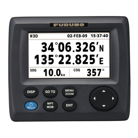
OPERATIONAL OVERVIEW Controls DISP GO TO MENU ZOOM (Cursorpad) Description Selects display mode. Sets destination. -Opens the Menu. (plotter and highway displays: twice, others: once) -Shows the zoom window (plotter and highway displays only). -Shifts the cursor. -Selects item on menus. -Long press: Turns power off. -
Page 12: How To Turn Power On/Off
1. OPERATIONAL OVERVIEW How to detach the hard cover from the unit Put your thumbs on the front and forefingers on the catches at the sides of the cover, and pull it toward you. Catches How to Turn Power On/Off 1. -
Page 13: How To Adjust Lcd And Key Panel Brilliance
How to Adjust LCD and Key Panel Brilliance 1. Press the /BRILL key to show the following window. 2. To adjust the LCD brilliance, press The setting changes “0→1→…→7→6…0→1…” continuously. Maximum setting is 7. You can use also the cursorpad ( , 3. - Page 14 1. OPERATIONAL OVERVIEW Plotter Display The plotter display traces own boat’s track. Receiver status Horizontal display range scale Range to cursor* Bearing to cursor* *:COG and SOG replace bearing to cursor and range to cursor when the cursor is not displayed. Waypoint mark (Shape selectable) Course bar...
- Page 15 Highway Display The highway display provides a 3-D view of own boat’s progress toward destination. XTE (Cross-track error) scale and arrow mark Arrow shifts with boat’s XTE. When the arrow is aligned with the center line the boat is on course.
- Page 16 1. OPERATIONAL OVERVIEW Steering Display The steering display provides steering information. Speed over ground Bearing reference; MAG(netic) or TRUE Receiver status 14.6 0.46 00 15 Time-To-Go to destination Range from own boat to destination Nav Data Display Receiver status 34 44.589 135 21.074 14.6 Speed over ground...
- Page 17 Satellite Monitor Display The satellite monitor display shows the condition of GPS and GEO (WAAS) satellites. Number, bearing and elevation angle of all GPS and GEO satellites (if applicable) in view of your receiver appear. Elevation Receiver status GEO satellite 22 08 32 30 12.0...
-
Page 18: Menu Overview
1. OPERATIONAL OVERVIEW Menu Overview Most operations of your unit are done through the menu. Below is a quick introduction to how to select a menu and change menu settings. If you get lost in operation, press the MENU/ZOOM key to return to the main menu. 1. -
Page 19: How To Enter The Mob Mark
How to enter alphanumeric data Some menu operations require you to enter alphanumeric data (A to Z, 0 to 9) and symbols (&, _, #,’ , -, > and space). The procedure which follows shows how to enter alphanumeric data. For example, to change the waypoint name “WP0006” to “KOBE”, do the follows: 1) Press 2) Press... - Page 20 1. OPERATIONAL OVERVIEW Shortest course from own boat to MOB position (blue) 0.20 Bearing from own boat to MOB position Range from own boat to MOB position 1-10 MOB mark (red) E 135 09.750 E 135 10.000 N 34 08.500 N 34 08.375...
-
Page 21: Plotter Display Overview
PLOTTER DISPLAY OVERVIEW How to Select the Display Range You can change the display range on the plotter and highway displays. The horizontal range in the plotter display is available among 0.02, 0.05, 0.1, 0.2, 0.5, 1, 2, 5, 10, 20, 40, 80, 160 and 320 nautical miles. -
Page 22: How To Shift The Display
2. PLOTTER DISPLAY OVERVIEW Cursor state and position indication Cursor position is displayed in latitude and longitude or TDs at the bottom of the plotter display when the cursor is shown. If there is no operation for about seven seconds, the cursor disappears. Range from own boat to cursor Bearing from... -
Page 23: How To Change Track Plotting Interval, Stop Recording
How to Change Track Plotting Interval, Stop Re- cording To trace the boat’s track, the boat’s position is stored into the memory at an interval of distance or according to display range. For distance, a shorter interval provides better reconstruction of the track, but the storage time of the track is shorten. When the track memory becomes full, the oldest track is erased to make room for the latest. -
Page 24: How To Change Track Color
2. PLOTTER DISPLAY OVERVIEW How to Change Track Color You can select the color for the tracks among red, yellow, green, blue, purple, black and brown. It is useful to change the color to distinguish tracks at different times of a day, for example. -
Page 25: How To Erase All Tracks
Note: To cancel, select [No] at this step. 7. Press the MENU/ZOOM key twice to close the menu. 2.6.2 How to erase all tracks 1. Press the MENU/ZOOM key twice to show the main menu. 2. Select [Tracks], and press the ENT key. 3. - Page 26 2. PLOTTER DISPLAY OVERVIEW This page is intentionally left blank.
-
Page 27: Waypoints
WAYPOINTS How to Enter Waypoints In navigation terminology a waypoint is a particular location on a voyage, whether it be a starting, intermediate or destination waypoint. Your unit can store 10,000 way- points. Waypoints can be entered on the plotter display: at cursor position, at own boat’s position, through the waypoints list and at the MOB position. - Page 28 3. WAYPOINTS 4. Confirm that [New] is chosen, and press the ENT key. The default name, Lat/Lon and Comment are as follows: Name: The youngest unused waypoint number. Lat, Lon: Current own boat position Comment: Current date/time 5. To change the waypoint name, press the ENT key. 6.
-
Page 29: How To Enter Waypoints Automatically
12. To change the comment, select [Comment] and press the ENT key. 13. Enter the comment, and press the ENT key. 14. Press the MENU/ZOOM key to register the new waypoint into the list. 15. To register other waypoints, repeat steps 4 through 14. 16. -
Page 30: How To Display Waypoint Name
3. WAYPOINTS How to Display Waypoint Name You can display waypoint names as follows: 1. Press the MENU/ZOOM key twice to show the main menu. 2. Select [Plotter Setup], and press the ENT key. 3. Select [WP Name], and press the ENT key. 4. -
Page 31: How To Edit Waypoints
How to Edit Waypoints Waypoint position, name, mark shape and comment can be edited on the plotter dis- play or through the waypoint list. Note: When the waypoint chosen is set as the destination, the message "Change The Waypoint. Are you sure?" appears. 3.3.1 How to edit waypoints on the plotter display 1. -
Page 32: How To Move Waypoints
3. WAYPOINTS How to Move Waypoints You can move waypoints to any position on the plotter display. 1. Operate the cursorpad to place the cursor on the waypoint to move. 2. Press the ENT key to show the pop-up window. 3. -
Page 33: How To Erase Waypoints
How to Erase Waypoints You can erase each or all waypoint(s). Note: You cannot erase the waypoint used as the current destination. (See para- graphs paragraph 3.5.1, paragraph 3.5.2.) 3.5.1 How to erase a waypoint on the plotter display 1. Operate the cursorpad to place the cursor on the waypoint to erase. 2. -
Page 34: How To Erase All Waypoints
3. WAYPOINTS 3.5.3 How to erase all waypoints 1. Press the MENU/ZOOM key twice to show the main menu. 2. Select [Delete], and press the ENT key. 3. Confirm that [All Waypoints] is chosen, and press the ENT key. 4. Select [Delete], and press the ENT key. When no waypoint is set as destination When a waypoint is set as destination 5. -
Page 35: Routes
ROUTES In many cases a trip from one place to another involves several course changes, re- quiring a series of waypoints which you navigate to, one after another. The sequence of waypoints leading to the ultimate destination is called a route. Your unit can auto- matically advance to the next waypoint on a route, so you do not have to change the destination waypoint repeatedly. - Page 36 4. ROUTES 4. Confirm that [New] is chosen, and press the ENT key to show the route informa- tion. 5. Press the ENT key to change the route name. 6. Operate the cursorpad to enter the route name, and press the ENT key (maxi- mum: six characters).
-
Page 37: How To Edit Routes
How to Edit Routes You can edit the route created. Note: When the route chosen is set as route navigation, the message "Route is set as a destination. Are you sure?" appears. 4.2.1 How to replace a waypoint in a route 1. -
Page 38: How To Insert A Waypoint In A Route
4. ROUTES 4.2.3 How to insert a waypoint in a route To insert a waypoint in a route, do the following: 1. Press the MENU/ZOOM key twice to show the main menu. 2. Select [Routes], and press the ENT key. 3. -
Page 39: How To Erase A Route
8. Press the MENU/ZOOM key several times to close the menu. Note: To restore waypoint to a route, select [Skip Off] at step 7, and press the ENT key. How to Erase a Route You can erase routes individually or collectively. 4.3.1 How to erase a route through the route list Note: The route used as route navigation can not be erased. - Page 40 4. ROUTES This page is intentionally left blank.
-
Page 41: Destination
DESTINATION Destination can be set four ways: by cursor, by waypoint, by route and by MOB posi- tion. Previous destination is cancelled whenever a new destination is set. The setting by MOB position is described in chapter 1. When setting a destination, a blue line is shown between own boat and the destination selected. -
Page 42: How To Set Destination By Waypoint
5. DESTINATION How to Set Destination by Waypoint You can set a waypoint as destination by using the cursor or the waypoints list. 5.2.1 How to set a destination waypoint with the cursor 1. On the plotter display, operate the cursorpad to place the cursor on the waypoint which you want to set as the destination. -
Page 43: How To Cancel Destination
3. Select [Alpha] or [Local], and press the ENT key. RT000 : WP000 ->WP0001 RT001 : WP003 ->WP0001 RT002 : WP001 ->WP0005 RT003 : WP001 ->WP0004 4. Select the route to set as a destination, and press the ENT key. 5. -
Page 44: How To Cancel Destination Through The List
5. DESTINATION 2. Press the ENT key. WP0001 Move Cancel Goto Edit Delete (for waypoint destination) (for QP destination) 3. Select [Cancel Goto (Route)], and press the ENT key. Cancel Goto. Are you sure? (for waypoint destination) 4. Chose [Yes], and press the ENT key. To cancel, select [No]. -
Page 45: Alarms
ALARMS Overview There are nine alarm conditions which generate both audio and visual alarms: Arrival alarm, Anchor watch alarm, XTE (Cross-Track Error) alarm, Speed alarm, Speed Based Output alarm, WAAS alarm, Time alarm, Trip alarm and Odometer alarm. When an alarm setting is violated, the buzzer sounds and the name of the offending alarm and the alarm icon appear on the display (alarms other than Speed Based Out- put). -
Page 46: Buzzer Type Selection
6. ALARMS Message and meanings Message XTE ALARM! TIME ALARM! SPEED ALARM! ARRIVAL ALARM! TRIP ALARM! ODOMETER ALARM! ANCHOR WATCH! NO WAAS SIGNAL! Note: The message screen also shows equipment trouble. See section 8.3. Buzzer Type Selection The buzzer sounds whenever an alarm setting is violated. You can select the type of buzzer as follows: 1. - Page 47 2. Select [Alarms], and press the ENT key. 3. Select an alarm item, and press the ENT key. 4. Do one of the following: (Arrival/Anchor) 1) Select [Arrival] or [Anchor], and press the ENT key. 2) Press and ENT key. 3) Enter the alarm area, and press the ENT key.
-
Page 48: Alarm Descriptions
6. ALARMS Alarm Descriptions Arrival alarm The arrival alarm informs you that own boat is approaching a destination waypoint. The area that defines an arrival zone is that of a circle which you approach from the outside of the circle. The alarm will activate if your boat enters the circle. Own boat’s position Anchor watch alarm... - Page 49 XTE (Cross-Track Error) alarm The XTE alarm warns you when own boat is off its intended course. Own boat’s position Speed alarm The speed alarm alerts you when the boat’s speed is higher than the alarm range set. WAAS alarm This alarm alerts you when the WAAS signal is lost.
- Page 50 6. ALARMS This page is intentionally left blank.
-
Page 51: Other Functions
OTHER FUNCTIONS This chapter describes menu items not carried in other chapters. Plotter Setup Menu COG Line You can show or hide the COG line on the plotter display. COG/BRG ref. Boat’s course and bearing to a waypoint are displayed in true or magnetic bearing. Magnetic bearing is true bearing plus (or minus) earth’s magnetic variation. -
Page 52: Gps Setup Menu
7. OTHER FUNCTIONS TTG/ETA SPD To calculate time to go and estimated time of arrival, enter your speed as below. -Auto (GPS calculated speed) 1. Press and ENT in order. 2. Enter the speed average (1 to 999 sec.) to use, and press the ENT key. -Manual (Speed calculated manually) 1. - Page 53 Every GPS satellite is broadcasting abnormal satellite number(s) in its Almanac, which contains general orbital data about all GPS satellites. Using this information, the GPS receiver automatically eliminates any malfunctioning satellite from the GPS sat- ellite schedule. However, the Almanac sometimes may not contain this information.
-
Page 54: Waas Menu
7. OTHER FUNCTIONS WAAS Menu Mode You can select GPS or WAAS for the position fixing mode. WAAS Search For WAAS setting, the GEO satellite is searched automatically or manually. For GEO satellite number, see page AP-3. Auto: The system automatically searches for the optimum GEO satellite from your current position. -
Page 55: System Menu
7. OTHER FUNCTIONS Display Select the position format. • xx.xxx’: Shows L/L position with no seconds. • xx’xx.x”: Displays L/L position with seconds. • LC TD: Loran C TDs Loran C When choosing LC TD at Display, do the following: 1) Press the ENT key. - Page 56 7. OTHER FUNCTIONS Time Offset GPS uses UTC time. If you would rather use local time, enter the time difference (range: -14:00 to +14:00, 15 minutes step) between it and UTC time. Daylight Saving Time For countries that use daylight savings time, select On to enable daylight savings time. Time Display You can display the time in 12 or 24 hour format.
-
Page 57: User Display Menu
User Display Menu To customize user displays, which are [6] and [7] appeared when the DISP key is pressed (see section 1.4), use the User Display menu. User display 1 User display 2 Note: You can show the User Display menu by pressing the ENT key more than three seconds at the User display 1 (display [6]) and 2 ([7]). - Page 58 7. OTHER FUNCTIONS Display 1, Display 2 You can select items to show on the User display 1 (display [6]) and 2 ([7]), from among digital data, speedometer and COG (see page 1-7). When choosing [Off] for Display 2, for example, the display [7] is not shown. For [Digital], you can display one to four items of digital navigation data on the user display.
- Page 59 4. Select data desired, and press the ENT key. 5. Repeat steps 3 and 4 to set other data. You can select digital data also from the User display 1 (display [6]) and 2 ([7]) directly. 1. Press the DISP key several times to show User display 1 or 2 desired, and press the ENT key to show the cursor.
-
Page 60: I/O Setup Menu
7. OTHER FUNCTIONS I/O Setup Menu Waypoint and route data can be uploaded from your unit to a PC, or downloaded from a PC to your unit. There are two kinds of data for route data: route data and route comment data. Note: No position fix is available during uploading or downloading. - Page 61 Waypoint data format $PFEC, GPwpl, llll.ll, a, yyyyy.yy, a, c—c, c, c—c, a, hhmmss, xx, xx, xxxx <CR><LF> 1: Waypoint latitude 2: N/S 3: Waypoint longitude 4: E/W 5: Waypoint name (1 to 8 characters) 6: Waypoint color (NULL/0: black, 1: red, 2: yellow, 3: green, 4: brown, 5: purple, 6: blue) 7: Waypoint comment (”@_ (see below.)”...
- Page 62 7. OTHER FUNCTIONS Route data format $GPRTE, x.x, x.x, a, c--c, c--c, ... , c--c <CR><LF> 1: Number of sentences required for one complete route data (1 to 6) See note. 2: Number of sentences currently used (1 to 6) 3: Message mode (Always set to “C”.) 4: Route No.
-
Page 63: Uploading Data To A Pc
7.7.2 Downloading data from PC Note that all waypoint and route data stored in the GP-33 will be deleted when data is downloaded from PC. 1. Connect a PC to your GP-33, referring to the interconnection diagram at the back of this manual. - Page 64 7. OTHER FUNCTIONS This page is intentionally left blank. 7-14...
-
Page 65: Maintenance, Troubleshooting
MAINTENANCE, TROUBLE- SHOOTING Maintenance Regular maintenance is important to maintain performance. Check the following points to help maintain performance. • Check that connectors on the rear panel are firmly tightened and free of rust. • Check that the ground system is free of rust and the ground wire is tightly fastened. •... -
Page 66: Troubleshooting
8. MAINTENANCE, TROUBLESHOOTING Troubleshooting This section provides simple troubleshooting procedures which the user can follow to restore normal operation. If you cannot restore normal operation, do not attempt to check inside the unit. Any trouble should be referred to a qualified technician. Symptom You cannot turn on the power. -
Page 67: Displaying The Message Board
Displaying the Message Board When an error occurs, a message and an alarm icon appear on the screen. The mes- sage board displays the error messages (see page 6-2) shown in table below. Messages and meanings Message GPS ERROR! GPS NO FIX! RAM ERROR! ROM ERROR! BACKUP ERROR! -
Page 68: Clearing Data
8. MAINTENANCE, TROUBLESHOOTING Test Items ROM, RAM test Data3 test GPS test Program version No. 5. Press each key one by one. The corresponded mark on the display turns red if the key is functioning properly. 6. Press the MENU/ZOOM key three times to close the test screen. 7. -
Page 69: Installation
• Locate the unit away from exhaust pipes and vents. • The mounting location should be well ventilated. • Mount the unit where shock and vibration are minimal. Standard Supply Type Code No. GP-33 GPA-017 CP20-03300 1 set FP20-01200 1 set... -
Page 70: Desktop And Underside Of Table Mount
9. INSTALLATION • Locate the unit away from equipment which generates electromagnetic fields such as a motor or generator. • Allow sufficient maintenance space at the sides and rear of the unit and leave suf- ficient slack in cables, to facilitate maintenance and servicing. •... -
Page 71: Flush Mount
9.2.3 Flush mount 1. Using the template (supplied), cut out a hole in the mounting location. 2. Prepare four pilot holes (for 3x20 self-tapping screws) at the mounting location. 3. Unscrew knobs to dismount the receiver unit from the hanger. This hanger can be discarded. -
Page 72: Installation Of Antenna Unit
• Select a location out of the radar beam. The radar beam will obstruct or prevent re- ception of the GPS signal. • The location should be well away from a VHF/UHF antenna. A GPS receiver is in- terfered by a harmonic wave of a VHF/UHF antenna. -
Page 73: Wiring
M12-05BM+05BF-060 cable to connect to the 12-24 VDC switch board. (For other cores, cut them and tape individually.) Ground to switchboard (12-24VDC) Antenna Unit GPA-017 Receiver Unit GP-33 w/10 m cable FRU-10BFFM-02M cable (for NMEA 0183) Navigator, PC, External Alarm, etc. M12-05BM+05BF-060 cable, 6 m (Red: +, Black: -) - Page 74 9. INSTALLATION Connection with the optional junction box FI-5002 Detailed information for the service technician about CAN bus wiring is in the docu- ment titled “Furuno CAN bus Network Design Guide (TIE-00170-*)” separately. Power cable (2m) Black White 12VDC to switchboard...
- Page 75 Terminator • When connecting to backbone cable GP-33 Terminator Backbone cable Attach the following terminators to both ends of the backbone cable. Name Terminator (male) LTWMN-05AMMT-SL8001 Terminator (female) LTWMN-05AFFT-SL8001 Terminator (male) LTWMC-05BMMT-SL8001 Terminator (female) LTWMC-05BFFT-SL8001 When connecting to the optional junction box FI-5002 There are two terminal resistors (R1 and R2) inside the FI-5002.
-
Page 76: Language Setting
9. INSTALLATION Language Setting When you first turn the power on after installation, you are asked the language to use on the equipment. Press Input/Output Data This equipment inputs/outputs NMEA0183 or CAN bus data shown below. Note that NMEA 0183 version (2.0 or 3.0) can be a selected from the I/O setup screen. Data 1: CAN bus port (input) 059904 060928... - Page 77 Data 1: CAN bus port (output) 059392 ISO Acknowledgement 060928 ISO Address Claim 061184 Self Test Group Function 126208 NMEA-Acknowledge group function 126464 PGN List Transmit and Received PGNs Group Function 126720-1 Memory Clear Group Function 126720-2 Reset Group Function 126992 System Time 126996...
- Page 78 9. INSTALLATION Data 2/Data 3: NMEA Output Sentence Format** AAM* APB* BOD* BWC* BWR* RMB* For PC only. (See Chapter 7.) REM1/REM2: Radar, echo sounder, etc. AP: Autopilot *: Not output when no waypoint is set. **: Talker; GP 9-10 REM1 REM2...
- Page 79 Output setting 1. Press the MENU/ZOOM key twice to show the main menu. 2. Select [I/O Setup], then press the ENT key. 3. Select [Data 2], [Data 3] or [NMEA0183 Version] depending on the equipment connected. 4. Press the ENT key. One of the following screens appears depending on the item selected at step 3.
- Page 80 9. INSTALLATION This page is intentionally left blank. 9-12...
-
Page 81: Appendix 1 Menu Tree
APPENDIX 1 MENU TREE MENU Ship To Center (only when the plotter display is shown) ZOOM Tracks Waypoints Routes Plotter Setup Alarms Messages (Alarm and error messages are shown when occurred.) Delete Rec (Off, Distance, Auto; 0.00 to 9.99, 0.1 nm) Color (Red, Yellow, Green, Blue, Purple, Black, Brown) Delete (All, By Color) Track Memory Used (**%) - Page 82 APPENDIX 1 MENU TREE GPS Setup Datum (WGS84, WGS72, Other; 003 to 173) Navigation (Rhumb Line, Great Circle) Smooth Position (0 to 999 s, 0 s) Smooth S/C (0 to 9999 s, 5 s) Lat Offset (0.000 N/S to 9.999 N/S, 0.000’ N) Lon Offset (0.000 E/W to 9.999 E/W, 0.000’E) Disable SV SV ELV (5 to 90 , 5 )
-
Page 83: Appendix 2 What Is Waas
APPENDIX 2 WHAT IS WAAS? WAAS, available in North America, is a provider in the worldwide SBAS (Satellite Based Augmen- tation System) navigation system. CBAS provides GPS signal corrections to SBAS users, for even better position accuracy, typically better than three meters. There are three more SBAS providers, MSAS (Multi-Functional Satellite Augmentation System) for Japan, EGNOS (Euro Geostationary Navigation Overlay Service) for Europe and GAGAN (GPS And GEO Augmented Navigation) for India. -
Page 84: Appendix 3 List Of Terms
APPENDIX 3 LIST OF TERMS The following table shows the terms used in GP-33. Terms/Symbols Meaning Waypoints Own Boat Man Overboard “M” Shortest course to the destination Cursor Percentage 2D GPS position fix 3D GPS position fix 2D WAAS position fix... -
Page 85: Appendix 4 Geodetic Chart List
APPENDIX 4 GEODETIC CHART LIST 001: WGS84 002: WGS72 Mean Value (Japan, Korea & Okinawa) 003: TOKYO : Mean Value (CONUS) 004: NORTH AMERICAN 1927 : Mean Value 005: EUROPEAN 1950 : Australia & Tasmania 006: AUSTRALIAN GEODETIC 1984 : Mean Value (Ethiopia & Sudan) 007: ADINDAN : Ethiopia 008: ADINDAN... - Page 86 APPENDIX 4 GEODETIC CHART LIST This page is intentionally left blank. AP-6...
-
Page 87: Specifications
059904, 060928, 061184, 065286, 126208/720 Output data 059392, 060928, 061184, 126208/464/720/992/996, 127258, 129026/029/033/044/283/284/285/538/539/540, 130822/823 Contact signal Event switch (MOB input), Speed alarm (output) GP-33 0.02/0.05/0.1/0.2/0.5/1/2/5/10/20/40/80/160/320 NM 2 channel All in view, 8-state Kalman filter 3 m (95% of the time, 2drms) 999.9 kn... - Page 88 12-24 VDC: 0.24-0.12 A (Non CAN bus) ENVIRONMENTAL CONDITION Ambient temperature Antenna unit Receiver unit -15°C to +55°C Relative humidity 93% at 40°C Degree of protection IP56 Vibration IEC 60945 UNIT COLOR Antenna unit N9.5 Receiver unit N2.5 -25°C to +70°C SP - 2 GP-33 E4458S01B-M...
- Page 92 Mar.27'07 R.Esumi...
-
Page 95: Index
INDEX Alarm icon ... 6-1 Alarm message ... 6-1 alphanumeric data... 1-9 Anchor watch alarm ... 6-4 Arrival alarm ... 6-4 buzzer ... 6-2 Buzzer type ... 6-2 CAN bus... 9-5 Centering own boat’s position ... 2-2 COG Line ... 7-1 COG/BRG ref. - Page 96 INDEX Time Offset ...7-6 Track Color ...2-4 Track Memory Used...2-3 Trip alarm ...6-5 TTG/ETA SPD ...7-2 Units ...7-5 Uploading data to a PC ...7-13 User Display...1-7 WAAS alarm ...6-5 WAAS Search ...7-4 Waypoint data format ...7-11 Waypoint Name ...3-4 WPT/MOB key ...1-1 XTE (Cross Track Error) alarm ...6-5 IN-2...