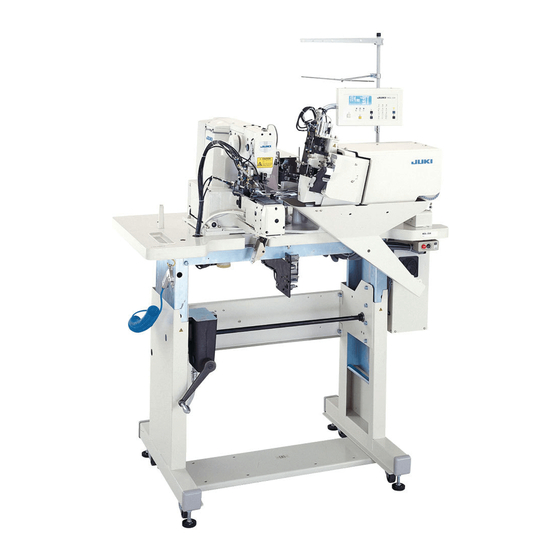
JUKI MOL-254 Engineer's Manual
2-needle, automatic belt-loop attaching machine
Hide thumbs
Also See for MOL-254:
- Manual (179 pages) ,
- Instruction manual (110 pages) ,
- Handbook (272 pages)

Related Manuals for JUKI MOL-254


Summary of Contents for JUKI MOL-254
- Page 1 2-needle, Automatic Belt-loop Attaching Machine MOL-254 ENGINEER’S MANUAL 29341005 No.00...
- Page 2 Instruction Book intended for the maintenance personnel and sewing operators at a sewing factory. All personnel engaged in repair of MOL-254 are required to carefully read Section 2 “Standard Adjustment” which contains important information on the maintenance of MOL-254.
-
Page 3: Table Of Contents
CONTENTS 1. SPECIFICATIONS ..................1 2. NAMES AND FUNCTIONS OF COMPONENTS ........3 [1] Names and functions of the main unit..............3 [2] Names and functions of operation box panel ............4 3. TIMING CHART ..................6 4. STANDARD ADJUSTMENT ..............7 [1] Machine head components.................. - Page 4 (9) Disassembling/assembling of components ................. 55 1) Disassembling/assembling of the timing belt ................55 2) Disassembling/assembling of the throat plate ................. 69 3) Disassembling/assembling of the hook removing cross roller ..........71 4) Disassembling/assembling of the ball spline ................73 [2] Device components ....................
- Page 5 5. OPERATION BOX PANEL ..............153 [1] Operating procedure of the maintenance screen ..........153 (1) [CA] Setting of starting angle of the 1st hook thread trimming cylinder drive ......153 (2) [CB] Setting of ending angle of the 1st hook thread trimming cylinder drive ......153 (3) [CC] Setting of starting angle of the 2nd hook thread trimming solenoid drive ......
- Page 6 (9) F5 fuse (6.3AT) ......................... 179 (10) F6 fuse (6.3AT) ........................179 [2] Replacing the parts .................... 180 (1) Replacing EPROM ........................180 (2) Replacing the fuse ........................181 [3] Change of the power specifications ..............182 (1) [General export] ......................... 182 1) Setting of the power voltage specifications ................
- Page 7 * The description covered in this engineer’s manual is subject to change for improvement of the TELEX : J22967 commodity without notice. Copyright (C) 1999 JUKI CORPORATION. All rights reserved throughout the world. 99 · 11 Printed in Japan (E)
-
Page 8: Specifications
1. SPECIFICATIONS 1) Max. sewing speed : 2,500 rpm (sewing pitch : 3.4 mm or less) 2) Hook : Horizontal semi-rotary hook (oil wick lubrication) 3) Bobbin : 1.8 fold hook 4) Thread take-up : Link thread take-up 5) Needle : DPx17 #19 to #21 For domestic : DPx17 #19 For export... - Page 9 29) Loop cut method : Selection of cross cut and straight cut (Range : 9 mm to 20 mm) (Cross cut at the time of delivery) 30) Loop cut : Cutting method by engaging moving knife with counter knife 31) Loop bending : Fork folding method Loop supply drive method : Front and rear assisted drive method (stepping...
-
Page 10: Names And Functions Of Components
2. NAMES AND FUNCTIONS OF COMPONENTS [1] Names and functions of the main unit Temporary stop switch The switch is used to temporarily stop Operation box panel <P29> the machine operation. The panel is used to specify/display/ actuate functions. Sewing machine head Thread stand The machine head The stand is used to... -
Page 11: Names And Functions Of Operation Box Panel
[2] Names and functions of operation box panel Name of switch Function Set ready switch This switch is used to perform origin retrieval of the sewing machine and loop supplying device. The machine is set to the sewing stand-by state. Display screen moves to sewing screen. - Page 12 a. This key is used to enter the setting screen. Standard screen key b. When changing the sewing data, keep pressing this key for 10 seconds to release data-lock, In addition, data is locked when keeping pressing this key again. Ten key These keys are used when inputting various nemeric data.
-
Page 13: Timing Chart
3. TIMING CHART This diagram gives a basic timing chart. It has to be noted that the operation may vary if an alarm occurs or input from any of switches and sensors is made. (Caution) For the basic operation flow, refer to page 25 of the Instruction Manual. Standard operating timing chart Start SW Machine rotation Machine stop... -
Page 14: Standard Adjustment
4. STANDARD ADJUSTMENT [1] Machine head components Standard Adjustment (1) Adjustment of the main shaft components 1) Removing the play of main shaft Thrust collar Machine arm Main shaft Main shaft bushing, middle Thread trimmer cam 2) Installing the main shaft coupling Main shaft rear bearing Servo motor Rubber ring... - Page 15 Adjustment Procedures Results of Improper Adjustment ○ Pulling the thread trimmer cam in the direction of the arrow mark, lightly press the thrust collar to the main shaft bushing, middle to fit the thrust collar. ① Provide a clearance of 0.5 mm between the servo motor ○...
-
Page 16: Adjusting The Main Shaft Sensor
Standard Adjustment 3) Adjusting the main shaft sensor Coupling Sensor Sensor installing base Sensor Slit plate Pass the center. 4) Stretching the timing belt (Main shaft-to-hook driving shaft for the front side timing) Main shaft Idler pulley − −... - Page 17 Adjustment Procedures Results of Improper Adjustment ○ Adjust so that the slit plate passes almost the center of the sensor and there is no interference, then tighten setscrew 1) Bring the needle bar to the lowest position of its stroke. Timing with the hook on the rear 2) Loosen the idler pulley and loosen the timing belt.
-
Page 18: Adjusting The Idler
Standard Adjustment 5) Adjusting the idler 1 kgf 4 mm (2) Adjusting the hook driving shaft components 1) Adjusting the longitudinal position of the oscillator Hook driving shaft gear Thrust collar Face A Oscillator − −... - Page 19 Adjustment Procedures Results of Improper Adjustment ① Loosen setscrews and adjust the idler. If the timing belt is excessiuely ② Using the belt tension as the standard, adjust the tension pressed, main shaft torque is so that the belt sags 4 mm when the center of the belt is increased.
-
Page 20: Adjusting The Backlash Of The Oscillator Gear
Standard Adjustment 2) Adjusting the backlash of the oscillator gear Thrust collar (large) Face A Thrust collar (small) 0.1 mm or less 3) Removing the play of the hook driving shaft − −... - Page 21 Adjustment Procedures Results of Improper Adjustment ① Loosen setscrew ○ If the backlash is too large, hook ② Perform the adjustment of the backlash by turning thrust noise will be increased. ○ If the backlash is too small, collar (large) in the direction of the arrow mark while making the collar (large) closely come in contact with face A on seizure of the oscillator or main the machine bed.
-
Page 22: Adjusting The Thread Trimmer Mechanism Components
Standard Adjustment (3) Adjusting the thread trimmer mechanism components Adjusting the position of the thread trimmer cam Position in the main shaft direction : adjust clearance provided between the thread trimmer cam and the main shaft thrust collar to 0.5 mm. Position in the direction of rotation : Align the engraved marker dot on the main shaft with the engraved marker line on the thread trimmer cam. - Page 23 Adjustment Procedures Results of Improper Adjustment ○ Determine the position of the thread trimmer cam and ○ Failure of thread trimming will tighten screw No. 1 of the thread trimmer cam from the occur. ○ Machine-lock will occur at the upper face of the sewing machine.
-
Page 24: Adjusting The Thread Trimming Cylinder (Front Side)
Standard Adjustment Adjusting the thread trimming cylinder (front side) ○ The clearance of is 1 mm at the stroke end of the pulling side of the thread trimming cylinder when the thread trimming cam is as shown in Fig. 1 (concave of the thread trimmer cam comes below). - Page 25 Adjustment Procedures Results of Improper Adjustment Loosen nuts to adjust the thread trimming cylinder. If the clearance is smaller than 1 mm, moving knife locating in the sewing position will excessively protrude from the throat plate. This causes the moving knife to interfere with the moving knife on the opposite side when making the distance between this side seam...
-
Page 26: Position Of The Thread Trimmer Shaft
Standard Adjustment 4) Position of the thread trimmer shaft Make sure that the rear end of thread trimmer shaft is aligned with worked plane on the machine arm in the state that thread release pin in thread release arm comes off thread release notch (thread trimmer stopper support comes in contact with stopper section on the machine arm). - Page 27 Adjustment Procedures Results of Improper Adjustment ① Loosen setscrew ○ If thread trimmer shaft in the cam follower. (Shaft is possible to rotate.) Loosen two setscrews in the thread release mistakenly adjusted, receiving arm thrust collar. amount of front section ②...
-
Page 28: Position Of The Thread Trimming Solenoid
Standard Adjustment 6) Position of the thread trimming solenoid ① Turn the main shaft to the supporting run section of the thread trimmer cam [refer to Adjusting the thread trimmer link stopper screw], move the thread trimming solenoid in the direction of the arrow mark , and the cam follower moves in the direction of ②... - Page 29 Adjustment Procedures Results of Improper Adjustment ○ Thread trimming roller enters the Loosen adjustment screw in the thread trimming solenoid and adjust the position of thread trimming solenoid arm so groove in thread trimmer cam that a clearance of 1 mm is provided between the cam face and failure of thread trimming or of thread trimmer cam and the roller attaching face of cam machine-lock will occur.
-
Page 30: Adjusting Moving And Counter Knives
Standard Adjustment 7) Adjusting moving and counter knives ★ Position of the moving knife Adjust the position so that the t o p e n d o f m o v i n g k n i f e protrudes 1.2 mm from the front Counter knife end of throat plate. - Page 31 Adjustment Procedures Results of Improper Adjustment ○ If the clearance is smaller than 1) Position of the counter knife Loosen counter knife setscrews and adjust the position. 0.8 mm, blade tip of the counter knife cuts thread when the (Caution) For the normal operation, the moving knife moving knife pulls thread.
-
Page 32: Height Of The Moving And Counter Knives
Standard Adjustment 8) Height of the moving and counter knives Perform a trial cut of two pieces each of #80 and #5 threads with the moving and counter knives (by operating the thread trimming lever by hand after having removed the throat plate to check that the respective pairs of threads are properly cut). - Page 33 Adjustment Procedures Results of Improper Adjustment Adjust the height of the moving knife according to the thickness of washer. If proper adjustment of the moving knife cannot be obtained, select and use one of the following parts. Part No. Name of part Thickness B242328000A Washer...
-
Page 34: Adjusting The Thread Trimmer Cam Timing (Only For This Side)
Standard Adjustment 10) Adjusting the thread trimmer cam timing (only for this side) Adjust the timing of the moving knife on this side and that on far side so that the moving knife on this side is located at its travel end when the moving knife on far side starts returning from its travel end. As observed from A Thread trimmer cam B Fig. - Page 35 Adjustment Procedures Results of Improper Adjustment ○ If the timing between the moving 1) Expel air from the machine. 2) Remove the side cover from the hook base. knife on this side and that on far 3) Loosen two setscrews in the thread trimmer cam B and side differs from the standard adjust the timing of the thread trimmer cam.
-
Page 36: Position Of The Tension Release Stopper
Standard Adjustment 2) Position of the tension release stopper Adjust the clearance provided between end face of the cam follower and tension relesase arm pin to 1.0 mm in the state that the thread trimming operation is not performed. Cam follower Thread trimmer shaft Thread release arm Thread trimmer... - Page 37 Adjustment Procedures Results of Improper Adjustment ① Remove tension release return spring ○ If the clearance is excessively ② Loosen two setscrews and press the tension release large, when adjusting the stopper in the direction of the arrow mark ( ⇨ ) while releasing amount to a rather making the tension release stopper closely come in cantact extensive value, the disk is not...
-
Page 38: Adjusting The Sensor Components
Standard Adjustment (5) Adjusting the sensor components 1) Adjusting the Y origin sensor Needle Presser Fig. 1 Y sensor slit Y sensor 2) Adjusting the X origin sensor X origin sensor Needle X sensor slit Presser Fig. 1 − −... - Page 39 Adjustment Procedures Results of Improper Adjustment ① Set the set value of <CB> on the operation box panel to “0.0” to perform the origin retrieval. ② At this time, loosen sensor slit setscrew and adjust the sensor in the direction of the arrow mark so that the center inside the presser is aligned with the needle tip as shown in Fig.
-
Page 40: Adjusting The Feed Mechanism Components
Standard Adjustment (6) Adjusting the feed mechanism components 1) Adjusting the position of the X/Y motors X motor Y motor − −... - Page 41 Adjustment Procedures Results of Improper Adjustment 1. Lightly press the Y motor in the direction of the arrow mark If the pressing is insufficient, and tighten three setscrews again. defective needle entry will 2. Loosen four setscrews , lightly press the X motor in the occur, and if the pressing is direction of the arrow mark (⇨), and tighten setscrews excessive, X-Y moving torque...
-
Page 42: Adjusting The Position Of The Cloth Presser Foot
Standard Adjustment 2) Adjusting the position of the cloth presser foot Adjust so that clearances A provided between the needle and the cloth presser foot should be equal in front and in the rear. Center 40 to 70 mm (1.574” to 2.755”) −... - Page 43 Adjustment Procedures Results of Improper Adjustment Far side : The position has been factory-adjusted at the time of delivery since it is used as reference when assembling the relevant components. If it should be out of the correct position, re- adjustment has to be carried out taking the following procedure.
-
Page 44: Adjusting The Position Of The Cloth Presser Lower Plate
Standard Adjustment 3) Adjusting the position of the cloth presser lower plate Adjust so that the cloth presser foot and the cloth presser lower plate are aligned with each other in terms of the longitudinal and lateral positions. At this time, the clearance provided between needles is 57.1 mm. ☆... - Page 45 Adjustment Procedures Results of Improper Adjustment Loosen setscrews to adjust the position. If the lower plate protrudes from the cloth presser foot, it will interfere with needle and needle breakage or thread breakage may occur. If the presser foot is excessively Loosen lock nut in the presser bar lifting cylinder and turn raised, skew may be produced.
-
Page 46: Adjusting The Position Of The Needle Bar And The Hook
Standard Adjustment (7) Adjusting the position of the needle bar and the hook 1) Adjusting the height of the needle bar Adjust so that the upper engraved marker line on the needle bar on this side is aligned with the lower end face of the needle bar lower bushing at the lowest dead point of the needle bar. - Page 47 Adjustment Procedures Results of Improper Adjustment 1) Remove the face plate. If the engraved marker line on the 2) Loosen two setscrews in the needle bar connection and needle bar is higher than the end move the needle bar up or down to adjust the height. face of the lower bushing, stitch 3) After performing the adjustment, securely tighten two skipping may occur often, and if it...
-
Page 48: Adjusting Needle-To-Inner Hook Timing (Same Adjustment For This Side And Far Side)
Standard Adjustment 3) Adjusting needle-to-inner hook timing (Same adjustment for this side and far side) 1) Needle bar timing When the needle bar goes up from its lowest dead point, the lower engraved marker line on the needle bar is aligned with the end face of the needle bar lower bushing. (Fig. 1) 2) Hook timing The center of the needle is aligned with the blade point of inner hook (section ) at the time of step... - Page 49 Adjustment Procedures Results of Improper Adjustment 1) Align the lower engraved marker line with the end face of 1) For floppy materials, slightly the bushing referring to the height of the needle bar ① of retard the hook timing. On the the standard adjustment.
-
Page 50: Adjusting The Position Of The Shuttle Upper Spring (Same Adjustment For This Side And Far Side)
Standard Adjustment 4) Adjusting the position of the shuttle upper spring (Same adjustment for this side and far side) The lateral position in terms of the needle entry point should be equal on both left and right sides. Adjust the longitudinal position so that the rear end of the needle is aligned with corner section (Caution) If there is a scratch on section , bobbin thread breakage will occur. - Page 51 Adjustment Procedures Results of Improper Adjustment ○ If the position is shifted in any Remove the cloth feed base, the cloth presser lower plate, and the throat plate, and adjust the position with screw direction, front/rear or left/right, a phenomenon that needle (Caution) ○...
-
Page 52: Adjusting The Timing Of The Hook On This Side
Standard Adjustment 6) Adjusting the timing of the hook on this side The timing of the hook on this side and that of the hook on far side should be adjusted so that the respective hooks invert simultaneously at the time of catching the thread. −... - Page 53 Adjustment Procedures Results of Improper Adjustment 1) Remove the cover from the hook base. If the hook timing is not correct, the 2) Loosen three setscrews in the removing shaft crank needle will not enter the recess on and adjust the hook timing. the shuttle body when it comes down, causing the needle to (Caution) The timing has been factory-adjusted at the...
-
Page 54: Adjusting Procedure Of The Hook Removing Sensor
Standard Adjustment 7) Adjusting procedure of the hook removing sensor Notch − −... - Page 55 Adjustment Procedures Results of Improper Adjustment 1. Set the operation box panel to the adjustment screen and select [BB], hook adjustment mode. 2. Move the hook with the ten key so that the center-to-center of the needle holes on this side and far side is 69 mm as shown in Fig.
-
Page 56: Adjusting The Play In The Hook Removing Ball Screw
Standard Adjustment 8) Adjusting the play in the hook removing ball screw When there is a play in the hook base (front side) in the moving direction, make sure that there is any play in the thrust bearings of the ball screw. −... - Page 57 Adjustment Procedures Results of Improper Adjustment Screw ball screw lock nuts (double nut) so that thrust bearings smoothly turn without any play. − −...
-
Page 58: With Regard To Sewing
Standard Adjustment (8) With regard to sewing 1) Adjusting the thread take-up spring Stroke : Stroke of the thread take-up spring on this side may be different from that of the thread take- up spring on far side. Tension : Adjust the thread take-up spring tension in accordance with the thread tension. Fig. - Page 59 Adjustment Procedures Results of Improper Adjustment Adjusting the stroke If the stroke is too large, slip-off of 1) Turn OFF the power to the machine while the sewing the thread is likely to occur. machine is being actually engaged in sewing. If the stroke fails to match the thread 2) Turn the handwheel by hand until the needle thread is tension, the thread will excessively...
-
Page 60: Adjusting The Position Of The Wiper
Standard Adjustment 2) Adjusting the position of the wiper The wiper should be placed in a position where it spreads thread. (Refer to Fig. 1.) Needle Thread Moving direction in thread path Fig. 1 Fig. 2 − −... - Page 61 Adjustment Procedures Results of Improper Adjustment 1) Turn OFF the power to the machine and expel air from the machine while the sewing machine is being actually engaged in sewing. (Bring the needle to its stop position by turning the handwheel by hand.) 2) Pull out the wiper by hand and make sure of the relation of position with the thread.
-
Page 62: Disassembling/Assembling Of Components
Standard Structure (9) Disassembling/assembling of components 1) Disassembling/assembling of the timing belt ’ − −... - Page 63 Disassembling / Assembling 1. Remove head cover A and head cover B 2. Loosen setscrew and remove idler pulley base 3. Remove top cover 4. Loosen setscrew and remove main shaft slit plate 5. Loosen setscrew and remove main shaft sensor 6.
- Page 64 Standard Structure Disassembling of the timing belt − −...
- Page 65 Disassembling / Assembling 7. Loosen setscrew and remove cam follower stopper 8. Loosen counter weight setscrews 9. Loosen setscrew in hand pulley gear 10. Loosen setscrew in intermediate bushing thrust collar 11. Loosen setscrew in thread trimmer cam 12. Loosen setscrew in crank rod and remove 13.
- Page 66 Standard Structure Disassembling of the timing belt − −...
- Page 67 Disassembling / Assembling 19.Loosen setscrews in ball spline connecting collar At this time, loosen two setscrews only on ball spline side 20.Remove setscrews in ball spline and remove the ball spline in the direction of the arrow mark. At this time, take care not to allow the spline shaft to slip from the ball nut. 21.Loosen setscrew in oscillating eccentric shaft 22.Loosen setscrews...
- Page 68 Standard Structure Assembling of the timing belt Counter weight Pulley gear Thrust collar Belt Intermediate bushing Front bushing Main shaft Thread trimmer cam Fig. 2 Fig. 3 − −...
- Page 69 Disassembling / Assembling 1. Fit timing belt inside the machine head. (Caution) The timing belt prevents water absorption by means of the drying agent, silicagel. Perform the tension adjustment within two hours after taking out the belt from the packing case. 2.
- Page 70 Standard Structure − −...
- Page 71 Disassembling / Assembling 10.Fit the oscillating eccentric shaft. Refer to pages 11, 12, 13, and 14 for the relation of position and the adjustment. (Caution) At this time, adjust so that the oscillating eccentric cam enters between the timing belt. Oscillating eccentric shaft Belt 11.Insert ball spline...
- Page 72 Standard Structure 1 kgf 4 mm − −...
- Page 73 Disassembling / Assembling 13. Install idler pulley base and adjust the belt tension. For reference of the belt tension, adjust so that the belt sags 4 mm when the center of the belt is pressed with a 1 kgf load. (Caution) After adjusting the belt tension, be sure to turn the hand pulley and make sure that the belt does not interfere with other components.
- Page 74 Standard Structure To be in parallel − −...
- Page 75 Disassembling / Assembling 15.Install main shaft motor . Refer to page 7 for the installation. 16.Install main shaft sensor slit and main shaft sensor . Refer to page 9 for the installation. 17.Install hook removing unit . Temporarily tighten unit fixing screws and temporarily tighten the unit to hook connecting plate with fixing screw...
-
Page 76: Disassembling/Assembling Of The Throat Plate
Disassembling / Assembling Procedure 2) Disassembling/assembling of the throat plate 1) Loosen setscrew in the cloth feed plate guide, remove setscrews to remove the cloth presser lower plate. 2) Remove setscrews to remove the throat plates. * Perform the assembling by reversing the above disassembling order. −... - Page 77 Cautions to be taken when disassembling Cautions to be taken when assembling ○ When installing the throat plate (far side), fit the (Caution) When removing the throat plate, be sure to perform the hole in the moving knife link over the pin of the initial confirmation of the thread trimming lever.
-
Page 78: Disassembling/Assembling Of The Hook Removing Cross Roller
Disassembling / Assembling Procedure 3) Disassembling/assembling of the hook removing cross roller To come in close contact with each other Fig. 1 To come in close contact with each other Right side Left side Fig. 2 − −... - Page 79 Disassembling / Assembling Disassembling 1. Remove setscrews fixing hook connecting plate 2. Loosen three pressing screws in cross roller and remove six cross roller screws to remove the first hook. 3. Remove six hexagonal bolts in the cross roller to remove the cross roller. Assembling 1.
-
Page 80: Disassembling/Assembling Of The Ball Spline
Standard Adjustment 4) Disassembling/assembling of the ball spline 0.05 − −... - Page 81 Disassembling / Assembling Disassembling 1. Remove setscrews in ball spline 2. Loosen setscrews in connecting collar and remove the ball spline in the direction of the arrow mark. 3. Remove setscrews fixing follower sprocket and belt guide 4. Remove setscrews fixing sprocket base Assembling 1.
-
Page 82: Device Components
[2] Device components Standard Adjustment (1) Loop cut components 1) Adjusting the height of the loop cut knife unit ○ The top surfaces of the counter knife and the loop clamp base plate should be aligned with each other when the loop clamp base plate is approached to the loop cut counter knife. Top surfaces should be aligned with each other. - Page 83 Adjustment Procedures Results of Improper Adjustment ○ If the height of the top surface of 1. Remove the cover from the feed gear. 2. Loosen two setscrews in the knife device bracket and the loop clamp base plate is move knife device bracket up or down to adjust the different from that of the loop cut height of the top surfaces.
-
Page 84: Adjusting The Cross Cut Angle Of The Loop Cut Knife
Standard Adjustment 2) Adjusting the cross cut angle of the loop cut knife 1. The assembling dimension of the knife turn rod end connected to the knife turn cylinder should be 142.7±1 mm. 142.7 ± 1 mm 2. Adjust so that processed plane A of the loop feeding base should be almost in parallel with processed plane B of the counter knife base in the state that the knife turn cylinder is fully drawn. - Page 85 Adjustment Procedures Results of Improper Adjustment ○ If the position of the knife turn 1. Loosen the lock nut in knife turn rod end , turn the rod of knife turn cylinder , and adjust the assembling dimension rod end is not proper, the cross to the specified standard one.
-
Page 86: Adjusting The Position Of The Loop Cut Center
Standard Adjustment 3) Adjusting the position of the loop cut center 1. For the cross cut type, adjust the loop cut position to the center of the loop. Loop center − −... - Page 87 Adjustment Procedures Results of Improper Adjustment ○ If the cross cut center is not in 1. Loosen fixing screw in the knife base bracket and move the regular position, dog ear will adjustment screw of the loop cut center in the direction result.
-
Page 88: Changing The Straight Cutting
Standard Adjustment 4) Changing the straight cutting 1. Adjust so that the loop cut knife is at straight angle against the belt loop. * State of the cross cut * State of the straight cut 90˚ − −... - Page 89 Adjustment Procedures Results of Improper Adjustment ○ A f t e r t h e c o m p l e t i o n o f 1. Remove the chip cover. 2. Draw out the rod in knife turn cylinder and turn counter adjustment, perform a trial of knife base...
- Page 90 Standard Adjustment SW 6 − −...
- Page 91 Adjustment Procedures Results of Improper Adjustment 5. Remove the cover located on the right side of operation box panel and turn ON SW 6 of the lower side of the DIP switches which are located both on upper and lower sides. Approximate value 6.
- Page 92 Standard Adjustment − −...
- Page 93 Adjustment Procedures Results of Improper Adjustment ○ For the moving amount of the 7. Turn ON the power and supply air to the machine. 8. Pressing the standard screen key, press ten key “0” to set knife unit guide rail and “BC” the screen to the adjustment screen.
-
Page 94: Adjusting The Loop Cut Cylinder Sensor
Standard Adjustment 5) Adjusting the loop cut cylinder sensor 1. The lamp of sensor should light up when the cylinder is in the lowest position of its stroke. At this time, make sure that the lamp lights up at the highest position of sensor −... - Page 95 Adjustment Procedures Results of Improper Adjustment ○ A d j u s t m e n t o f t h e s e n s o r 1. Turn ON the power and supply air to the machine. 2. Pressing the standard screen key, press ten key “0” to position will affect the cycle time.
-
Page 96: Adjusting The Installation Of The Belt Loop Splice Sensor
Standard Adjustment 6) Adjusting the installation of the belt loop splice sensor 1. Backlash between the shaft gear of the difference in height portion and the sensor gear of the difference in height portion is 0.03 to 0.2 mm. ○ Data input screen −... - Page 97 Adjustment Procedures Results of Improper Adjustment 1. Install potentiometer on sensor plate of difference in height portion 2. Temporarily fix sensor gear of difference in height portion to potentiometer At this time, fix the sensor gear so that fixing screw the sensor gear of difference in height portion faces to the upper side.
- Page 98 Standard Adjustment 7. Level meter on the panel is displayed on scale 3 to 5 in the state that there is no belt loop. [Difference in height portion input screen] Level meter − −...
- Page 99 Adjustment Procedures Results of Improper Adjustment 6. Loosen fixing screw in the sensor gear of difference in height portion, insert the slotted screwdriver into the shaft hole in sensor gear of difference in height portion , and turn the shaft of potentiometer ○...
-
Page 100: Loop Clamp Feed Components
Standard Adjustment (2) Loop clamp feed components 1) Adjusting the loop clamp base plate front sensor 1. Operate the machine by the step operation and adjust the clearance provided between the loop clamp base plate and the cross cut receiving portion to 1 to 2 mm when the loop clamp base plate travels to its front end. - Page 101 Adjustment Procedures Results of Improper Adjustment ○ If the position of the adjustment 1. Loop clamp base plate may interfere with cross cut of loop clamp base plate front receiver . First, move sensor to far side. sensor is improper, the loop 2.
-
Page 102: Adjusting The Loop Clamp Base Plate Rear Sensor
Standard Adjustment 2) Adjusting the loop clamp base plate rear sensor 1. The loop clamp guide plate sensor should overlap approxamately 1 mm with the sensor slit at the position where the loop clamp base plate travels to its rear end. Sensor slit Sensor installing plate Sensor... - Page 103 Adjustment Procedures Results of Improper Adjustment ○ If the position of the sensor 1. Move loop clamp base plate by hand to travel it to its rear end. located on the rear side of the 2. At this position, adjust the sensor installing plate to the l o o p c l a m p b a s e p l a t e i s position where the sensor overlaps approximately 1 mm improper, step-out of the sensor...
-
Page 104: Adjusting The Loop Clamp Lever Loop Existence Sensor
Standard Adjustment 3) Adjusting the loop clamp lever loop existence sensor 1. Press No. 6 button of the solenoid valve on the device side and adjust the loop clamp detector plate to the position where the display of state changes over from OFF to ON and further the display of state continues to be OFF when a piece of board of 1 mm in thickness is inserted. - Page 105 Adjustment Procedures Results of Improper Adjustment ○ If the installing position of the 1. Turn ON the power and supply air to the machine. 2. Pressing the standard screen key, press ten key “0” to sensor slit is improper, the enter the adjustment screen.
-
Page 106: Adjusting The Opening Amount Of The Loop Clamp Base
Standard Adjustment 4) Adjusting the opening amount of the loop clamp base 1. Length of engagement of the knuckle joint is 4 to 4.5 mm. Opening width of the loop clamp lever is 7 mm 4 to 4.5 mm 5) Adjusting the position of the loop clamp feed unit 1. - Page 107 Adjustment Procedures Results of Improper Adjustment 1. Adjust the length of engagement of knuckle joint If the opening of the loop clamp attached to loop clamp lever and the rod of open/close lever is excessively wide, it may cylinder to 4 to 4.5 mm. interfere with the belt loop click.
-
Page 108: Belt Loop Feed Components
Standard Adjustment (3) Belt loop feed components 1) Adjusting the height (clearance) of the loop feed roller 1. Clearance provided between the loop feed roller and the roller placed under the loop feed roler is 0.3 to 0.5 mm. (Caution) It is recommended to change the adjustment value according to the belt loops. 0.3 to 0.5 −... - Page 109 Adjustment Procedures Results of Improper Adjustment ○ If the clearance is smaller as 1. Remove the chip cover. 2. Turn height adjusting screw of the loop feed roller placed against the belt loop, the belt under loop feed base and adjust the clearance provided loop may be damaged by the between loop feed roller and roller...
-
Page 110: Adjusting The Pressure Of The Loop Feed Roller
Standard Adjustment 2) Adjusting the pressure of the loop feed roller 1. Lift the rotary shaft of the feed roller and adjust the pressure to 34.3 to 44.1N. (Caution) It is recommended to change the adjustment value according to the belt loops. 34.3 to 44.1N −... - Page 111 Adjustment Procedures Results of Improper Adjustment ○ If the pressure is higher as 1. Remove the chip cover. against the belt loop, the belt 2. Turn pressure adjustment screw of the loop feed roller loop may be damaged by the placed under loop feed base and adjust the pressure of feed teeth of the belt loop feed...
-
Page 112: Adjusting The Tension Of The Loop Feed Roller Belt
Standard Adjustment 3) Adjusting the tension of the loop feed roller belt 1. Adjust the belt tension so that the belt sags approximately 0.6 mm when the center of the belt is pressed with 2.94N force. 2.94 N Loosening side Stretching side −... - Page 113 Adjustment Procedures Results of Improper Adjustment ○ I f t h e b e l t i s e x c e s s i v e l y 1. Loosen fixing screws in feed motor bracket , and stretch the belt while turning the bracket and motor stretched, the service life of belt clockwise making the position of the upper screw on this will be deteriorated or driving...
-
Page 114: Belt Loop Supply Components
Standard Adjustment (4) Belt loop supply components 1) Adjusting the tension of the loop supply belt 1. Adjust the belt tension so that the belt sags approximately 4.6 mm when the center of the belt is pressed with 3.92 N. Deflection of 4.6 mm 3.92 N −... - Page 115 Adjustment Procedures Results of Improper Adjustment ○ I f t h e b e l t i s e x c e s s i v e l y 1. Loosen the fixing screws in the motor installing base and stretch the belt with belt tension adjustment screw stretched, the service life of belt 2.
-
Page 116: Adjusting The Play In The Rotation Of The Loop Supply Slide Base
Standard Adjustment 2) Adjusting the play in the rotation of the loop supply slide base Adjust so that the play in the loop supply slide base in terms of the rotating direction should be 0.1 mm or less at the shoulder portion of the loop supply slide base. 0.1 mm or less 0.1 mm or less −... - Page 117 Adjustment Procedures Results of Improper Adjustment ○ If the clearance is improper, 1. Loosen fixing screws in the loop supply slide base guide defective delivery from the belt and move loop slide base guide up or down to adjust receiver to the fork or that from so that the clearance at the shoulder portion of loop supply the fork to the machine will slide base...
-
Page 118: Adjusting The Loop Supply Slide Base Sensor
Standard Adjustment 3) Adjusting the loop supply slide base sensor 1. Adjust the position of the sensor to the position where the bottoms of the fork end of the forks are aligned with the right end faces of the belt loops when the forks clamp the belt loops at the belt receiver portion. - Page 119 Adjustment Procedures Results of Improper Adjustment ○ The position of the loop supply 1. Turn ON SW 2 of the DIP switches which are located on the upper and lower sides on the right side of the operation slide base sensor has to be re- box panel to set the stop operation mode.
-
Page 120: Adjusting The Height Of The Fork (Up/Down Of This Side And Far Side)
Standard Adjustment 4) Adjusting the height of the fork (up/down of this side and far side) 1. Clearances provided between the top surface sides of the forks in the right and left rotation centers and the bottom surfaces of the belt loops should be equal respectively at the positions where the forks clamp the belt loops from the loop receivers. - Page 121 Adjustment Procedures Results of Improper Adjustment ○ Dog ear will result. 2. Align the heights of forks in the right and left rotation ○ Delivery on the one side of forks centers with screws for adjusting the height of folding shaft assembled in folding shaft metals only will be unstable.
-
Page 122: Adjusting The Height Of The Fork (Up/Down Of The Unit)
Standard Adjustment 5) Adjusting the height of the fork (up/down of the unit) 1. A clearance of 0.2 to 0.5 mm should be securely provided between the top surface side of the fork in rotation center and the bottom surface of the belt loop at the position where the fork clamps the belt loop from the loop receiver. - Page 123 Adjustment Procedures Results of Improper Adjustment ○ Dog ear will result. 1. Loosen the lock nut of rod end assembled in the rod of ○ Delivery of belt loop will be up/down cylinder of loop supply cam unstable. 2. Change the length of engagement between the cylinder rod and the rod end to adjust so that a clearance of 0.2 to 0.5 mm provided between the top surface side of the fork in rotation center and the bottom surface of the belt loop...
-
Page 124: Adjusting The Position Of The Fork And The Needle
Standard Adjustment 6) Adjusting the position of the fork and the needle 1. Parallelism of the fork ends of the respective forks as against the two sewing machine needles should be within 0.1 mm. 2. The space between the center of the sewing machine needle and the center of the fork in the rotation center is “0”... - Page 125 Adjustment Procedures Results of Improper Adjustment ○ Slippage of the position of upper 1. Loosen screws in the folding shaft metal bracket and move the folding shaft metal bracket to the right or left to and lower bartackings may adjust so that the paralleism of the fork ends of the two occur.
-
Page 126: Adjusting The Air Speed Controller
Standard Adjustment (5) Adjusting the air speed controller 1) Cam up/down cylinder 1. Adjustment amount of the speed controller on the rod side : Give the adjustment screw four turns after fully opened. 2. Adjustment amount of the speed controller on the anti-rod side : Give the adjustment screw three turns after fully opened. - Page 127 Adjustment Procedures Results of Improper Adjustment ○ If the speed adjustment of the cylinder is insufficient, stress is produced more than necessary, and looseness of components will occur earlier than expected. Or, if the action is slower than the timer, interference with other components wil result.
-
Page 128: Loop Pull-Out Cylinder (Optional)
Standard Adjustment 4) Loop pull-out cylinder (Optional) 1. Adjustment amount of the speed controller on the rod side : Give the adjustment screw 7 turns after fully opened. 2. Adjustment amount of the speed controller on the anti-rod side : Give the adjustment screw 4.5 turns after fully opened. - Page 129 Adjustment Procedures Results of Improper Adjustment ○ If the speed adjustment of the cylinder is insufficient, belt loop is not sufficiently drawn and slackening of the belt loop required for the supply device may not be performed. ○ If the speed adjustment of the cylinder is insufficient, stress is produced more than necessary, and looseness of components...
-
Page 130: Adjusting The Pressure Reduction Controller
Standard Adjustment (6) Adjusting the pressure reduction controller 1) Loop folding cylinder 1. This pressure reduction valve adjusts the turning force of the fork turning cyrinder. Generally reduce the pressure for the this belt loops and fold the belt loops with less force to obtain the stability. - Page 131 Adjustment Procedures Results of Improper Adjustment ○ If the force when folding up the 1. Reduce the pressure as low as possible to such an extent that the belt loop can be neatly folded. belt loop is excessively strong, an extra force is applied to the shaft of the folding shaft cylinder.
-
Page 132: Disassembling/Assembling
Standard Structure (7) Disassembling/assembling 1) Disassembling/assembling of the loop cut knife and the counter knife To align − −... - Page 133 Disassembling / Assembling 1. Tilt the sewing machine head and make a space for working. 2. Remove cross cut support 3. Remove screw , remove plain washer , spring and collar , and remove plain cut knife 4. Remove counter knife , and replace it with a new one (G5409254000).
-
Page 134: Disassembling/Assembling Of The Loop Cut Knife Drive Components
Standard Structure 2) Disassembling/assembling of the loop cut knife drive components − −... - Page 135 Disassembling / Assembling Disassembling 1. Draw out fulcrum shaft in knife turn cylinder 2. Remove screw in rod end assembled to knife turn cylinder 3. Loosen setscrew in the moving knife shaft fixing thrust collar. 4. Loosen counter knife base bracket and draw down the counter knife base unit.
-
Page 136: Disassembling/Assembling Of The Loop Supply
Standard Structure 3) Disassembling/assembling of the loop supply − −... - Page 137 Disassembling / Assembling Disassembling 1. Remove the loop supply cover. 2. Remove belt receiver and separate timing belt from the loop supply unit. 3. Loosen screw in the cam roller shaft and remove cam roller shaft and cam roller from the rear side of the loop supply frame.
-
Page 138: Disassembling/Assembling Of The Loop Supply Cam Components
Standard Structure 4) Disassembling/assembling of the loop supply cam components − −... - Page 139 Disassembling / Assembling Disassembling 1. Remove screw in knuckle joint of cam up/down cylinder . At this time, simultaneously, plain washer for adjusting the height located under knuckle joint comes off. So, be careful. 2. Remove loop supply cam maintenance plate 3.
-
Page 140: Disassembling/Assembling Of The Loop Supply Belt Components
Standard Structure 5) Disassembling/assembling of the loop supply belt components 1. Protrude the installing position of the follower sprocket shaft by 5 to 6 mm from the bearing on this side. 5. Proper tension of the supply belt : The belt should sag 4.6 mm when the center of the belt is pressed with a load of approximately 40N (400gf). - Page 141 (There is no distinction between screw No. 1 and screw No. 2.) 7. Attach the supply motor to the supply motor installing plate and fix it while adjusting the backlash. 8. Apply JUKI genuine grease (13525506) TEMPLEX Grease N2 to the driving gear and the follower gear.
-
Page 142: Disassembling/Assembling Of The Loop Supply Unit
Standard Structure 6) Disassembling/assembling of the loop supply unit − −... - Page 143 Disassembling / Assembling Disassembling 1. Remove screw in loop folding connecting plate and remove loop folding connecting plate 2. Remove screw in folding shaft metal 3. Remove E-ring fixing supply cam lever shaft and draw out supply cam lever shaft from loop supply slide base At this time, simultaneously remove plain washers...
-
Page 144: Disassembling/Assembling Of The Loop Feed Roller Components
Standard Structure 7) Disassembling/assembling of the loop feed roller components 1. Attach the feed motor so that the clearance provided between the feed motor and the feed motor sprocket is 2 ± 0.5 mm. 2 ± 0.5 mm 9. Adjust the belt tension so that the belt sags 0.6 mm in the center when the center of the belt is pressed with a 2.2 to 3.0 N load (200g to 300g). - Page 145 Disassembling / Assembling Disassembling 1. Remove the feed gear cover. 2. Remove screw in feed motor installing plate , and remove feed motor together with feed motor installing plate 3. Remove feed roller belt 4. Remove feed roller spring 5. Loosen screw in the feed roller sprocket and remove feed roller sprocket 7.
-
Page 146: Disassembling/Assembling Of The Belt Presser Unit
Standard Structure 8) Disassembling/assembling of the belt presser unit − −... - Page 147 Disassembling / Assembling Disassembling 1. Belt presser unit can be removed by removing screw in loop presser unit base 2. Remove screw in loop catch (front) and remove loop catch (front) 3. Remove screw in loop catch (rear) and remove loop catch (rear) 4.
-
Page 148: Installing Of The Optional Parts
[8] Installing of the optional parts. 1) Installing of the fullness device − −... - Page 149 1. Turn OFF the power and expel air from the machie. 2. So as to replace cloth presser feett with the cloth presser feet for the fullness device, loosen screws the up/down cylinder stopper pins and draw out up/down cylinder stopper pins 3.
- Page 150 4. When installing the cloth presser base lid after having replaced the cloth presser foot, install the lid after positioning so that the cloth presser foot comes in close contact with the lower plate. To come in close 5. Fix the up/down cylinder stopper pin. At this time, contact with each other check that the flat portion of the pin is aligned with screw...
- Page 151 6. Install fullness base asm. on the rear face of belt loop removing base from under the belt receiver, and temporarily fix it from the top surface with screws 7. Fix the fullness base asm. after adjusting so that fullness lever is placed almost in the enter of loop catch (front) and loop catch (rear)
-
Page 152: Installing Of The Needle Cooler
2) Installing of the needle cooler − −... - Page 153 1. Turn OFF the power and expel air from the machine. 2. Fix NC base A asm. to wiper cylinder base with screw . (See the figure on the left.) 3. Fix NC base B asm. to machine arm with screw 4.
-
Page 154: Installing Of The Thread Breakage Detector Device
3) Installing of the thread breakage detector device Black White − −... - Page 155 1. Break down the thread take-up spring portion of the thread tension asm. and replace thread take-up spring adjusting plates (A) and (B) with those for thread breakge detector. At this time, all the adjustment values of the thread take-up spring stroke and the spring tension become ineffective.
-
Page 156: Installing Of The Loop Pull-Out Device
4) Installing of the loop pull-out device − −... - Page 157 1. Install loop pull-out device base asm. on the underside of the machine table. 2. Loosen screw in the device solenoid valve unit, separate the solenoid valve in the direction of the arrow mark and assemble the solenoid valve for loop pull-out device.
-
Page 158: Installing Of The Air Gun
5) Installing of the air gun − −... - Page 159 1. There is a branch on the way of piping on the exhaust side of the filter regulator. Remove the branch with this stopper plug and insert the spiral tube of air gun asm. into it. 2. There is a hole for air gun on the left front side of the underside of machine table.
-
Page 160: Operation Box Panel
5. OPERATION BOX PANEL [1] Operating procedure of the maintenance screen Turn ON the upper DIP SW No. 2 located on the right side of the operation box panel, and pressing the standard screen key, press ten key “1” to enter the adjustment screen. (1) [CA] Setting of starting angle of the 1st hook thread trimming cylinder drive Starting angle of the 1st hook thread trimming cylinder drive can be set. -
Page 161: [Cf] Setting Of The Period Of Time During Which The Cloth Presser Foot Stops
(6) [CF] Setting of the period of time during which the cloth presser foot stops The cloth presser foot when delivering the belt loop presses belt loop and the fork comes off after a certain time has passed. The period of this time can be set. Standard set value is 0.00s. -
Page 162: [Cj] Function Of Individual Operation Of The Machine Head
(10) [CJ] Function of individual operation of the machine head Driving of the machine drive motor only is performed. The respective modes, M-0, M-1 and M-2 can be selected. M-0 : Individual operation of machine head is prohibited. (Normal operation is prior.) M-1 : Machine head drive motor runs at the specified speed. -
Page 163: Initial Setting Table
− −... - Page 164 − −...
-
Page 165: Dip Switches On The Circuit Board
6. DIP SWITCHES ON THE CIRCUIT BOARD [1] DIP switches on MAIN circuit board The DIP switches on the MAIN circuit board are described in the table below. Name (function) of mode Standard setting Description Change-over of thread trimming When the switch is set to ON, the speed is set to low. speed Change-over of loop cut rotation When the switch is set to ON, loop cut goes up after rotation... -
Page 166: Dip Switches On Sdc Circuit Board
The DIP switches on the SDC circuit board are described in the table below. The SDC circuit board is used in common with other models. When using the MOL-254, use the DIP switches other than SW7 with the following setting. -
Page 167: Parts To Be Applied With Grease And Locktite Paint
7. PARTS TO BE APPLIED WITH GREASE AND LOCKTITE PAINT [1] Needle bar components Grease Grease Grease Grease LOCKTITE RC75 LOCKTITE RC75 LOCKTITE RC75 LOCKTITE 241 − −... -
Page 168: Main Shaft Components
[2] Main shaft components LOCKTITE 241 LOCKTITE 241 LOCKTITE 241 LOCKTITE 241 − −... -
Page 169: Feed Mechanism Components
[3] Feed mechanism components Grease Grease Grease Grease Grease Grease Grease Grease Grease Grease Grease LOCKTITE 241 LOCKTITE 241 LOCKTITE RC75 Grease Grease Grease Grease LOCKTITE 241 Grease LOCKTITE RC75 − −... -
Page 170: Tension Release And Thread Trimmer Mechanism Components
[4] Tension release and thread trimmer mechanism components Grease Grease Grease Grease Grease LOCKTITE RC75 − −... -
Page 171: Thread Presser Components
[5] Thread presser components LOCKTITE 241 LOCKTITE 241 LOCKTITE 241 − −... -
Page 172: Hook Base Components (1)
[6] Hook base components (1) LOCKTITE 241 Grease Grease LOCKTITE RC75 LOCKTITE RC75 LOCKTITE RC75 LOCKTITE RC75 LOCKTITE 241 Grease Grease LOCKTITE RC75 Grease Grease Grease Grease − −... -
Page 173: Hook Base Components (2)
[7] Hook base components (2) LOCKTITE RC75 LOCKTITE RC75 LOCKTITE RC75 − −... -
Page 174: Hook Driving Shaft Components
[8] Hook driving shaft components LOCKTITE RC75 Grease Grease − −... -
Page 175: Hook Move Components
[9] Hook move components Grease LOCKTITE Grease − −... -
Page 176: Belt Loop Supply Components
[10] Belt loop supply components Grease Grease Grease Grease Grease ESSO TENPLEX N2 LOCKTITE 601 Grease LOCKTITE 601 LOCKTITE 601 Grease ESSO TENPLEX N2 − −... -
Page 177: Belt Receiver Components
[11] Belt receiver components LOCKTITE 601 LOCKTITE 601 Grease − −... -
Page 178: Belt Loop Feed Components
[12] Belt loop feed components Grease Grease Grease LOCKTITE 601 − −... -
Page 179: Clamp Feed Components
[13] Clamp feed components Grease ESSO TENPLEX N2 Grease Grease Grease Grease Grease ESSO TENPLEX N2 − −... -
Page 180: Knife Components
[14] Knife components Grease Grease Grease Grease Grease Grease Grease LOCKTITE Grease − −... -
Page 181: Supplying Device Base Components
[15] Supplying device base components Grease Grease Bond HAMATAITO WELLBOND SUPER − −... -
Page 182: Pneumatic Circuit Diagram
8. PNEUMATIC CIRCUIT DIAGRAM − −... -
Page 183: Control Box
9. CONTROL BOX [1] Explanation of components The electrode which is hazardous for human body is exposed and the radiator plate is exothermic inside the control box. Be sure to turn OFF the power and draw out the power plug from the receptacle. Then perform the maintenance or inspection work after a lapse of five minutes or more. -
Page 184: Main Circuit Board
(1) MAIN CIRCUIT BOARD − −... -
Page 185: Sdc Circuit Board
(2) SDC CIRCUIT BOARD Circuit board to perform the control of the sewing machine head motor (Supply of control power DC + 5V voltage) − −... -
Page 186: Power Circuit Board
(3) Power circuit board This is a cirduit board to supply the respective power voltages DC24V, DC33V and DC85V. (4) PMDC circuit board X-Y table stepping motor driver circuit board (5) Transformer This is a transformer to change the commercial power voltage to the control voltage. (6) Fan motor This is a fan motor to protect temperature rise inside the control box. -
Page 187: Replacing The Parts
− −... -
Page 188: Replacing The Fuse
− −... -
Page 189: Change Of The Power Specifications
[3] Change of the power specifications The power voltage for MOL-254 can be changed by change-over of the transformer tap inside the control box so as to avoid stock of the complete machines which are different in the power specifications because of the different destinations. -
Page 190: [For Ce And General Export, High Voltage]
(2) [For CE and general export, high voltage] 1) Setting of the power voltage specifications ○ Fix the brown wire with a marker printed “SEL” which is to be changed to the power tap to be used from among the transformer taps (8P bar terminal borad) in the control box to the power tap section to be used. -
Page 191: Setting Of The Phase Of The Power (Remodelling Of The Power Cord)
2) Setting of the phase of the power (Remodelling of the power cord) * Note : It is not necessary to remodel with the 3-phase power. ○ When changing 3-phase to single phase, it is necessary to cut one wire on the power plug side. ○... -
Page 192: Power Switch
10. POWER SWITCH [1] Power switch for domestic and general export (low voltage) 3-phase : for 200V, 220V, 230V, 240V HA004250000 Sky blue White Red Power plug side Green/yellow M90175800A0 Green/yellow Control box side Brown Black [2] Power switch for general export (low voltage) Single phase : for 200V, 220V, 230V, 240V HA004250000 Sky blue... -
Page 193: Power Switch For Ce Marking And General Export (High Voltage)
[3] Power switch for CE marking and general export (high voltage) 3-phase : for 380V, 400V HA00303000A Black Sky blue Black (sky blue) Control box side M90285800A0 Brown Thermal setting : 2.5 Power plug side Green/yellow Black Green/yellow Short cord for single phase supplied with switch [4] Power switch for CE marking Single phase : for 220V, 230V, 240V... -
Page 194: Name And Installing Position Of The Switch Sensor
11. NAME AND INSTALLING POSITION OF THE SWITCH SENSOR − −... -
Page 195: Circuit Diagram
12. CIRCUIT DIAGRAM [1] Block diagram − −... - Page 196 Part No. Name of Part Q’ty Remarks M85156100A0 Start switch asm. M85136100A0 Loop thickness detector sensor asm. M8598610AA0 Machine head detector switch asm. HD001350000 Photo sensor M85916100A0 Knife bracket sensor asm. HD001350000 Photo sensor M85926100A0 Loop clamp detector sensor asm. 14400451 Hook cover sensor cable asm.
- Page 197 Part No. Name of part Q’ty Remarks PV1502090005 5-port solenoid valve (ø4) G56012540A0 Solenoid valve A asm. G56042540A0 Regulator asm. G54212540A0 Knife lowering detector sensor asm. G56032540A0 Solenoid valve cable asm. M85806100A0 Operation panel asm. M8601610AA0 MAIN circuit board A asm. M86055800A0 PMDC circuit board asm.
-
Page 198: Wiring Diagram
[2] Wiring diagram (1) Power cable asm. circuit diagram A (for domestic and general export (low voltage)) (2) Power cable asm. circuit diagram B (for CE and general export (high voltage)) (3) Transformer asm. circuit diagram − −... -
Page 199: Dc Power Cable Asm. Circuit Diagram
(4) DC power cable asm. circuit diagram (5) SDC•I/F cable asm. circuit diagram − −... -
Page 200: Pmdc•I/F Cable Asm. Circuit Diagram
(6) PMDC•I/F cable asm. circuit diagram (7) CN10 wiring cable circuit diagram Loop tape lock d e t e c t o r S W (Optional) (8) CN13 wiring cable circuit diagram L o o p t h i c k n e s s d e t e c t o r a n a l o g sensor (9) CN15 wiring cable circuit diagram... -
Page 201: Cn11 Wiring Cable Circuit Diagram
(10) CN11 wiring cable circuit diagram Loop clamp detector sensor Loop clamp origin sensor (11) CN12 wiring cable circuit diagram Machine head detector SW Fork origin sensor Knife bracket sensor − −... -
Page 202: Cn14 Wiring Cable Circuit Diagram
(12) CN14 wiring cable circuit diagram Hook cover sensor Hook cover sensor Hook origin 1 sensor − −... -
Page 203: X/Y Table Origin Sensor Wiring Cable Circuit Diagram
(13) X/Y table origin sensor wiring cable circuit diagram X table origin sensor Y table origin sensor (14) SDET sensor wiring cable circuit diagram SDET sensor (Main shaft detecting woodruff plate sensor) − −... -
Page 204: Stepping Motor Wiring Cable Circuit Diagram
(15) Stepping motor wiring cable circuit diagram Orange Blue Loop feed Yellow stepping motor White Black Orange Loop pull-out Blue stepping motor Yellow White Black Orange Blue Hook move Yellow stepping motor White Black (16) X/Y table stepping motor wiring cable circuit diagram Orange Blue X table stepping... -
Page 205: Fork Move Servo Motor Wiring Cable Circuit Diagram
(17) Fork move servo motor wiring cable circuit diagram Yellow/green White Black Fork move motor Yellow Yellow (black dot) White White (black dot) Brown Brown (black dot) Orange Orange (black dot) Pink Pink (black dot) Red (black dot) Green (18) Thread trimming Mg. wiring cable circuit diagram Thread trimming magnet −... -
Page 206: Solenoid Valve Wiring Cable Circuit Diagram
(19) Solenoid valve wiring cable circuit diagram − −... -
Page 207: Sensor Input/Output Table
[3] Sensor input/output table [Sensor on input side] Name of sensor Connector No. Start switch [CN15-3] Knife bracket sensor [CN12-8] Fork backward end sensor [CN12-5] Loop clamp detector sensor [CN11-2] Loop clamp move origin sensor [CN11-5] Right needle thread breakage detector [CN16-1] Left needle thread breakage detector [CN16-2]... -
Page 208: Troubles And Corrective Measures
13. TROUBLES AND CORRECTIVE MEASURES [1] Machine head components Trouble Cause (1) Cause (2) Checking order and adjusting procedure 1. Machine lock Defective return of the thread trimming link Interference of the cam follower stopper with Adjust the clearance provided between the cam follower stopper the cam follower and the cam follower. - Page 209 Trouble Cause (1) Cause (2) Checking order and adjusting procedure 4.Vibration is large. Grounding of the sewing machine is improper Securely fix the sewing machine with the level adjuster. 5. Abnormal noise Backlash between the oscillator and the hook Adjust the oscillator. driving shaft is large.
- Page 210 Trouble Cause (1) Cause (2) Checking order and adjusting procedure 8. Hook move fails to move. Trouble of the hook move motor Disconnected connector Connect the connector. Replace the motor. Hook move proximity sensor is defective. Disconnected connector Connect the connector. Replace the sensor.
- Page 211 2) With regard to sewing Trouble Cause (1) Cause (2) Checking order and adjusting procedure 1. Slip-off of thread at the start of sewing Stitch skipping at the first stich Cloth feed as against needle is improper. Narrow the cloth feed as against needle at the start of sewing. (Change of cloth feed as against needle) Delay the sewing speed at the start of sewing.
- Page 212 Refer to the item “Threading the needle bar thread guide”. wrong. Bobbin runs idle and bobbin thread Use the exclusive bobbin and bobbin case for MOL-254. protrudes. Increase the tension of the idle prevention spring. Setting of thread trimming angle on the Adjust the setting.
- Page 213 Trouble Cause (1) Cause (2) Checking order and adjusting procedure 2. Needle breakage Clearance provided between the needle and Adjust the clearance provided between the needle and the shuttle the needle guard section of the shuttle driver driver. is improper. Clearance provided between the needle and Adjust the clearance provided between the needle and the inner the inner hook is improper.
- Page 214 Trouble Cause (1) Cause (2) Checking order and adjusting procedure 4-1. Needle thread breakage Scratch in the inner hook Scratch at section (Inner hook comes in Polish the blade point with polishing bar or the like after smoothing contact with needle.) the blade point of inner hook with oil stone.
- Page 215 Trouble Cause (1) Cause (2) Checking order and adjusting procedure 4-2. Bobbin thread breakage Bobbin thread tension is too high. Adjust the bobbin thread tension. There is a scratch in the needle hole guide. Polish with polishing bar after smoothing the scratch with oil stone. There is a scratch in the corner of the bobbin Polish with polishing bar after smoothing the scratch with oil stone.
- Page 216 Trouble Cause (1) Cause (2) Checking order and adjusting procedure 5. Thread breakage at the time of thread Thread release timing is improper. Thread release timing is slow. Adjust the thread release timing. trimming Rising amount of the thread tension disk No. Adjust the thread release.
- Page 217 Trouble Cause (1) Cause (2) Checking order and adjusting procedure 6. Defective thread trimming Knife sharpness is defective. Friction between the moving and counter Replace the moving knife or counter knife. knives Engagement between the moving and Adjust the height or position of the moving knife. counter knives is improper.
- Page 218 Trouble Cause (1) Cause (2) Checking order and adjusting procedure From the previous page Thread trimming solenoid fails to work. Replace the solenoid. (Far side) Thread trimming cylinder fails to work. Replace the cylinder. (This side) Cylinder solenoid valve (This side) Replace the solenoid valve.
- Page 219 Trouble Cause (1) Cause (2) Checking order and adjusting procedure 8. Defective sewing when synthetic thread is Thread breakage due to heat Sewing speed is fast. Decrease the maximum sewing speed. used Needle is thick. Use a thin needle or a super needle for synthetic thread. Use the needle cooler.
-
Page 220: Device Components
[2] Device components (1) Trouble and corrective measure Trouble Cause (1) Cause (2) Checking order and adjusting procedure Belt loops cannot be cut. The loop cut knife fails to cut belt loops Grind or replace the knife. sharply. The loop cut knife fails to properly engage The moving knife fixing screw is loosened. - Page 221 Trouble Cause (1) Cause (2) Checking order and adjusting procedure Belt loop splice is not detected. Data has not been inputted. Input the data value with the belt loop used. Belt loop which is different from input data is Replace the belt loop with the correct one or input data with the belt used.
- Page 222 Trouble Cause (1) Cause (2) Checking order and adjusting procedure Belt loops cannot be fed. Belt loop feed roller fails to rotate. Motor fails to work. Replace the motor or check the connection of the connector. Sprocket fixing screw is loosened. Tighten the fixing screw in the sprocket.
- Page 223 Trouble Cause (1) Cause (2) Checking order and adjusting procedure Clamp feed cannot pull out the belt. Position of the clamp feed rear sensor is Adjust the position of the rear sensor. wrong. Belt loop is being caught. Remove the cause of being caught from the belt. Belt loop cannot be clamped by folding wire.
- Page 224 Trouble Cause (1) Cause (2) Checking order and adjusting procedure Front folding amount is insufficient. The length is too short. Position of the belt loop cut unit is set Adjust the belt loop cut unit to the proper position. excessively to the rear side. The length is too long.
- Page 225 Optional Trouble Cause (1) Cause (2) Checking order and adjusting procedure Loop pull-out device fails to work. The connector of the solenoid valve is wrong. Connect the correct connector. VL10 DIP switch is not turned ON. Turn ON the upper DIP switch No. 4 on the right side of the operation box panel.
-
Page 226: Corrective Measures For The Dog-Eared Belt Loop
(2) Corrective measures for the dog-eared belt loop Dog-eared belt loops may be produced as described below. To correct the failed belt loops, first check that the belt loop receiver components are properly positioned to provide adequate relations anong them. In addition, consider the following. - Page 227 Phenomenon Cause Corrective measure 1. Loop gather clicks B (front/rear) excessively 1. Move the loop gather click B to the left and press the side of belt loop. adjust the distance between the side face of the loop catch and the loop gather. 2.
-
Page 228: Electrical Components
[3] Electrical components When the phenomenon has not been corrected after performing the corrective measures referring to the item “Checking point and corrective measure”, the circuit board or sensor is considered to be damaged. Replace the part with one described in the item “Replacing part”. Phenomenon Detailed state Checking point and corrective measure... - Page 229 Phenomenon Detailed state Checking point and corrective measure Replacing part Alarm No. [AL-13] is displayed Fan filter clogs with dust. Clean the fan motor filter and the exhaust slot. MAIN circuit board on the operation box panel. Fan motor fails to rotate. It is considered that connector CN34 is disconnected, or the cable has broken.
- Page 230 Phenomenon Detailed state Checking point and corrective measure Replacing part Error is not displayed on the This occurs after replacing mistakenly the ROM. (Inserting ROM It is considered that a part of memory data is damaged (lost). MAIN circuit board operation box panel, but initial in the reverse direction, mounting different ROM, etc.) Perform initial setting of the memory data.
- Page 231 Phenomenon Detailed state Checking point and corrective measure Replacing part Alarm No. [AL-49] is displayed 8-time flashing, shift of fork position It is considered that adjustment of the fork backward end (origin) sensor is Fork origin sensor on the operation box panel improper.
- Page 232 Phenomenon Detailed state Checking point and corrective measure Replacing part Alarm No. [AL-56] is displayed This occurs when the belt loop splice is being eliminated. Check the length of belt loop cut section. When the length is 200 mm or more, Loop thickness detector SW on the operstion box panel.
- Page 233 Phenomenon Detailed state Checking point and corrective measure Replacing part X/Y sewing table feed varies. X-axis feed steps out. Move the table by hand in the direction of X-axis and remove the mechanical cause when the table does not move smoothly. Check whether the cloth is pulled while the move of garment body to the next PMDC circuit board loop sewing place during sewing is considered.
- Page 234 Phenomenon Detailed state Checking point and corrective measure Replacing part Nothing is displayed on the Screen is bright and back-light is lighting. There is a possibility of blown-out of fuse F6 (6.3AT) mounted on the PWR Fuse operation box panel. circuit board.