
Related Manuals for Nortel business policy switch 2000


Summary of Contents for Nortel business policy switch 2000
- Page 1 Part No. 208700-C November 2001 4401 Great America Parkway Santa Clara, CA 95054 Using the Business Policy Switch 2000 Version 2.0...
-
Page 2: Restricted Rights Legend
In the interest of improving internal design, operational function, and/or reliability, Nortel Networks Inc. reserves the right to make changes to the products described in this document without notice. Nortel Networks Inc. does not assume any liability that may occur due to the use or application of the product(s) or circuit layout(s) described herein. - Page 3 European requirements only EN 55 022 statement This is to certify that the Nortel Networks Business Policy Switch 2000 is shielded against the generation of radio interference in accordance with the application of Council Directive 89/336/EEC, Article 4a. Conformity is declared by the application of EN 55 022 Class A (CISPR 22).
- Page 4 30 days of purchase to obtain a credit for the full purchase price. “Software” is owned or licensed by Nortel Networks, its parent or one of its subsidiaries or affiliates, and is copyrighted and licensed, not sold. Software consists of machine-readable instructions, its components, data, audio-visual content (such as images, text, recordings or pictures) and related licensed materials including all whole or partial copies.
- Page 5 Software. Licensors of intellectual property to Nortel Networks are beneficiaries of this provision. Upon termination or breach of the license by Customer or in the event designated hardware or CFE is no longer in use, Customer will promptly return the Software to Nortel Networks or certify its destruction.
- Page 6 The terms and conditions of this License Agreement form the complete and exclusive agreement between Customer and Nortel Networks. This License Agreement is governed by the laws of the country in which Customer acquires the Software. If the Software is acquired in the United States, then this License Agreement is governed by the laws of the state of New York.
-
Page 7: Table Of Contents
Chapter 1 The Business Policy Switch 2000 ....... . 33 General description . - Page 8 Contents Policy-enabled networks with QoS shaping ......52 QoS filtering of multiple VLANs ........53 Enhancements for QoS configuration using the Web .
- Page 9 IEEE 802.1Q tagging ..........111 Using the Business Policy Switch 2000 Version 2.0...
- Page 10 Contents VLANs spanning multiple switches ........117 VLANs spanning multiple 802.1Q tagged switches .
- Page 11 Spanning Tree Group Configuration screen ......250 Using the Business Policy Switch 2000 Version 2.0...
- Page 12 Contents Spanning Tree Port Configuration screen ......253 Spanning Tree Switch Settings screen ....... . 256 Spanning Tree VLAN Membership screen .
- Page 13 Joining stacks ........... 360 Using the Business Policy Switch 2000 Version 2.0...
- Page 14 Contents Appendix A Technical specifications ........361 Environmental .
- Page 15 Index ............403 Using the Business Policy Switch 2000 Version 2.0...
- Page 16 Contents 208700-C...
- Page 17 Figure 1 Business Policy Switch 2000 ........40 Figure 2 Business Policy Switch 2000 front panel .
- Page 18 Figures Figure 30 Default VLAN Configuration screen example ..... 123 Figure 31 VLAN Configuration screen example ......124 Figure 32 Default VLAN Port Configuration screen example .
- Page 19 Configuration File Menu screen ....... 274 Figure 99 Configuration File Download/Upload screen ..... 276 Using the Business Policy Switch 2000 Version 2.0...
- Page 20 Figures Figure 100 ASCII Configuration File Download screen ..... . 280 Figure 101 System Log screen ......... 283 Figure 102 Schematic of QoS policy .
- Page 21 Figure 152 DB-9 Console port connector ....... . . 390 Using the Business Policy Switch 2000 Version 2.0...
- Page 22 Figures 208700-C...
- Page 23 ....40 Table 2 Business Policy Switch 2000 LED descriptions ....43 Table 3 Business Policy Switch 2000 back-panel descriptions .
- Page 24 24 Tables Table 30 High Speed Flow Control Configuration Screen Fields ... . . 213 Table 31 MultiLink Trunk Configuration Menu screen options ....216 Table 32 MultiLink Trunk Configuration screen fields .
- Page 25 Factory default settings ........393 Using the Business Policy Switch 2000 Version 2.0...
- Page 26 26 Tables 208700-C...
-
Page 27: Preface
This guide describes the Nortel Networks* Business Policy Switch 2000 features and uses. The terms “Business Policy Switch 2000,” “Business Policy Switch,” and “BPS 2000” are used synonymously in this document. The Business Policy Switch introduces policy-enabled networking features to optimize consistent performance and behavior for your network traffic. -
Page 28: Before You Begin
Experience with windowing systems, graphical user interfaces (GUIs), or Web browsers Related publications For more information about using the Business Policy Switch 2000, refer to the following publications: • Release Notes for the Business Policy Switch 2000 Version 2.0 (part number... - Page 29 BPS 2000. • Installing Media Dependent Adapters (MDAs) (part number 302403-H) Describes how to install optional MDAs in your Business Policy Switch 2000. • Installing Gigabit Interface Converters and Small Form Factor Pluggable Interface Converters (part number 312865-B) Describes how to install optional GBICs and SFF GBICs into the optional MDA in your Business Policy Switch 2000.
- Page 30 Provides information about gigabit transmission over fiber optic cable and mode conditioning. • Release Notes for Optivity Quick2Config for the Business Policy Switch 2000 2.2.1 (part number 310621-A) Documents important Quick2Config changes that are not covered in other related publications.
-
Page 31: How To Get Help
Adobe Acrobat Reader. How to get help If you purchased a service contract for your Nortel Networks product from a distributor or authorized reseller, contact the technical support staff for that distributor or reseller for assistance. - Page 32 32 Preface 208700-C...
-
Page 33: The Business Policy Switch 2000
Chapter 1 The Business Policy Switch 2000 This chapter introduces the Business Policy Switch 2000 and covers the following topics: • “General description,” next • “Stacking compatibility” on page 33 • “Upgrading software” on page 35 • “Software version 2.0 compatibility with BayStack 450 switches” on page 38 •... - Page 34 — All BayStack 450 units must be running the same software version. — All software versions must have the identical ISVN. Refer to Appendix B for complete information on interoperability and compatibility between the BPS 2000 and BayStack switches. Using the Business Policy Switch 2000 Version 2.0...
-
Page 35: Upgrading Software
Web-based management system to upgrade to software version 2.0. For detailed instructions, refer to Chapter 3, Reference for the Business Policy Switch 2000 Command Line Interface Software Version 2.0, and Using Web-based Management for the Business Policy Switch 2000 Software Version 2.0. -
Page 36: Upgrading Software In A Pure Bps 2000 Stack
• ISVN 1 — BayStack 410 or Bay Stack 450—version 3.1 — BPS 2000—versions 1.0 and 1.0.1 • ISVN 2 — BayStack 410 or BayStack 450—versions 4.0 and 4.1 Using the Business Policy Switch 2000 Version 2.0... -
Page 37: Upgrading Software When Isvn Is 2
To upgrade a Hybrid stack to BPS 2000 software version 2.0 when the ISVN numbers of the units are 1: Download the BPS 2000 image file and the BayStack 450/410 file simultaneously. Using the Business Policy Switch 2000 Version 2.0... -
Page 38: Software Version 2.0 Compatibility With Baystack 450 Switches
When you are using a local console to access the BPS 2000 software version 2.0 features with a Hybrid, or mixed, stack (BPS 2000 and BayStack 450 and 410 switches in the same stack), you must plug your local console into a BPS 2000 unit. Using the Business Policy Switch 2000 Version 2.0... -
Page 39: Physical Description
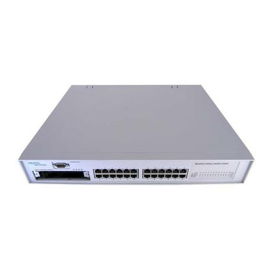
Also, a mixed, or hybrid, stack does not support multiple Spanning Tree Groups (STG). You have a single instance of STG when working with a mixed stack. Physical description Figure 1 depicts the front and side views of the Business Policy Switch. Using the Business Policy Switch 2000 Version 2.0... -
Page 40: Front Panel
Figure 1 Business Policy Switch 2000 9713FA Front panel Figure 2 shows the front-panel configuration for the Business Policy Switch 2000. Descriptions of the front-panel components follow the figure. For descriptions of the back-panel Business Policy Switch components, see “Back panel”... -
Page 41: Console Port
Table 1 Business Policy Switch 2000 front-panel description (continued) Port connectors LED display panel Console port The console port allows you to access the console interface (CI) screens and customize your network using the supplied menus and screens (see Chapter 3). - Page 42 The 10BASE-T/100BASE-TX switch ports also support half- and full-duplex mode operation (refer to Installing the Business Policy Switch 2000). The 10BASE-T/100BASE-TX RJ-45 ports can connect to 10 Mb/s or 100 Mb/s Ethernet segments or nodes.
-
Page 43: Led Display Panel
LED display panel Figure 3 shows the Business Policy Switch LED display panel. See Table 2 for a description of the LEDs. Figure 3 Business Policy Switch 2000 LED display panel Business Policy Switch 2000 10/100 Activity Status Dwn 10/100... - Page 44 Table 2 Business Policy Switch 2000 LED descriptions (continued) Label Type Color State Meaning Cas Up Stack mode The switch is in standalone mode. Green The switch is connected to the upstream unit’s Cascade A In connector. Amber This unit has detected a problem with the switch connected to the cascade up connector.
- Page 45 Table 2 Business Policy Switch 2000 LED descriptions (continued) Label Type Color State Meaning Base Base mode Green The switch is configured as the stack base unit. The switch is not configured as the stack base unit (or is in standalone mode).
-
Page 46: Back Panel
Table 2 Business Policy Switch 2000 LED descriptions (continued) Label Type Color State Meaning Link Link status Green Valid communications link established. The communications link connection is bad or there is no connection to this port. Blinking The corresponding port is management disabled. -
Page 47: Figure 5 Removing The Cascade Module Filler Panel
Cascade Module slot (Figure For more information about cascade modules, see Installing the Cascade 400-ST1 Cascade Module. See your Nortel Networks sales representative for cascade module ordering information. Figure 5 Removing the cascade module filler panel 9744FA Using the Business Policy Switch 2000 Version 2.0... -
Page 48: Cooling Fans
Figure 1 on page 40.) When you install the switch, be sure to allow enough space on both sides of the switch for adequate air flow. See Installing the Business Policy Switch 2000 for detailed information. AC power receptacle The AC power receptacle accepts the AC power cord (supplied). For installation outside of North America, make sure that you have the proper power cord for your region. -
Page 49: Redundant Power Supply Unit (Rpsu) And Uninterruptible Power Supply (Ups)
(UPS) The redundant power supply connector allows you to connect a backup power supply unit to the Business Policy Switch. Nortel Networks provides an optional redundant power supply unit (RPSU) for this purpose. The BayStack 10 Power Supply Unit is a hot-swappable power supply unit that provides uninterrupted operation to as many as four Business Policy Switches in the event that any of the switch power supplies fail. -
Page 50: Features
BayStack 10 Power Supply Unit and 200 Watt AC/DC Power Supply Module. The 100 Watt DC-DC Converter provides a plug-and-play redundant power supply unit for the Business Policy Switch 2000, as well as other products available from Nortel Networks. Contact your Nortel Networks sales representative for information about the Nortel Networks products that use the 100 Watt DC-DC Converter. - Page 51 “Port mirroring (conversation steering)” on page 86 — “Autosensing and autonegotiation” on page 86 — “BootP automatic IP configuration/MAC address” on page 87 — “SNMP MIB support” on page 89 — “SNMP trap support” on page 90 Using the Business Policy Switch 2000 Version 2.0...
-
Page 52: Support For Bps 2000-1Gt, Bps 2000-2Gt, And Bps 2000-2Ge Mdas
With version 2.0, the BPS 2000 supports the shaping, or traffic shaping, feature of IETF Differentiated Services (DiffServ) Quality of Service (QoS) architecture on a standalone BPS 2000 set to Pure BPS 2000 Stack operational mode. Using the Business Policy Switch 2000 Version 2.0... -
Page 53: Qos Filtering Of Multiple Vlans
Quality of Service (QoS). For information on configuring policy-enabled networks, DiffServ, and QoS, refer to Using Web-based Management for the Business Policy Switch 2000 Software Version 2.0, Reference for the Business Policy Switch 2000 Command Line Interface Software Version 2.0, and Reference for the Business Policy Switch 2000 Management Software Version 2.0. -
Page 54: Port Naming
2.0. This feature provides easy identification of the connected users. For information on naming ports, refer to Using Web-based Management for the Business Policy Switch 2000 Software Version 2.0, and Reference for the Business Policy Switch 2000 Command Line Interface Software Version 2.0. -
Page 55: Ip Address For Each Unit In A Stack
You must use either the console interface (CI) menus or the CLI to configure the IP addresses for each unit within a stack. Refer to Chapter 3 and Reference for the Business Policy Switch 2000 Command Line Interface Software Version 2.0 for information on configuring IP addresses for each unit in the stack from a single connection. -
Page 56: Cli Management System
You can also work with the CLI all at once, when you use the CLI command to configure the network. Refer to Reference for the Business Policy Switch 2000 Command Line Interface Software Version 2.0 for complete information on accessing the CLI and all commands. -
Page 57: Multiple Spanning Tree Protocol Groups
BPS 2000 Stack mode. To view and set the Stack Operational Mode, refer to Chapter 3, Using Web-based Management for the Business Policy Switch 2000 Software Version 2.0, or Reference for the Business Policy Switch 2000 Command Line Interface Software Version 2.0.You have only the single default STG available if you are in Hybrid Stack mode, which is for running mixed stacks. -
Page 58: Stg Configuration Guidelines
This section provides important information on configuring STGs: • An STG must be created in the following order: — Create the STG — Add the existing VLAN and port memberships — Enable the STG Using the Business Policy Switch 2000 Version 2.0... - Page 59 STG. • When a tagged port belongs to more than one STG, the egress BPDUs are tagged to distinguish the BPDUs of one STG from those of another STG. Using the Business Policy Switch 2000 Version 2.0...
- Page 60 STG1 because VLAN2 is still a member of STG1. • An STG cannot be deleted until you disable it. Additionally, you cannot delete an STG while it contains VLAN members, so you must first delete the VLANs from the STG. Using the Business Policy Switch 2000 Version 2.0...
-
Page 61: Spanning Tree Fast Learning
(The maximum size for an ASCII configuration file is 100 KBs; larger configuration files must be split into multiple files.) Using the Business Policy Switch 2000 Version 2.0... -
Page 62: Sample Ascii Configuration File
! add several MLTs and enable ! ------------------------------------------------------- mlt 3 name lag3 enable member 13-14 mlt 4 name lag4 enable member 15-16 mlt 5 name lag5 enable member 17-18 ! ------------------------------------------------------- ! add vlans and ports Using the Business Policy Switch 2000 Version 2.0... - Page 63 ! ------------------------------------------------------- ! Examples of changing interface parameters ! ------------------------------------------------------- ! change speed of port 3 interface Fastethernet 3 speed 10 duplex half exit ! change speed of port 4 interface Fastethernet 4 Using the Business Policy Switch 2000 Version 2.0...
-
Page 64: Ip Manager List
Note: To add comments to the ASCII configuration file, add an exclamation point (!) to the beginning of the line. Refer to Reference for the Business Policy Switch 2000 Command Line Interface Software Version 2.0 for complete information on using the CLI commands. -
Page 65: Policy-Enabled Networks With Qos Metering
For information on configuring the IP manager list, refer to Chapter 3, Using Web-based Management for the Business Policy Switch 2000 Software Version 2.0, and Reference for the Business Policy Switch 2000 Command Line Interface Software Version 2.0. Policy-enabled networks with QoS metering With version 1.1, the BPS 2000 supports the traffic policing, or metering, feature... -
Page 66: Eapol-Based Security
Console Interface (CI) menus, refer to Chapter 3. To configure this feature using the Web-based management system, refer to Using Web-based Management for the Business Policy Switch 2000 Software Version 2.0. To use Device Manager (DM) to configure EAPOL-based security, refer to Reference for the Business Policy Switch 2000 Management Software Version 2.0. -
Page 67: Automatic Pvid
Web-based Management for the Business Policy Switch 2000 Software Version 2.0 for information on configuring this feature using the Web-based management system. And, refer to Reference for the Business Policy Switch 2000 Command Line Interface Software Version 2.0 for information on configuring Automatic PVID with CLI commands. -
Page 68: Figure 6 Vlan Broadcast Domains Within The Switch
The PVID/VLAN association for ports 2, 4, and 10 is: PVID = 2. • Ports 2, 4, 10, 8, 6, and 11 are untagged members of VLAN 3. The PVID/VLAN association for port 8 is: PVID = 3. Using the Business Policy Switch 2000 Version 2.0... -
Page 69: Tabular Port Statistics
Business Policy Switch 2000 Software Version 2.0 for information on configuring this feature using the Web-based management system. And, refer to Reference for the Business Policy Switch 2000 Command Line Interface Software Version 2.0 for information on configuring Automatic PVID with CLI commands. Refer to Reference for the Business Policy Switch 2000 Management Software Version 2.0... -
Page 70: Bootp Menu Item For A Stack Of Only Bps 2000 Switches
BPS 2000 set to the Pure BPS 2000 Stack operational mode. Note: You must use the BPS 2000-1GT, BPS 2000-2GT, or BPS 2000-2GE MDA in a Business Policy Switch in order to be able to configure the shaping features of QoS. Using the Business Policy Switch 2000 Version 2.0... -
Page 71: Virtual Local Area Networks (Vlans)
The Business Policy Switch 2000 uses DiffServ to manage network traffic and resources. The information that is required to support DiffServ and multi-field classification is transferred using the Common Open Policy Services (COPS) protocol. COPS is a query and response protocol that exchanges policy information messages using the Transmission Control Protocol (TCP). - Page 72 Policy-based VLANs are determined by the information within the packet. A port can be a member of multiple policy-based VLANs. The order in which the rules for VLAN classification are applied are: Using the Business Policy Switch 2000 Version 2.0...
- Page 73 Independent VLAN Learning (IVL) mode—Each VLAN uses a unique forwarding database. The IVL mode is only an option when using the Business Policy Switch 2000; you must use the SVL mode when operating a hybrid stack. Business Policy Switches support up to 64 VLANs (port-, protocol-, or MAC SA-based), including VLAN #1 which is always port-based.
-
Page 74: Using 256 Vlans
Pure BPS 2000 Stack mode, and not in Hybrid Stack mode. For information on viewing and setting the stack operational mode, refer to Chapter 3, Using Web-based Management for the Business Policy Switch 2000 Software Version 2.0, or Reference for the Business Policy Switch 2000 Management Software Version 2.0. Refer to Chapter 2, “Network... -
Page 75: Security
2.0. To use Device Manager (DM) to configure VLANs, refer to Reference for the Business Policy Switch 2000 Management Software Version 2.0. And, to configure this feature using CLI commands, refer to Reference for the Business Policy Switch 2000 Command Line Interface Software Version 2.0. -
Page 76: Figure 7 Business Policy Switch 2000 Security Feature
Figure 7 Business Policy Switch 2000 security feature RADIUS server To Network Center RADIUS-based Switch security Teachers’ offices Student Dormitory and classrooms Legend Library = Secure locked area BS45077A In this configuration example, the following security measures are implemented: •... - Page 77 The exception is the printer, which is assigned as a single station with full bandwidth to that port. It is assumed that all PCs are password protected and that access to the library is physically secured. Using the Business Policy Switch 2000 Version 2.0...
-
Page 78: Radius-Based Network Security
This feature is available only with BPS2000 software version 2.0 and higher. Also, this feature is unavailable on the BayStack 450 or 410 switches. In a Hybrid stack, only the BPS 2000 will filter the specified MAC DAs. Using the Business Policy Switch 2000 Version 2.0... - Page 79 MAC DAs you want filtered. For instructions on configuring the MAC address-based security feature, refer to Chapter 3, Using Web-based Management for the Business Policy Switch 2000 Software Version 2.0, Reference for the Business Policy Switch 2000 Management Software Version 2.0, and Reference for the Business Policy Switch 2000 Command Line Interface Software Version 2.0.
-
Page 80: Eapol-Based Security
Interface (CI) menus, refer to Chapter 3. To configure this feature using the Web-based management system, refer to Using Web-based Management for the Business Policy Switch 2000 Software Version 2.0. To use Device Manager (DM) to configure EAPOL-based security, refer to Reference for the Business Policy Switch 2000 Management Software Version 2.0. - Page 81 Chapter 1 The Business Policy Switch 2000 81 • Authenticator—software with the sole purpose of authorizing a supplicant that is attached to the other end of a LAN segment. • Authentication Server—a RADIUS server that provides authorization services to the Authenticator.
- Page 82 82 Chapter 1 The Business Policy Switch 2000 EAPOL dynamic VLAN assignment If EAPOL-based security is enabled on a port, and then the port is authorized, the EAPOL feature dynamically changes the port’s VLAN configuration according to preconfigured values, and assigns a new VLAN. The new VLAN configuration values are applied according to previously stored parameters (based on the user_id) in the Authentication server.
- Page 83 • At least one of the following supported switches: — BayStack 350/410-24T/450 switch (software version V4.0, or later) — Business Policy Switch 2000 (software version V1.1, or later) • RADIUS server (Microsoft Windows XP Server) • Client software that supports EAPOL (Microsoft Windows XP Client) You must specify the Microsoft 2001 IAS server (or any generic RADIUS server that supports EAP) as the primary RADIUS server for these devices.
-
Page 84: Flash Memory Storage
84 Chapter 1 The Business Policy Switch 2000 EAPOL-based security configuration rules The following configuration rules apply to your BPS 2000 when using EAPOL-based security: • Before configuring your switch, you must configure the Primary RADIUS Server and Shared Secret fields. -
Page 85: Configuration Parameters Storage
For information on configuring MultiLink Trunks using the CI menus, refer to Chapter 3. To configure this feature using the Web-based management system, refer to Using Web-based Management for the Business Policy Switch 2000 Software Version 2.0. To use Device Manager (DM) to configure this feature, refer to Reference for the Business Policy Switch 2000 Management Software Version 2.0. -
Page 86: Port Mirroring (Conversation Steering)
MAC addresses is monitored. You can attach a probe device (such as a Nortel Networks StackProbe, or equivalent) to the designated monitor port For more information about the port mirroring feature, refer to Chapter 2, “Network... -
Page 87: Bootp Automatic Ip Configuration/Mac Address
For information on configuring autonegoitation using the CI menus, refer to Chapter 3. To configure this feature using the Web-based management system, refer to Using Web-based Management for the Business Policy Switch 2000 Software Version 2.0. To use Device Manager (DM) to configure this feature, refer to Reference for the Business Policy Switch 2000 Management Software Version 2.0. -
Page 88: Configuration And Switch Management
Java-based Device Manager Device Manager is a Java-based set of graphical network management applications used to configure and manage a Business Policy Switch. Refer to Reference for the Business Policy Switch 2000 Management Software Operations Software Version 2.0 for more information. •... -
Page 89: Multifield Packet Classification
BPS 2000. Use the CLI through a Telnet connection or through the serial port on the console. Refer to Reference for the Business Policy Switch 2000 Command Line Interface Software Version 2.0 for complete information on using the CLI. -
Page 90: Snmp Trap Support
90 Chapter 1 The Business Policy Switch 2000 Table 5 SNMP MIB support (continued) Application Standard MIBs Proprietary MIBs RMON rfc2819.mib rcMLT Common Open Policy Service rfc.2940.mib (COPS) support Policy Management Policy Info Base pib802, pibFramework, pibIp, pibNtn, mibntqos, pibNtnEvol... -
Page 91: Supported Standards And Rfcs
Using Web-based Management for the Business Policy Switch 2000 Software Version 2.0, Reference for the Business Policy Switch 2000, Command Line Interface Software Version 2.0, and Reference for the Business Policy Switch 2000 Management Software Version 2.0. Supported standards and RFCs This section lists the standards and RFCs supported by the BPS 2000. -
Page 92: Rfcs
92 Chapter 1 The Business Policy Switch 2000 RFCs For more information about networking concepts, protocols, and topologies, consult the following RFCs: • RFC 1213 (MIB-II) • RFC 1493 (Bridge MIB) • RFC 2863 (Interfaces Group MIB) • RFC 2665 (Ethernet MIB) •... -
Page 93: Network Configuration
When you are using a local console to access the BPS 2000 software version 2.0 features with a Hybrid, or mixed, stack (BPS 2000 and BayStack 450 and 410 switches in the same stack), you must plug your local console into a BPS 2000 unit. Using the Business Policy Switch 2000 Version 2.0... -
Page 94: Network Configuration Examples
94 Chapter 2 Network configuration To find out which version of the BPS 2000 software is running, use the console interface (CI) menus or the Web-based management system: • CI menus—From the main menu of the console, choose Systems Characteristics menu. The software currently running is displayed in sysDescr. -
Page 95: Desktop Switch Application
Before segmentation, 88 users had a total bandwidth of only 10 Mb/s available. After segmentation, 92 users have 40 Mb/s, four times the previous bandwidth, while adding 22 dedicated 100 Mb/s connections. This configuration can be extended to add more segments without degrading performance. Using the Business Policy Switch 2000 Version 2.0... -
Page 96: Figure 9 Business Policy Switch Used As A Segment Switch
96 Chapter 2 Network configuration Figure 9 Business Policy Switch used as a segment switch Server After Before Business Policy Switch 2000 10BASE-T hubs Up to 22 users Server Up to 23 users Up to 23 users Up to 23... -
Page 97: High-Density Switched Workgroup Application
100BASE-TX hub, and a 100 Mb/s server as well as 10 Mb/s connections to DTE (data terminal equipment). See the Nortel Networks library Web page www.nortelnetworks.com/ documentation for online documentation about the Nortel Networks Passport 1100 switch and the BayStack 303 and BayStack 304 switches. Using the Business Policy Switch 2000 Version 2.0... -
Page 98: Fail-Safe Stack Application
98 Chapter 2 Network configuration Figure 10 Configuring power workgroups and a shared media hub Business Policy Switch 2000 BayStack 303 switch Server 100BASE-TX CPU PS1 PS2 FAN Accelar 1100 switch BayStack 304 switch 10 Mb/s 100 Mb/s 1000 Mb/s (Gigabit) 9841EA Fail-safe stack application... -
Page 99: Business Policy Switch Stack Operation
“Fail-safe stack application.”). The entire stack is manageable as a single unit. Installation instructions are provided with the BayStack 400-ST1 Cascade Module (see your Nortel Networks sales representative for ordering information). This section discusses the following stacking topics: • “BayStack 400-ST1 Cascade Module” on page 100 •... -
Page 100: Baystack 400-St1 Cascade Module
100 Chapter 2 Network configuration • “Stack configurations” on page 104 • “Redundant cascade stacking feature” on page 108 Note: If you are implementing a mixed stack with the Business Policy Switch and BayStack 450 and BayStack 410 switches, refer to Appendixes for configuration and interoperability information. -
Page 101: Unit Select Switch
Figure 13). Figure 13 Connecting cascade cables Cascade A Out Cascade A In Unit 1 Unit 2 9812EA Base unit 303978-A cascade cable 303978-A cascade cable (used for return) Using the Business Policy Switch 2000 Version 2.0... -
Page 102: Base Unit
102 Chapter 2 Network configuration Base unit Note: For stacking three or more units (maximum 8 units per stack), order the optional 1 meter (39.27 inch) cascade max-return cable (order number AL2018001). The base unit is the unique stack unit that you configure with the Unit Select switch on the front panel of the BayStack 400-ST1 Cascade Module. -
Page 103: Stack Mac Address
This process can continue until there are only two units left in the stack configuration. Using the Business Policy Switch 2000 Version 2.0... -
Page 104: Removing A Unit From The Stack
104 Chapter 2 Network configuration Removing a unit from the stack If a unit is removed from the stack (therefore operating in standalone mode), the following switch configuration settings revert back to the settings configured before the unit became a member of the stack: •... -
Page 105: Figure 14 Stack Up Configuration Example
Unit 1 9813EA Table 7 describes the stack up configuration illustration references. Table 7 Stack up configuration description Last unit Base unit Cascade Cable (part number 303978-A) Cascade Cable (part number 303979-A) Using the Business Policy Switch 2000 Version 2.0... -
Page 106: Stack Down Configurations
106 Chapter 2 Network configuration Stack down configurations Figure 15, data flows from the base unit (unit 1) to the next switch, which is assigned as unit 2, and continues until the last switch in the stack is assigned as unit 8. -
Page 107: Table 8 Stack Down Configuration Description
(GUI) that represents the stack (see Figure 15). Note: For this reason, Nortel Networks recommends that you always configure the top unit in the stack as the base unit. In any stack configuration, the following applies: •... -
Page 108: Redundant Cascade Stacking Feature
108 Chapter 2 Network configuration Redundant cascade stacking feature Business Policy Switches allow you to connect up to 8 units into a redundant cascade stack. If any single unit fails or if a cable is accidently disconnected, other units in the stack remain operational, without interruption. Figure 16 shows an example of how a stack configuration reacts to a failed or powered-down unit in the stack configuration:... -
Page 109: Figure 16 Redundant Cascade Stacking Feature
Unit 5 9815EA Table 9 describes the redundant cascade stacking illustration references. Table 9 Redundant cascade stacking descriptions Base unit Last unit Cascade cable (part number 303978-A) Cascade max-return cable (part number 303979-A) Using the Business Policy Switch 2000 Version 2.0... -
Page 110: Ieee 802.1Q Vlan Workgroups
110 Chapter 2 Network configuration IEEE 802.1Q VLAN workgroups Note: For guidelines on configuring VLANs, STGs, and MLT, refer to Chapter 1. Business Policy Switches support up to 64 VLANs (maximum of 48 MAC source address-based VLANs) with IEEE 802.1Q tagging available per port. With software version 1.2, the BPS 2000 supports up to 256 VLANs (maximum of 48 MAC source addressed-based VLANs.) Note: Only standalone or pure stacks of BPS 2000 support 256 VLANs. -
Page 111: Ieee 802.1Q Tagging
Refer to Chapter 3, Using Web-based Management for the Business Policy Switch 2000 Software Version 2.0, Reference for the Business Policy Switch 2000 Command Line Interface Software Version 2.0, and Reference for the Business Policy Switch 2000 Management Software Version 2.0 for information on overriding the default values. - Page 112 112 Chapter 2 Network configuration • Untagged frame— a frame that does not carry any VLAN tagging information in the frame header. • VLAN port members— a set of ports that form a broadcast domain for a specific VLAN. A port can be a member of one or more VLANs. •...
-
Page 113: Figure 18 Default Vlan Settings
18, untagged incoming packets are assigned directly to VLAN 2 (PVID = 2). Port 5 is configured as a tagged member of VLAN 2, and port 7 is configured as an untagged member of VLAN 2. Using the Business Policy Switch 2000 Version 2.0... -
Page 114: Figure 19 Port-Based Vlan Assignment
114 Chapter 2 Network configuration Figure 19 Port-based VLAN assignment Port 1 Port 2 Port 3 Tagged member PVID = 2 of VLAN 2 Untagged packet 802.1Q Switch Data Before Port 6 Port 7 Port 8 Untagged member of VLAN 2 BS45011A As shown in Figure... -
Page 115: Figure 21 Policy-Based Vlan Assignment
VID = 3 Untagged member of VLAN 3 16 bits 3 bits 1 bits 12 bits Data After Outgoing untagged packet (unchanged) Priority - User_priority - Canonical format indicator - VLAN identifier BS45012B Using the Business Policy Switch 2000 Version 2.0... -
Page 116: Figure 23 802.1Q Tag Assignment
116 Chapter 2 Network configuration Figure 23, tagged incoming packets are assigned directly to VLAN 2 because of the tag assignment in the packet. Port 5 is configured as a tagged member of VLAN 2, and port 7 is configured as an untagged member of VLAN 2. Figure 23 802.1Q tag assignment Port 1 Port 2... -
Page 117: Vlans Spanning Multiple Switches
VLANs that span multiple switches, without interfering with the Spanning Tree Protocol. Refer to Chapter 1 for additional guidelines on configuring VLANs and spanning tree groups. Using the Business Policy Switch 2000 Version 2.0... -
Page 118: Vlans Spanning Multiple 802.1Q Tagged Switches
118 Chapter 2 Network configuration VLANs spanning multiple 802.1Q tagged switches Figure 25 shows VLANs spanning two Business Policy Switches. The 802.1Q tagging is enabled on S1, port 2 and on S2, port 1 for VLAN 1 and VLAN 2. Both ports are tagged members of VLAN 1 and VLAN 2. -
Page 119: Figure 26 Vlans Spanning Multiple Untagged Switches
To connect multiple VLANs across switches with redundant links, you must disable the STP on all participating switch ports. Figure 27 shows possible consequences of enabling the STP when using VLANs between untagged (non-802.1Q tagged) switches. Using the Business Policy Switch 2000 Version 2.0... -
Page 120: Shared Servers
120 Chapter 2 Network configuration Figure 27 Possible problems with VLANs and Spanning Tree Protocol Station A Business Policy Switch 2000 VLAN 1 VLAN 2 Forwarding Blocking Communications Business Policy Switch 2000 VLAN 1 VLAN 2 Station B 9801EA As shown in Figure 27, with STP enabled, only one connection between Switch S1 and Switch S2 is forwarding at any time. -
Page 121: Figure 28 Multiple Vlans Sharing Resources
This arrangement allows the switch to establish the appropriate broadcast domains within the switch (Figure 29). Refer to Chapter 1 for additional guidelines on configuring VLANs and spanning tree groups. Using the Business Policy Switch 2000 Version 2.0... -
Page 122: Figure 29 Vlan Broadcast Domains Within The Switch
122 Chapter 2 Network configuration Figure 29 VLAN broadcast domains within the switch VLAN 3 VLAN 2 VLAN 1 Port 2 Port 4 Port 10 Port 8 Port 6 Port 11 PVID = 2 PVID = 3 PVID = 1 VLAN 1 (PVID = 1) VLAN 2 (PVID = 2) VLAN 3 (PVID = 3) -
Page 123: Figure 30 Default Vlan Configuration Screen Example
VLAN 1. Figure 31 shows the VLAN Configuration screen after it is configured to support the VLAN 3 broadcast domain shown in Figure 29 (VLAN Name is optional). Using the Business Policy Switch 2000 Version 2.0... -
Page 124: Figure 31 Vlan Configuration Screen Example
124 Chapter 2 Network configuration Ports 2, 4, 6, 8, 10, and 11 are now untagged members of VLAN 3 as shown in Figure 29 page 122. Figure 31 VLAN Configuration screen example VLAN Configuration Create VLAN: Vlan Type: [ Port-Based ] Delete VLAN: Protocol Id (PID): [ None... -
Page 125: Figure 32 Default Vlan Port Configuration Screen Example
VLAN Port Configuration screen after it is configured to support the PVID assignment for port 8, as shown in Figure 29 (Port Name is optional). The PVID/VLAN association for VLAN 3 is now PVID = 3. Using the Business Policy Switch 2000 Version 2.0... -
Page 126: Vlan Workgroup Summary
126 Chapter 2 Network configuration Figure 33 VLAN Port Configuration screen example VLAN Port Configuration Unit: Port: Filter Tagged Frames: [ No Filter Untagged Frames: [ No Filter Unregistered Frames: [ No Port Name: [ Student port ] PVID: Port Priority: Tagging: [Untagged Access] AutoPVID (all ports):... -
Page 127: Figure 34 Vlan Configuration Spanning Multiple Switches
Both ports are tagged Untagged ports members of VLAN 1 (STP disabled) and VLAN 2 Business Policy Switch 2000 Non-802.1Q tagging switch VLAN 1 (PVID=1) VLAN 2 (PVID=2) VLAN 3 (PVID=3) 9802EA Using the Business Policy Switch 2000 Version 2.0... -
Page 128: Vlan Configuration Rules
128 Chapter 2 Network configuration VLAN configuration rules VLANs operate according to specific configuration rules. When creating VLANs, consider the following rules that determine how the configured VLAN reacts in any network topology: • You must be in the Pure BPS 2000 Stack mode and using software version 1.2 to be able to configure between 65 and 256 VLANs. - Page 129 IP Multicast can be optimized in a LAN by using IP Multicast filtering switches, such as the Business Policy Switch. As shown in Figure 35, a non-IP Multicast filtering switch causes IP Multicast traffic to be sent to all segments on the local subnet. Using the Business Policy Switch 2000 Version 2.0...
-
Page 130: Figure 35 Ip Multicast Propagation With Igmp Routing
130 Chapter 2 Network configuration Figure 35 IP Multicast propagation with IGMP routing Host membership query IGMP Host Host Internet membership query Designated router #1 Designated router #2 Non-IP Multicast filtering switch Multicast stream Host Non-IP Multicast membership filtering switch report Host membership... -
Page 131: Figure 36 Business Policy Switch Filtering Ip Multicast Streams (1 Of 2)
In this way, the router receives a single consolidated report from that entire subnet. Using the Business Policy Switch 2000 Version 2.0... -
Page 132: Figure 37 Business Policy Switch Filtering Ip Multicast Streams (2 Of 2)
132 Chapter 2 Network configuration After the switches learn which ports are requesting access to the IP Multicast stream, all other ports not responding to the queries are blocked from receiving the IP Multicast (Figure 37). Figure 37 Business Policy Switch filtering IP multicast streams (2 of 2) Internet Designated router... -
Page 133: Igmp Snooping Configuration Rules
For more information about using the IGMP snooping feature, refer to Chapter 1 for additional guidelines on configuring VLANs, IGMP, and spanning tree groups and Chapter 3. See also appendixes for configuration flowcharts that can help you use this feature. Using the Business Policy Switch 2000 Version 2.0... -
Page 134: Ieee 802.1P Prioritizing
134 Chapter 2 Network configuration IEEE 802.1p prioritizing For more information on prioritizing traffic, refer to Chapter 4, “Policy-enabled networks.” You can use the VLAN Configuration screens to prioritize the order in which the switch forwards packets, on a per-port basis. For example, if messages from a specific segment are crucial to your operation, you can set the switch port connected to that segment to a higher priority level (by default, all switch ports are set to low priority). -
Page 135: Multilink Trunks
You can use the Trunk Configuration screen with the CI menus, the Web-based management system, the CLI, or DM to create switch-to-switch and switch-to-server MultiLink Trunk links. Figure 39 shows two trunks (T1 and T2) connecting Switch S1 to switches S2 and S3. Using the Business Policy Switch 2000 Version 2.0... -
Page 136: Figure 39 Switch-To-Switch Trunk Configuration Example
136 Chapter 2 Network configuration Figure 39 Switch-to-switch trunk configuration example Business Policy Switch 2 Business Policy Switch 2000 Business Policy Switch 2 9804EA You can configure each of the trunks shown in Figure 39 with up to four switch ports to provide up to 800 Mb/s aggregate bandwidth through each trunk, in full-duplex mode. -
Page 137: Client/Server Configuration Using Multilink Trunks
T2 and T3 into separate VLANs for this configuration to function properly For more information on configuration guidelines for spanning tree, VLANs, and MultiLink Trunking, refer to Chapter 1 and “IEEE 802.1Q VLAN workgroups.” Using the Business Policy Switch 2000 Version 2.0... -
Page 138: Before You Configure Trunks
138 Chapter 2 Network configuration Figure 41 Client/server configuration example Business Policy Switch 2000 Business Business Business Policy Switch 2000 Policy Switch 2000 Policy Switch 200 9806EA For detailed information about configuring trunks, see Chapter 3. Before you configure trunks When you create and enable a trunk, the trunk members (switch ports) take on certain settings necessary for correct operation of the MultiLink Trunking feature. -
Page 139: Multilink Trunking Configuration Rules
When a trunk is enabled, the trunk spanning tree participation setting takes precedence over that of any trunk member. • If you change the VLAN settings of any trunk member, the VLAN settings of all members of that trunk change similarly. Using the Business Policy Switch 2000 Version 2.0... -
Page 140: How The Multilink Trunk Reacts To Losing Distributed Trunk Members
If you change the IGMP snooping configuration for any trunk member, the IGMP snooping settings for all trunk members change. • Nortel Networks recommends that you do not enable MAC Address Security (or BaySecure) on trunk ports. How the MultiLink Trunk reacts to losing distributed trunk... -
Page 141: Spanning Tree Considerations For Multilink Trunks
100 Mb/s and two at 10 Mb/s. Trunk T1 provides an aggregate bandwidth of 220 Mb/s. The Path Cost for T1 is 4 (Path Cost = 1000/ Using the Business Policy Switch 2000 Version 2.0... -
Page 142: Figure 43 Path Cost Arbitration Example
(T1) to determine the most efficient path. Also, the trunk cannot span multiple spanning tree groups. Figure 43 Path Cost arbitration example Business Business Policy Switch 2000 Policy Switch 2000 100 Mb/s 100 Mb/s 100 Mb/s... -
Page 143: Figure 44 Example 1: Correctly Configured Trunk
If Switch S2’s trunk member port 11 is physically disconnected and then reconnected to port 13, the Spanning Tree Port Configuration screen for Switch S1 changes to show port 6 in the Blocking state (Figure 45). Using the Business Policy Switch 2000 Version 2.0... -
Page 144: Additional Tips About The Multilink Trunking Feature
144 Chapter 2 Network configuration Figure 45 Example 2: detecting a misconfigured port [Blocking] S1 Port Configuration screen Business Policy Switch 2 Business Policy Switch 2000 S2 Port Configuration screen 9809EA Additional tips about the MultiLink Trunking feature When you create a MultiLink Trunk, the individual trunk members (the specific ports that make up the trunk) logically connect and react as a single entity. -
Page 145: Port Mirroring
Note: A probe device, such as the Nortel Networks StackProbe ™ equivalent, must be connected to the designated monitor port to use this feature (contact your Nortel Networks sales agent for details about the StackProbe). The following sections provide sample configurations for both monitoring modes available with the Port Mirroring feature: Using the Business Policy Switch 2000 Version 2.0... -
Page 146: Port-Based Mirroring Configuration
146 Chapter 2 Network configuration • Port-based mirroring • Address-based mirroring A sample Port Mirroring Configuration screen accompanies each network configuration example. Note that the displayed screens do not show all of the screen prompts that precede some actions. Note: Use the CI menus, the CLI, or the Web-based management system to configure port mirroring. -
Page 147: Figure 46 Port-Based Mirroring Configuration Example
Monitor all traffic received by port X (destined to port Y) and then transmitted by port Y. • Monitor all traffic received/transmitted by port X and transmitted/received by port Y (conversations between port X and port Y). Using the Business Policy Switch 2000 Version 2.0... -
Page 148: Figure 47 Port Mirroring Configuration Port-Based Screen Example
148 Chapter 2 Network configuration As shown in the Port Mirroring Configuration screen example (Figure 47), port 23 is designated as the Monitor Port for ports 24 and 25 in Switch S1. Note: The Unit value (in the Unit/Port field) is not configurable when the switch is operating standalone. -
Page 149: Address-Based Mirroring Configuration
Monitor all traffic received by address A from any address. • Monitor all traffic received by or transmitted by address A. • Monitor all traffic transmitted by address A to address B. Using the Business Policy Switch 2000 Version 2.0... - Page 150 150 Chapter 2 Network configuration • Monitor all traffic between address A and address B (conversation between the two stations). Figure 49 shows the Port Mirroring Configuration screen setup for this example. In this example, port 23 becomes the designated Monitor Port for Switch S1 when you press Enter in response to the [Yes] screen prompt.
-
Page 151: Port Mirroring Configuration Rules
When you create a port-based port mirroring configuration, be sure that the monitor port and both of the mirrored ports, port X and port Y, have the same configuration. Use the VLAN Configuration screen to configure the VLAN (see Chapter 3). Using the Business Policy Switch 2000 Version 2.0... -
Page 152: Chapter 3
152 Chapter 2 Network configuration • VLAN configuration settings for any ports configured for port-based mirroring cannot be changed. Use the Port Mirroring Configuration screen to disable port mirroring (or reconfigure the port mirroring ports), then change the VLAN configuration settings. •... -
Page 153: Using The Console Interface
Characteristics menu. The software currently running is displayed in sysDescr. • Web-based management system—Open the System Information page, which is under Administration on the main menu. The software currently running is displayed in the sysDescription field. Using the Business Policy Switch 2000 Version 2.0... -
Page 154: Accessing The Ci Menus And Screens
154 Chapter 3 Using the console interface You can use 256 port-, protocol-, and MAC SA-based VLANs for the stack with a Pure BPS 2000 stack running software version 1.2 or higher. (The maximum number of MAC SA-based VLANs is 48.) If you are working with a mixed, or hybrid, stack, you can use 64 VLANs for the entire stack. -
Page 155: Using The Ci Menus And Screens
Navigating the CI menus and screens Use the following methods to navigate the CI menus and screens. To select a menu option: Use the arrow keys to highlight the option name. Press [Enter]. Using the Business Policy Switch 2000 Version 2.0... -
Page 156: Screen Fields And Descriptions
156 Chapter 3 Using the console interface The option takes effect immediately after you press [Enter]. Alternatively, you can press the key corresponding to the underlined letter in the option name. For example, to select the Switch Configuration option in the main menu, press the w key. -
Page 157: Figure 51 Map Of Console Interface Screens
Port Configuration screen. Note: The field values shown in the CI screens in this section are provided as examples only. Using the Business Policy Switch 2000 Version 2.0... -
Page 158: Main Menu
However, the full menu options are shown in the screen examples and described in the following sections. Figure 52 Console interface main menu Business Policy Switch 2000 Main Menu IP Configuration/Setup... SNMP Configuration... System Characteristics... -
Page 159: Table 10 Console Interface Main Menu Options
Telnet session. This screen also allows you to set the switch to allow up to 10 IP addresses to access the switch using either these management systems or SNMP access Using the Business Policy Switch 2000 Version 2.0... - Page 160 • When you select this option, the switch resets, runs a self-test, then displays the Nortel Networks logo screen. Press [Ctrl]-Y to access the Business Policy Switch main menu. Reset to Default Resets the switch to the factory default configuration settings.
- Page 161 Command Line Allows a properly authorized user to initiate a CLI management session. Refer to Interface Reference for the Business Policy Switch 2000 Command Line Interface Release 2.0 for information on using the CLI. Logout Allows a user in a Telnet session or a user working at a password-protected console terminal to terminate the session.
-
Page 162: Ip Configuration/Setup Screen
162 Chapter 3 Using the console interface IP Configuration/Setup screen The IP Configuration/Setup screen (Figure 53) allows you to set or modify the Business Policy Switch IP configuration parameters. Data that you enter in the user-configurable fields takes effect as soon as you press [Enter]. To open the IP Configuration/Setup screen: ➨... -
Page 163: Table 11 Ip Configuration/Setup Screen Fields
In-Band Subnet Mask field value is not present, the software provides an in-use default value for the In-Band Subnet Mask field that is based on the class of the IP address entered in the In-Band IP Address field. Using the Business Policy Switch 2000 Version 2.0... -
Page 164: Choosing A Bootp Request Mode
164 Chapter 3 Using the console interface Table 11 IP Configuration/Setup screen fields (continued) Field Description In-Band Subnet The subnet address mask associated with the in-band IP address shown on the screen Mask (see In-Band Switch IP Address field). Network routers use the subnet mask to determine the network or subnet address portion of a host’s IP address. - Page 165 IP address. • If the switch does not receive a BootP reply, the switch cannot be managed using the in-band IP address set from the console terminal. Using the Business Policy Switch 2000 Version 2.0...
- Page 166 166 Chapter 3 Using the console interface If an IP address is not currently in use, these actions take effect immediately. If an IP address is currently in use, these actions take effect only after the switch is reset or power cycled. BootP Disabled Allows the switch to be managed only by using the IP address set from the console terminal.
-
Page 167: Snmp Configuration Screen
[ 0.0.0.0 ] Community String: Authentication Trap: [ Enabled AutoTopology: [ Enabled Enter text, press <Return> or <Enter> when complete. Press Ctrl-R to return to previous menu. Press Ctrl-C to return to Main Menu. Using the Business Policy Switch 2000 Version 2.0... -
Page 168: Table 12 Snmp Configuration Screen Fields
Disabled * The Trap IP Address and Community String fields can be set using a MIB table (in a Nortel Networks proprietary MIB). The status of the row in the MIB table can be set to Ignore. If the row status is set to Ignore, the fields appear to be set when viewed from the console terminal;... -
Page 169: System Characteristics Screen
1.3.6.1.4.1.45.3.40.1 sysUpTime: 0 days, 0:11:3 sysServices: sysContact: sysName: sysLocation: Enter text, press <Return> or <Enter> when complete. Press Ctrl-R to return to previous menu. Press Ctrl-C to return to Main Menu. Using the Business Policy Switch 2000 Version 2.0... -
Page 170: Table 13 System Characteristics Screen Fields
170 Chapter 3 Using the console interface Table 13 describes the System Characteristics screen fields. Table 13 System Characteristics screen fields Field Description Operation Mode Read-only field that indicates the operation mode of the unit, for example: • When the unit is part of a stack configuration, the (read-only) field indicates the unit is operational in a stack, and lists the current unit number of this switch. -
Page 171: Switch Configuration Menu Screen
Note: The High Speed Flow Control Configuration option only appears when an optional Gigabit MDA is installed. Choose Switch Configuration (or press w) from the main menu to open the Switch Configuration Menu screen (Table 14). Using the Business Policy Switch 2000 Version 2.0... -
Page 172: Figure 56 Switch Configuration Menu Screen
172 Chapter 3 Using the console interface Figure 56 Switch Configuration Menu screen Switch Configuration Menu MAC Address Table MAC Address Security Configuration... EAPOL Security Configuration… VLAN Configuration... Port Configuration... High Speed Flow Control Configuration... MultiLink Trunk Configuration... Port Mirroring Configuration... Rate Limiting Configuration... - Page 173 (see Chapter 1 for more information about this feature). Display Port Statistics Displays the Port Statistics screen (see “Port Statistics screen” on page 234). This screen allows you to view detailed information about any switch port. Using the Business Policy Switch 2000 Version 2.0...
-
Page 174: Mac Address Table Screen
174 Chapter 3 Using the console interface Table 14 Switch Configuration Menu screen options (continued) Option Description Clear All Port Statistics Allows you to clear all port statistics. This option is followed by screen prompts that precede a choice of the actions: •... -
Page 175: Figure 57 Mac Address Table Screen
Specifies how long a learned MAC address remains in the switch’s forwarding database. If an entry is inactive for a period of time that exceeds the specified aging time, the address is removed. Default Value 300 seconds Range 10 to 1,000,000 seconds Using the Business Policy Switch 2000 Version 2.0... -
Page 176: Mac Address Security Configuration Menu Screen
176 Chapter 3 Using the console interface Table 15 MAC Address Table screen fields (continued) Field Description Find an Address Allows the user to search for a specific MAC address. Default Value 00-00-00-00-00-00 (no MAC address assigned) Range 00-00-00-00-00-00 to FF-FF-FF-FF-FF-FF Select VLAN ID Enter the VLAN ID number you want to display the MAC addresses for. -
Page 177: Figure 58 Mac Address Security Configuration Menu Screen
Displays the MAC Address Security Port Configuration screen (see “MAC Port Configuration... Address Security Port Configuration screen” on page 181”). This screen allows you to Enable or Disable MAC Security for each port. Using the Business Policy Switch 2000 Version 2.0... - Page 178 178 Chapter 3 Using the console interface Table 16 MAC Address Security Configuration Menu Options (continued) Option Description MAC Address Security Displays the MAC Address Security Port Lists screen (see “MAC Address Port Lists... Security Port Lists screens” on page 184).
-
Page 179: Mac Address Security Configuration Screen
Current Learning Mode: [ Disabled ] Use space bar to display choices, press <Return> or <Enter> to select choice. Press Ctrl-R to return to previous menu. Press Ctrl-C to return to Main Menu. Using the Business Policy Switch 2000 Version 2.0... -
Page 180: Table 17 Mac Address Security Configuration Fields
180 Chapter 3 Using the console interface Table 17 describes the MAC Address Security Configuration screen fields. Table 17 MAC Address Security Configuration fields Field Description MAC Address Security When this field is set to enabled, the software checks source MAC addresses of packets that arrive on secure ports against MAC addresses listed in the MAC Address Security Table for allowed membership. -
Page 181: Mac Address Security Port Configuration Screen
MAC Address Security Port Configuration screen The MAC Address Security Port Configuration screens (Figure 60 Figure allow you to set or modify your MAC address port security configuration on a per port basis. Using the Business Policy Switch 2000 Version 2.0... - Page 182 182 Chapter 3 Using the console interface To open the MAC Address Security Port Configuration screen: ➨ Choose MAC Address Security Port Configuration from the MAC Address Security Configuration Menu. 208700-C...
-
Page 183: Figure 60 Mac Security Port Configuration Screen (1 Of 2)
Press Ctrl-P to display choices for ports 1-14. Use space bar to display choices, press <Return> or <Enter> to select choice. Press Ctrl-R to return to previous menu. Press Ctrl-C to return to Main Menu. Using the Business Policy Switch 2000 Version 2.0... -
Page 184: Mac Address Security Port Lists Screens
184 Chapter 3 Using the console interface Table 18 describes the MAC Security Port Configuration screen fields. Table 18 MAC Security Port Configuration screen fields Field Description Port Displays a numbered port list. Trunk Displays the trunk number if the port is a member of that trunk. Default blank field Security... -
Page 185: Figure 62 Mac Address Security Port Lists Screens
Configuration Menu. The options for allowed port access include: NONE, ALL, and ports that are specified in a list (for example, 1/1, 2/6, etc.). Refer to Port List syntax for more information. Using the Business Policy Switch 2000 Version 2.0... -
Page 186: Port List Syntax
186 Chapter 3 Using the console interface Figure 63 MAC Address Security Port Lists screen MAC Address Security Port Lists Entry Port List ----- --------- [ 1/1-7,2/1-7,2/9,3/1-4,4/12 ] [ 2/1-7,2/9,4/3-5 ] [ 1/3,2/7,3/1-4 ] [ 4/12 ] [ 1/NONE,2/NONE,3/NONE,4/NONE ] [ 1/ALL,2/ALL,3/ALL,4/ALL ] [ 3/ALL ] More... -
Page 187: Accelerator Keys For Repetitive Tasks
If you want to add another port (for example, port 2/9) to the existing port number list, you could highlight the field and then type another port list, including the new port number 1/3,2/7,2/9,3/1-4 [Return]. This method can be cumbersome. Using the Business Policy Switch 2000 Version 2.0... - Page 188 188 Chapter 3 Using the console interface As an alternative method instead, you can highlight the field and then enter +2/9 [Return]. The existing field keeps the previous list and adds the new port number (2/9) between ports 2/7 and 3/14. (If you choose to add port 2/8 to the existing port number list, the field accepts the new port 2/8 but shows the new port number list field as: 1/3,2/7-8,3/1-4.) Removing a port from an existing port number list...
-
Page 189: Mac Address Security Table Screens
Press Ctrl-R to return to previous menu. Press Ctrl-C to return to Main Menu. ➨ Choose MAC Address Security Table from the MAC Address Security Configuration Menu to open the MAC Address Security Table screen (Figure 65). Using the Business Policy Switch 2000 Version 2.0... -
Page 190: Figure 65 Mac Address Security Table Screen
190 Chapter 3 Using the console interface Figure 65 MAC Address Security Table screen MAC Address Security Table Find an Address: MAC Address Allowed Source MAC Address Allowed Source ----------- -------------- ----------- -------------- [ 44-33-22-44-55-44 ] [ S1 ] [ 22-44-33-55-66-55 ] [ S2 ] [ 22-55-33-44-33-22 ] [ S3 ]... -
Page 191: Eapol Security Configuration Screen
You can set up these parameters directly on your RADIUS server. For detailed instructions about configuring your RADIUS server, refer to your RADIUS server documentation. Note: Do not enable EAPOL security on the switch port that is connected to the RADIUS server. Using the Business Policy Switch 2000 Version 2.0... -
Page 192: Figure 66 Eapol Security Configuration Screen
192 Chapter 3 Using the console interface To open the EAPOL Security Configuration screen: ➨ Choose EAPOL Security Configuration (or press e) from the Switch Configuration Menu. Figure 66 EAPOL Security Configuration screen EAPOL Security Configuration EAPOL Administrative State: [ Disabled ] Unit: [ ] Port: [ Initialize:... - Page 193 A read-only field that shows the current authorization status for the specified unit/port. This read-only field does not appear when the Unit/Port field value is set to All. Default Authorized Range Authorized,Unauthorized Using the Business Policy Switch 2000 Version 2.0...
- Page 194 194 Chapter 3 Using the console interface Table 21 EAPOL security configuration screen options (continued) Option Description Administrative Traffic Allows you to choose whether EAPOL authentication is set for incoming and outgoing traffic or for incoming traffic only. For example, if you set the Control specified unit/port field value to Incoming and Outgoing, and the EAPOL authentication fails, then both incoming and outgoing traffic on the specified...
-
Page 195: Vlan Configuration Menu Screen
Note: Only standalone or pure stacks of BPS 2000 support 256 VLANs. A mixed stack that consists of BPS 2000 and BayStack 450 switches has only 64 VLANs. Refer to “Using 356 VLANs” in Chapter 1 for more information on using 256 VLANs. Using the Business Policy Switch 2000 Version 2.0... -
Page 196: Figure 67 Vlan Configuration Menu Screen
196 Chapter 3 Using the console interface You can configure up to 48 MAC SA-based VLANs. Up to 48 MAC addresses can be used with the existing MAC SA-based VLANs. Due to hardware limitations, it is possible that some MAC address cannot be entered, depended on the values of MAC addresses previously entered. -
Page 197: Vlan Configuration Screen
VLAN port members of one or more VLANs. Note: Refer to Chapter 1 and guidelines for configuring spanning tree groups for more information on configuring VLANs. Using the Business Policy Switch 2000 Version 2.0... - Page 198 198 Chapter 3 Using the console interface You can add or remove port members from a VLAN in accordance with the IEEE 802.1Q tagging rules. Refer to Chapter 2 for a description of important terms used with 802.1Q VLANs. You can also use this screen to create and to delete specific VLANs, to assign VLAN names, and to assign any VLAN as the management VLAN.
-
Page 199: Figure 68 Vlan Configuration Screen
(See Management VLAN field). Enter the number of the VLAN you want to delete, then press [Return], or use the space bar to toggle through the selection until you reach the VLAN you want to delete, then press [Return]. Using the Business Policy Switch 2000 Version 2.0... - Page 200 200 Chapter 3 Using the console interface Table 23 VLAN Configuration screen fields (continued) Field Description The specified VLAN is deleted as soon as you press [Return]. The software does not prompt you to reconsider this action. If you delete a VLAN, all configuration parameters that are associated with that VLAN are deleted also.
- Page 201 13-18). The number of ports displayed depends on the switch model or type of optional MDA installed in the Uplink Module slot. Default U (All ports are assigned as untagged members of VLAN 1.) Range U, T, and - Using the Business Policy Switch 2000 Version 2.0...
-
Page 202: Table 24 Predefined Protocol Identifier (Pid)
202 Chapter 3 Using the console interface Predefined Protocol Identifier (PID) description Table 24 defines the standard protocol-based VLANs and PID types that are supported by the Business Policy Switch and BayStack 450 and BayStack 410 switches. Table 24 Predefined Protocol Identifier (PID) PID Name Encapsulation PID Value (hex) VLAN Type... -
Page 203: Table 25 Reserved Pids
8035 RARP Ether2 809B, 80F3 AplTk Ether2Snap 8100 IEEE 802.1Q for tagged frames 8137, 8138 80D5 SNA Ether2 86DD Ipv6 Ether2 8808 Ipx 802.3 Ipx 802.3 Ethernet 802.2 Ipx 802.2 Ethernet 802. Using the Business Policy Switch 2000 Version 2.0... -
Page 204: Mac Address Configuration For Mac-Sa-Based Vlan Screen
204 Chapter 3 Using the console interface MAC Address Configuration for MAC-SA-Based VLAN screen The MAC Address Configuration for MAC-SA Based VLAN screen (Figure allows you to configure specific MAC SA-based VLANs. This screen allows you to select a MAC SA-based VLAN. Figure 69 MAC Address Configuration for MAC-SA Based VLAN screen MAC Address Configuration for MAC-SA Based VLAN MAC-SA Based VLAN:... -
Page 205: Vlan Port Configuration Screen
(see Chapters 1 and 2). Refer to Chapter 4 “Policy-enabled networks,” for more information on prioritizing traffic. To open the VLAN Port Configuration screen: ➨ Choose VLAN Port Configuration (or press c) from the VLAN Configuration Menu screen. Using the Business Policy Switch 2000 Version 2.0... -
Page 206: Figure 70 Vlan Port Configuration Screen
206 Chapter 3 Using the console interface Figure 70 VLAN Port Configuration screen VLAN Port Configuration Unit: Port: Filter Tagged Frames: [ No Filter Untagged Frames: [ No Filter Unregistered Frames: [ No Port Name: [ Unit 1, Port 1 ] PVID: Port Priority: Tagging:... - Page 207 PVID VLAN. They will no longer be classified based on the information within the packet, even if they are members of a policy-based VLAN. Default Untagged Access Range Untagged Access, Tagged Trunk Using the Business Policy Switch 2000 Version 2.0...
-
Page 208: Vlan Display By Port Screen
208 Chapter 3 Using the console interface Table 27 VLAN Port Configuration screen fields (continued) Field Description AutoPVID Automatically associates this PVID specific VLAN. Default Disabled Range Enabled, Disabled VLAN Display by Port screen The VLAN Display by Port screen (Figure 71) allows you to view VLAN characteristics associated with a specified switch port. -
Page 209: Port Configuration Screen
MultiLink Trunking, rate limiting, VLANs, IGMP Snooping, and the STP. To open the Port Configuration screen: ➨ Choose Port Configuration (or press p) from the Switch Configuration Menu screen. Using the Business Policy Switch 2000 Version 2.0... -
Page 210: Figure 72 Port Configuration Screen (1 Of 2)
210 Chapter 3 Using the console interface Figure 72 Port Configuration screen (1 of 2) Port Configuration Unit: [ 1 ] Port Trunk Status Link LnkTrap Autonegotiation Speed Duplex ---- ----- ------ ---- ------- --------------- -------------- [ Enabled Down [ On [ Enabled [ Enabled Down... -
Page 211: Table 29 Port Configuration Screen Fields
BPS2000-1GT and BPS2000-2GT MDAs. Use the High Speed Flow Control Configuration screen (next) to set autonegotiation for all gigabit ports. Default Value Enabled Range Enabled, Disabled Using the Business Policy Switch 2000 Version 2.0... -
Page 212: High Speed Flow Control Configuration Screen
212 Chapter 3 Using the console interface Table 29 Port Configuration screen fields (continued) Field Description Speed/Duplex* Allows you to manually configure any port to support an Ethernet speed of 10 Mb/s or 100 Mb/s, in half- or full-duplex mode. This field is set (by default) to 1000 Mb/s, full-duplex for gigabit ports only. -
Page 213: Figure 74 High Speed Flow Control Configuration
When enabled, the port only advertises support for 1000 Mb/s operation, in full-duplex mode. NOTE: This field is disabled for all fiber optic ports. Autonegotiation cannot be disabled with the ports on the BPS2000-1GT and BPS2000-2GT. Default Value Enabled Range Enabled, Disabled Using the Business Policy Switch 2000 Version 2.0... -
Page 214: Choosing A High Speed Flow Control Mode
214 Chapter 3 Using the console interface Table 30 High Speed Flow Control Configuration Screen Fields (continued) Field Description Flow Control Allows you to control traffic and avoid congestion on the Gigabit MDA port. Two modes are available (see “Choosing a high speed flow control mode”... -
Page 215: Asymmetric Mode
Trunk Status field to Enabled. To open the MultiLink Trunk Configuration Menu screen: ➨ Choose MultiLink Trunk Configuration (or press t) from the Switch Configuration Menu screen. Using the Business Policy Switch 2000 Version 2.0... -
Page 216: Multilink Trunk Configuration Screen
216 Chapter 3 Using the console interface Figure 75 MultiLink Trunk Configuration Menu screen MultiLink Trunk Configuration Menu MultiLink Trunk Configuration... MultiLink Trunk Utilization... Return to Switch Configuration Menu Use arrow keys to highlight option, press <Return> or <Enter> to select option. Press Ctrl-R to return to previous menu. -
Page 217: Figure 76 Multilink Trunk Configuration Screen
[ Trunk #5 ] [ Trunk #6 ] Use space bar to display choices, press <Return> or <Enter> to select choice. Press Ctrl-R to return to previous menu. Press Ctrl-C to return to Main Menu. Using the Business Policy Switch 2000 Version 2.0... -
Page 218: Table 32 Multilink Trunk Configuration Screen Fields
218 Chapter 3 Using the console interface Table 32 describes the MultiLink Trunk Configuration screen fields. Table 32 MultiLink Trunk Configuration screen fields Field Description Trunk Column header for the read-only fields in this screen. The read-only data displayed in the Trunk column indicates the trunk (1 to 6) that corresponds to the switch ports specified in the user-configurable Trunk Members fields. -
Page 219: Multilink Trunk Utilization Screen
Press Ctrl-N to display utilization for trunks 5-6. Use space bar to display choices, press <Return> or <Enter> to select choice. Press Ctrl-R to return to previous menu. Press Ctrl-C to return to Main Menu. Using the Business Policy Switch 2000 Version 2.0... -
Page 220: Figure 78 Multilink Trunk Utilization Screen (2 Of 2)
220 Chapter 3 Using the console interface Figure 78 MultiLink Trunk Utilization screen (2 of 2) MultiLink Trunk Utilization Trunk Traffic Type Unit/Port Last 5 Minutes Last 30 Minutes Last Hour ----- ------------- --------- -------------- --------------- -------- [ Rx and Tx ] 8/22 45.0% 35.0%... -
Page 221: Port Mirroring Configuration Screen
5 and 6 of stack unit 4. When installed as a standalone switch, the screen does not display the (Unit/) field designation. To open the Port Mirroring Configuration screen: ➨ Choose Port Mirroring Configuration (or press i) from the Switch Configuration Menu screen. Using the Business Policy Switch 2000 Version 2.0... -
Page 222: Figure 79 Port Mirror Configuration Screen
222 Chapter 3 Using the console interface Figure 79 Port Mirror Configuration screen Port Mirroring Configuration Monitoring Mode: [ -> Port X Port Y -> ] Monitor Unit/Port: [ 3/12 ] Unit/Port X: [ 4/5 Unit/Port Y: [ 4/6 Address A: [ 00-00-00-00-00-00 ] Address B: [ 00-00-00-00-00-00 ]... - Page 223 Address B in the selected Monitoring Mode field (see Table 35). Default Value 00-00-00-00-00-00 (no MAC address assigned) Range 00-00-00-00-00-00 to FF-FF-FF-FF-FF-FF Table 35 describes the various monitoring modes available from the Port Mirroring Configuration screen. Using the Business Policy Switch 2000 Version 2.0...
-
Page 224: Rate Limiting Configuration Screen
224 Chapter 3 Using the console interface Table 35 Monitoring modes Field Description Port-based: Disabled Default value for this feature. -> Port X Monitor all traffic received by Port X. Port X -> Monitor all traffic transmitted by Port X. <->... -
Page 225: Figure 80 Rate Limiting Configuration Screen (1 Of 2)
Press Ctrl-N to display choices for additional ports.. Use space bar to display choices, press <Return> or <Enter> to select choice. Press Ctrl-R to return to previous menu. Press Ctrl-C to return to Main Menu. Using the Business Policy Switch 2000 Version 2.0... -
Page 226: Figure 81 Rate Limiting Configuration Screen (2 Of 2)
226 Chapter 3 Using the console interface Figure 81 Rate Limiting Configuration screen (2 of 2) Rate Limiting Configuration Unit: [ 1 ] Port Packet Type Limit Last 5 Minutes Last Hour Last 24 Hours ---- ------------- -------- -------------- --------- ------------- [ Both [ None ]... -
Page 227: Igmp Configuration Menu Screen
IGMP Configuration Menu screen The IGMP Configuration Menu screen (Figure 82) allows you to select the appropriate screen to optimize IP Multicast packets in a bridged Ethernet environment (see Chapter 1). Using the Business Policy Switch 2000 Version 2.0... -
Page 228: Figure 82 Igmp Configuration Menu Screen
228 Chapter 3 Using the console interface To open the IGMP Configuration Menu screen: ➨ Choose IGMP Configuration (or press g) from the Switch Configuration Menu screen. Figure 82 IGMP Configuration Menu screen IGMP Configuration Menu IGMP Configuration... Display Multicast Group Membership Return to Switch Configuration Menu Use arrow keys to highlight option, press <Return>... -
Page 229: Igmp Configuration Screen
4 are set to receive/transmit multicast from the local multicast router. The configured ports are VLAN port members of VLAN 5. To open the IGMP Configuration screen: ➨ Choose IGMP Configuration (or press g) from the Switch Configuration Menu screen. Using the Business Policy Switch 2000 Version 2.0... -
Page 230: Figure 83 Igmp Configuration Screen
230 Chapter 3 Using the console interface Figure 83 IGMP Configuration screen IGMP Configuration VLAN: Snooping: [ Enabled Proxy: [ Enabled Robust Value: [ 2 ] Query Time: [ 125 seconds ] Set Router Ports: [ Version 1 ] Static Router Ports 7-12 13-18 19-24... - Page 231 This field affects all VLANs (for example, if you change the value of the Set Router Ports field on the VLAN specified in the screen’s VLAN field, ALL VLANs are affected). Default Value Version 1 Range Version 1, Version 2 Using the Business Policy Switch 2000 Version 2.0...
-
Page 232: Multicast Group Membership Screen
232 Chapter 3 Using the console interface Table 38 IGMP Configuration screen fields (continued) Field Description Static Router Ports Allows a user to assign switch ports to any port that has a path to a multicast router. When the unit is part of a stack configuration, the screen displays the unit numbers of the switches configured in the stack, along with the corresponding ports. -
Page 233: Figure 84 Multicast Group Membership Screen
Displays all of the IP Multicast group addresses that are currently active on the associated port. Port Displays the port numbers that are associated with the IP Multicast group addresses displayed in the IP Multicast group address field. Using the Business Policy Switch 2000 Version 2.0... -
Page 234: Port Statistics Screen
234 Chapter 3 Using the console interface Port Statistics screen The Port Statistics screen (Figure 85) allows you to view detailed information about any switch or port in a stacked or standalone configuration. The screen is divided into two sections (Received and Transmitted) so that you can compare and evaluate throughput or other port parameters. -
Page 235: Figure 85 Port Statistics Screen
Port Statistics screen fields. Note: In a stacked configuration, the Port Statistics screen appears in a slightly different format when the port selected in the Unit/Port field is configured with a Gigabit MDA. Using the Business Policy Switch 2000 Version 2.0... -
Page 236: Table 40 Port Statistics Screen Fields
236 Chapter 3 Using the console interface Table 40 Port Statistics screen fields Field Description Unit Only appears if the switch is participating in a stack configuration. The field allows you to select the number of the unit you want to view or configure. To view or configure another unit, type its unit number and press [Enter], or press the spacebar on your keyboard to toggle the unit numbers. - Page 237 Indicates the total number of frames that were delayed on the first transmission attempt, but never incurred a collision. Late Collisions Indicates the total number of packet collisions that occurred after a total length of time that exceeded 512 bit-times of packet transmission. Using the Business Policy Switch 2000 Version 2.0...
-
Page 238: Stack Operational Mode Screen
238 Chapter 3 Using the console interface Table 40 Port Statistics screen fields (continued) Field Description The following field values appear only when the port selected in the Unit/Port field is configured with a Gigabit MDA. Pause Frames Transmitted column: Indicates the total number of pause frames transmitted on this port. -
Page 239: Console/Comm Port Configuration Screen
To open the Console/Comm Port Configuration screen: ➨ Choose Console/Comm Port Configuration (or press o) from the main menu. Using the Business Policy Switch 2000 Version 2.0... -
Page 240: Figure 87 Console/Comm Port Configuration Screen
240 Chapter 3 Using the console interface Figure 87 Console/Comm Port Configuration screen Console/Comm Port Configuration Comm Port Data Bits: 8 Data Bits Comm Port Parity: No Parity Comm Port Stop Bits: 1 Stop Bit Console Port Speed: [ 2400 Baud Console Switch Password Type: [ None Console Stack Password Type:... - Page 241 CI. Thereafter, you will need to specify the correct password at the console-terminal prompt. See Console Read-Only Switch Password and Console Read-Write Switch Password for more information. Default Value None Range None, Local Password, RADIUS Authentication Using the Business Policy Switch 2000 Version 2.0...
- Page 242 242 Chapter 3 Using the console interface Table 42 Console/Comm Port Configuration screen fields (continued) Field Description Console Stack Enables password protection for accessing the console interface (CI) of any Password Type participating switch in a stack configuration through a console terminal. If you set this field to Required, you can use the Logout option to restrict access to the CI of any stack unit.
- Page 243 Si olvida las nuevas contraseñas, no podrá acceder al interfaz de la consola. En ese caso, póngase en contacto con Nortel Networks para obtener ayuda al respecto. Attenzione: In caso di modifica delle password predefinite nel sistema, assicurarsi di annotare le nuove password e di conservarle in un luogo sicuro.
- Page 244 Si olvida las nuevas contraseñas, no podrá acceder al interfaz de la consola. En ese caso, póngase en contacto con Nortel Networks para obtener ayuda al respecto. 208700-C...
-
Page 245: Identify Unit Numbers
Identify Unit Numbers When you choose Identify Unit Numbers from the main menu, the console returns the message: Port LEDs lit on the front panel of the switch correspond to its unit number. Using the Business Policy Switch 2000 Version 2.0... -
Page 246: Renumber Stack Units Screen
Renumber Stack Units screen The Renumber Stack Units screen (Figure 88) allows you to renumber the units configured in the stack. When selected, this option identifies the unit number of each unit in the stack configuration by lighting the corresponding number of (100 Mb/s port) LEDs on each unit for approximately 10 seconds. -
Page 247: Hardware Unit Information Screen
Yes. Renumbering resets the switch with the current configuration values. When you select this option, the switch resets, runs a self-test, then displays the Nortel Networks logo screen. After you press [Ctrl]-Y at the screen prompt, the console screen temporarily displays the (standalone) Business Policy Switch main menu. -
Page 248: Spanning Tree Configuration Menu Screen
248 Chapter 3 Using the console interface Figure 89 Hardware Unit Information screen Hardware Unit Information Switch Model MDA Model Cascade MDA Software Version ---------------- --------- ----------- ---------------- Unit #1 BPS 2000 None 400-ST1 v.1.2.0.0 Unit #2 BPS 2000 None 400-ST1 v.1.2.0.0 Press Ctrl-R to return to previous menu. -
Page 249: Figure 90 Spanning Tree Configuration Menu
“Spanning Tree Switch Settings screen” on page 256). Display Spanning Tree VLAN Allows you to display the Spanning Tree VLAN Membership Membership screen (see “Spanning Tree VLAN Membership screen” on page 256). Using the Business Policy Switch 2000 Version 2.0... -
Page 250: Spanning Tree Group Configuration Screen
250 Chapter 3 Using the console interface Note: Because multiple STGs are available only in Pure BPS 2000 Stack mode, the first and fourth menu items do not appear when you work in Hybrid Stack, or mixed stack, mode. Spanning Tree Group Configuration screen The Spanning Tree Group Configuration screen allows you to create and configure spanning tree groups (STGs). -
Page 251: Figure 91 Spanning Tree Group Configuration
Allows you to create a spanning tree group. Group Default Value Range 1 to 8 Delete STP Allows you to delete a spanning tree group. Group Default Value Blank Range 1 to 8; only created STP Groups are available Using the Business Policy Switch 2000 Version 2.0... - Page 252 252 Chapter 3 Using the console interface Table 45 Spanning Tree Group Configuration parameters (continued) Parameter Description Bridge Priority For the STP Group, indicates the management-assigned priority value of the bridge ID in hexadecimal notation, which is the most significant byte of the bridge ID. The STA uses this parameter to determine the root bridge (or designated bridge).
-
Page 253: Spanning Tree Port Configuration Screen
Active for STG1; InActive for STGs 2 to 8. Range Active or InActive Spanning Tree Port Configuration screen Note: Use either the Web-based management system, CLI, or DM to set the spanning tree path cost or priority for individual ports. Using the Business Policy Switch 2000 Version 2.0... -
Page 254: Figure 92 Spanning Tree Port Configuration
254 Chapter 3 Using the console interface The Spanning Tree Port Configuration screen allows you to set the STG participation for each switch port or all ports and to display spanning tree settings for individual switch ports or all switch ports. Note: If spanning tree participation of any trunk member is changed (enabled or disabled), the spanning tree participation of all members of that trunk is changed similarly. -
Page 255: Table 46 Spanning Tree Port Configuration Screen Fields
When one or more ports have the same path cost, spanning tree selects the path with the highest priority (lowest numerical value). See also Path Cost. Default Value Range 0 to 255 Using the Business Policy Switch 2000 Version 2.0... -
Page 256: Spanning Tree Switch Settings Screen
256 Chapter 3 Using the console interface Table 46 Spanning Tree Port Configuration screen fields (continued) Field Description Path Cost This read-only field is a bridge spanning tree parameter that determines the lowest path cost to the root. Default Value 10 or 100 (1 for Gigabit port) Path Cost = 1000/LAN speed (in Mb/s) The higher the LAN speed, the lower the path cost. -
Page 257: Figure 93 Spanning Tree Switch Settings
Press Ctrl-C to return to Main Menu. Note: Because multiple STGs are available only in Pure BPS 2000 Stack mode, STP Group does not appear when you work in Hybrid Stack, or mixed stack, mode. Using the Business Policy Switch 2000 Version 2.0... -
Page 258: Table 47 Spanning Tree Switch Settings Parameters
258 Chapter 3 Using the console interface Table 47 describes the Spanning Tree Switch Settings parameters. Table 47 Spanning Tree Switch Settings parameters Parameter Description STP Group The field allows you to select the number of the spanning tree group (STG) you want to view. - Page 259 See also Maximum Age Time. Bridge Forward For STP Group, indicates the Forward Delay parameter value specified by management Delay for this bridge. This parameter takes effect only when this bridge becomes the root bridge. Using the Business Policy Switch 2000 Version 2.0...
-
Page 260: Spanning Tree Vlan Membership Screen
260 Chapter 3 Using the console interface Table 47 Spanning Tree Switch Settings parameters (continued) Parameter Description The Forward Delay parameter value specifies the amount of time that the bridge ports remain in the Listening and Learning states before entering the Forwarding state. Note that all bridges participating in the spanning tree network use the root bridge’s Forward Delay parameter value. -
Page 261: Figure 94 Spanning Tree Vlan Membership Screen
Range 1 to 8; only created STP Groups display VLAN Displays the total number of VLANs in the specified STP Group, as well as the VLAN IDs Membership of the VLAN members. Using the Business Policy Switch 2000 Version 2.0... -
Page 262: Telnet/Snmp/Web Access Configuration Screen
262 Chapter 3 Using the console interface TELNET/SNMP/Web Access Configuration screen The TELNET/SNMP/Web Access Configuration screen (Figure 95) allows a user at a remote console terminal to communicate with the Business Policy Switch as if the console terminal were directly connected to it. You can have up to 4—or 10, if you are running software version 1.2 or higher—active Telnet sessions at one time. -
Page 263: Table 49 Telnet/Snmp/Web Access Configuration Screen Fields
None: Indicates that no Telnet events will be logged in the Event Log screen. Accesses: Logs only Telnet connect and disconnect events in the Event Log screen. Failures: Logs only failed Telnet connection attempts in the Event Log screen. Using the Business Policy Switch 2000 Version 2.0... - Page 264 264 Chapter 3 Using the console interface Table 49 TELNET/SNMP/Web Access Configuration screen fields (continued) Field Description TELNET Access Specifies if Telnet access is allowed and only to those on the list. Default Value: Access: Enabled; Use List: Yes Range: Access: Enabled, Disabled;...
-
Page 265: Software Download Screen
Si lo hace, puede alterar la imagen de la programación (firmware). Attenzione: Non interrompere l'alimentazione elettrica al dispositivo durante il processo di scaricamento del software. In caso di interruzione, l'immagine firmware potrebbe danneggiarsi. Using the Business Policy Switch 2000 Version 2.0... -
Page 266: Using The Software Download Screen
266 Chapter 3 Using the console interface To download the software image, you need a properly configured Trivial File Transfer Protocol (TFTP) server in your network, and an IP address for the switch (or stack, if configured). To learn how to configure the switch or stack IP address, refer to “IP Configuration/Setup screen”... -
Page 267: Figure 96 Software Download Screen For Pure Bps 2000 Stack Mode
[ 10.170.119.5 ] Start TFTP Load of New Image: [ No Enter text, press <Return> or <Enter> when complete. Press Ctrl-R to return to previous menu. Press Ctrl-C to return to Main Menu. Using the Business Policy Switch 2000 Version 2.0... -
Page 268: Table 50 Software Download Screen Fields
268 Chapter 3 Using the console interface Table 50 describes the Software Download screen fields. Table 50 Software Download screen fields Field Description BPS 2000 Image The Business Policy Switch software image load file name. Filename Default Value Zero-length string Range An ASCII string of up to 30 printable characters BPS 2000... -
Page 269: Led Indications During The Download Process
Upgrading software in a Pure BPS 2000 stack To download, or upgrade, software in a Pure BPS 2000 stack: Choose Software Download (or press f) from the main menu. The Software Download screen appears (Figure 96). Using the Business Policy Switch 2000 Version 2.0... -
Page 270: Upgrading Software In A Hybrid Stack
270 Chapter 3 Using the console interface In the BPS 2000 Image Filename field, enter the name of the BPS 2000 image file. In the TFTP Server IP Address, enter the IP address of your TFTP load host. Use the space bar to toggle to BPS 2000 Image in the Start TFTP Load of New Image field. - Page 271 Use the space bar to toggle to BPS 2000 Image in the Start TFTP Load of New Image field. Press [Enter]. The system resets and opens to the BPS2000 banner. Press [Ctrl + Y] to access the main menu. Using the Business Policy Switch 2000 Version 2.0...
- Page 272 272 Chapter 3 Using the console interface Choose Software Download (or press f) from the main menu. The Software Download screen appears (Figure 97). In the BPS 2000 Diagnostics Filename field, enter the name of the BPS 2000 diags file. In the TFTP Server IP Address, enter the IP address of your TFTP load host.
- Page 273 20 Choose System Characteristics (or press s) from the main menu. The System Characteristics screen opens (Figure 55). 21 Validate that the ISVN on both the BPS 2000 and the BayStack are 2. Using the Business Policy Switch 2000 Version 2.0...
-
Page 274: Configuration File Menu Screen
274 Chapter 3 Using the console interface Configuration File Menu screen The Configuration File Menu screen (Figure 98) allows you to upload and download the configuration parameters of a BPS 2000 switch or stack to a TFTP server. With software version 1.2 or higher, you can also download an ASCII configuration file from a TFTP server. -
Page 275: Configuration File Download/Upload Screen
(see Table 53 page 279). Choose Configuration File Download/Upload from the Configuration File Menu to open the Configuration File Download/Upload screen. Using the Business Policy Switch 2000 Version 2.0... -
Page 276: Figure 99 Configuration File Download/Upload Screen
276 Chapter 3 Using the console interface Figure 99 Configuration File Download/Upload screen Configuration File Download/Upload Configuration Image Filename: TFTP Server IP Address: [ 132.245.164.4 ] Copy Configuration Image to Server: [ No Retrieve Configuration Image from Server: [ No Enter text, press <Return>... -
Page 277: Table 52 Configuration File Download/Upload Screen Fields
Use the spacebar to toggle the selection to Yes. Press [Enter] to initiate the process. Default Value Range Yes, No Using the Business Policy Switch 2000 Version 2.0... -
Page 278: Requirements
278 Chapter 3 Using the console interface Requirements The following requirements apply to the Configuration File feature: • The Configuration File feature can only be used to copy standalone switch configuration parameters to other standalone switches or to copy stack configuration parameters to other stack configurations. -
Page 279: Ascii Configuration File Download Screen
ASCII configuration file containing CLI commands from a TFTP server to configure the switch or stack. ➨ Choose ASCII Configuration File Download from the Configuration File Menu to open the ASCII Configuration File Download screen. Using the Business Policy Switch 2000 Version 2.0... -
Page 280: Figure 100 Ascii Configuration File Download Screen
280 Chapter 3 Using the console interface Figure 100 ASCII Configuration File Download screen ASCII Configuration File Download ASCII Configuration Filename: TFTP Server IP Address: [ 132.245.164.4 ] Retrieve Configuration File from Server: [ No Last Manual Configuration Status: Passed Last Auto Configuration Status: Passed Auto Configuration on Reset:... -
Page 281: Table 54 Ascii Configuration File Download Screen Fields
BootP, when BootP is enabled, and perform auto configuration on reset using these parameters. Note: Refer to Appendix H for a sample BootP configuration file. Default Value Disabled Range Disabled, Use Configured, Use BootP Using the Business Policy Switch 2000 Version 2.0... -
Page 282: System Log Screen
282 Chapter 3 Using the console interface System Log screen The System Log screen (Figure 101) displays or clears messages obtained from system nonvolatile random access memory (NVRAM) or dynamic random access memory (DRAM) and NVRAM. When the switch is part of a stack configuration, the System screen displays only the data for the Business Policy Switch you are connected to through the Console/Comm port. -
Page 283: Figure 101 System Log Screen
Press Ctrl-P to see previous display. Press Ctrl-N to see more messages. Press Ctrl-R to return to previous menu. Press Ctrl-C to return to Main Menu. Table 55 describes the System Log screen fields. Using the Business Policy Switch 2000 Version 2.0... -
Page 284: Table 55 System Log Screen Fields
284 Chapter 3 Using the console interface Table 55 System Log screen fields Field Description Unit This field only appears if the switch is participating in a stack configuration. The field allows you to select the unit number of the Business Policy Switch you want to view. -
Page 285: Policy-Enabled Networks
Command Line Interface (CLI), and the graphical user interface Device Manager (DM) to configure QoS. Refer to Using Web-based Management for the Business Policy Switch 2000 Software Version 2.0, Reference for the Business Policy Switch 2000 Command Line Interface Software Version 2.0, and Reference for the Business Policy Switch 2000 Management Software Version 2.0... -
Page 286: Summary
Nortel Networks uses Differentiated Services (DiffServ) to provide QoS functionality. A DiffServ architecture enables service discrimination of traffic flows or microflows by offering network resources to higher classes at the expense of lower classes of service. -
Page 287: Summary Of Actions
Re-mark the packet when Pass is selected — Re-mark a new DiffServ Codepoint (DSCP) — Re-mark the 802.1p field — Assign a drop precedence Figure 102 provides a schematic overview of QoS policies. Using the Business Policy Switch 2000 Version 2.0... -
Page 288: Differentiated Services (Diffserv) Overview
288 Chapter 4 Policy-enabled networks Figure 102 Schematic of QoS policy Ports Filter Action Queues Packets Classifier Meter Marker Shaper Dropper 802.1p DSCP Loss-Sensitivity 10451EA Note: To use the QoS shaping feature with software version 2.0, you must use the BPS 2000-1GT, BPS 2000-2GT, or BPS 2000-2GE MDA in a Business Policy Switch. - Page 289 DSCPs is treated according to that marking. Traffic metering and shaping ensures that the traffic flow conforms to an SLA to provide certain levels of service in terms of bandwidth for different types of network traffic. Using the Business Policy Switch 2000 Version 2.0...
-
Page 290: Qos Classes
290 Chapter 4 Policy-enabled networks QoS classes The BPS 2000 supports the following Nortel Networks QoS classes: • Critical and Network classes have the highest priority over all other traffic. • Premium class is an end-to-end service functioning similarly to a virtual leased line. -
Page 291: Packet Classifiers Or Filters
You can create the following two types of filter groups: • Layer 2 filters • IP filters A filter group is an ordered list of filters. Filters can be added to or deleted from an existing group. Using the Business Policy Switch 2000 Version 2.0... -
Page 292: Layer 2 Filters
292 Chapter 4 Policy-enabled networks Note: Layer 2 and IP filters cannot coexist in the same group. A filter or filter group is associated through a policy with interface groups. Packets received from any port that is in an interface group are classified with the same filters. -
Page 293: Ip Filters
Layer 3 information, including IP source and subnet addresses, IP destination and subnet addresses, DSCP, and IP protocols such as TCP/UDP • Layer 4 information, including TCP/UDP port numbers (port ranges are not supported by layer 3 filters) Using the Business Policy Switch 2000 Version 2.0... -
Page 294: Changing Ieee 802.1P Priority And Drop Precedence
Layer 2 filters that do not match IP traffic pass the traffic through untouched. With layer 2 filters that match IP traffic, the hardware matches the fields using mapping tables you configure (or uses the preset default tables, which Nortel Networks recommends). 208700-C... -
Page 295: Ports
Layer 2 filter matching IP IEEE 802.1p Cannot re-mark Must re-mark Re-mark or not Drop precedence Cannot re-mark Must re-mark Re-mark or not Layer 2 filter DSCP Cannot re-mark Cannot re-mark Cannot re-mark (non-IP) Using the Business Policy Switch 2000 Version 2.0... -
Page 296: Table 58 Default With No User Action Re-Marking Of Qos Fields By Class Of Interface--Ip Only
296 Chapter 4 Policy-enabled networks Table 57 Possible user re-marking of QoS fields by class of interface Type of filter Action Trusted Untrusted Unrestricted IEEE 802.1p Cannot re-mark • Tagged—Must re-mark Re-mark or not • Untagged—Cannot re-mark Drop precedence Cannot re-mark •... - Page 297 Using unrestricted ports allows you to manipulate the DSCP value based on the filter criteria. Table 59 describes the default DSCP, QoS class, IEEE 802.1p, and egress queue assignment for packets in each traffic class. Using the Business Policy Switch 2000 Version 2.0...
-
Page 298: Table 59 Default Mapping Of Dscp To Qos Class And Ieee 802.1P
IP service class if the non-IP packets are assigned the same IEEE 802.1p priority. When the power is turned on, all ports are considered untrusted. You can change the power-up defaults using the Web-based management interface. See Using Web-based Management for the Business Policy Switch 2000 Software Version 2.0. 208700-C... -
Page 299: Queue Sets
The other seven queues are serviced using a WRR scheduler. Using the Business Policy Switch 2000 Version 2.0... -
Page 300: Interface Groups
300 Chapter 4 Policy-enabled networks You cannot change the characteristics of these queue sets (such as the service discipline, packet or buffer thresholds, and queue weights for WRR scheduler). Interface groups Every port should be assigned to an interface group, which is used to apply policies to traffic received by this port. -
Page 301: Metering Overview
Web-based management system, you choose No Meter Data in the Data Specification field of the Meter page. Refer to Using Web-based Management for the Business Policy Switch 2000 Software Version 2.0 for more information using the Web-based management system to configure QoS parameters on the BPS 2000. -
Page 302: Shaping Overview
302 Chapter 4 Policy-enabled networks Shaping overview Shaping, or traffic shaping, which operates at egress, smooths the traffic on the uplink connection to the network core to provide efficient bandwidth utilization. Shaping is available only on the output ports of the BPS 2000-1GT, BPS 2000-2GT, or BPS 2000-2GE MDAs. - Page 303 You can shape only those traffic flows that have an IEEE 802.1p value that is known at egress. Table 60 shows the type of traffic that can be shaped on trusted, untrusted, and unrestricted interface classes. Using the Business Policy Switch 2000 Version 2.0...
-
Page 304: Policy Overview
304 Chapter 4 Policy-enabled networks Table 60 Shaping possibilities by class of interface Action Trusted Untrusted Unrestricted Shaping Traffic flow must be IP • Traffic flow must be associated with policies that or layer 2 packets have actions that update the 802.1p value at (matching IP) with a egress. -
Page 305: Packet Flow Using Qos
DSCP. Filters and filter groups basically sort the packets by various configurable parameters. These parameters include VLAN IDs, IP source and subnet address, IP protocol, and many others. Using the Business Policy Switch 2000 Version 2.0... -
Page 306: Default Qos Settings
306 Chapter 4 Policy-enabled networks The filter groups are associated with policies, and policies are organized into a hierarchy. The policy with the highest precedence is evaluated first. The filters and filter groups are associated with interface groups, in that packets from a specific port will have the same filters as all others in the particular interface group (role combination). -
Page 307: Cops Overview
For information about OPS, and specific BPS 2000 implementation notes, go to www.nortelnetworks.com/documentation URL. Then locate the specific software product (in this case, Optivity Policy Services). Using the Business Policy Switch 2000 Version 2.0... - Page 308 308 Chapter 4 Policy-enabled networks 208700-C...
-
Page 309: Sample Qos Configuration
Using Web-based Management for the Business Policy Switch 2000 Software Version 2.0. For information on configuring QoS with other management systems, refer to Reference for the Business Policy Switch 2000 Command Line Interface Software Version 2.0 and Reference for the Business Policy Switch 2000 Command Line Interface Software Version 2.0. - Page 310 QoS Advanced Pages, Quick Config is suitable for many QoS applications. Refer to Using Web-based Management for the Business Policy Switch 2000 Software Version 2.0 for sample QoS Wizard and QoS Quick Config configurations.
-
Page 311: Creating Interface Groups
• Policies • Agent Click Devices. The Devices menu option expands (Figure 103) to display: • Interface Config • Priority Q Assign • Priority Mapping • DSCP Q Assign • DSCP Mapping Using the Business Policy Switch 2000 Version 2.0... -
Page 312: Figure 103 Web-Based Management Menu Page
312 Chapter 5 Sample QoS configuration Figure 103 Web-based management menu page Click Interface Config. The Interface Configuration page opens (Figure 104). 208700-C... -
Page 313: Figure 104 Interface Configuration Page
Use the Interface Group Creation section to create a new Role Combination. In the Role Combination field, enter . (Remember, this is an Webbrowsing example. You can enter any string in this field.) Note: Do not use spaces in the naming field. Using the Business Policy Switch 2000 Version 2.0... -
Page 314: Figure 105 Interface Group Assignment Page
By using system defaults or manual configurations, you configure whether the DSCP value is changed. Note: Nortel Networks recommends that you use the default configurations. By choosing “Use Defaults” in the Set Drop Precedence and Update Priority fields in the QoS Advanced > Action page, the DSCP value will be used to update IEEE 802.1p user priority and drop... -
Page 315: Accepting Default Mapping Values
“Setting up filters and filter groups.” Note: Nortel Networks recommends that you use the default mapping values to ensure end-to-end QoS connectivity across Nortel Network products. To manually configure mapping values, refer to “Assigning mapping values”... -
Page 316: Defining An Ip Filter
316 Chapter 5 Sample QoS configuration Note: When you choose the value Ignore, the system matches all fields for that parameter. Defining an IP filter You create IP filters for IP packets that are to be forwarded through the BPS 2000 on specific ingress ports. -
Page 317: Figure 106 Ip Classification Page (1 Of 2)
Chapter 5 Sample QoS configuration 317 Figure 106 IP Classification page (1 of 2) Figure 107 IP Classification page (2 0f 2) In the Destination Address box, click Network Address In the Network Address field, enter 134.177.69.0. Using the Business Policy Switch 2000 Version 2.0... -
Page 318: Creating An Ip Filter Group Table Entry
318 Chapter 5 Sample QoS configuration This address is used to match the destination IP address in the packet’s IP header. b In the Subnet Mask field, enter 255.255.255.0 In the Source Address box, click Network Address In the Network Address field, enter 134.177.0.0 This is the IP address to match against the packet’s source IP address. -
Page 319: Figure 108 Ip Classification Group Page
Enter the Order number This step establishes the evaluation order of filters in the group. Click Submit. The new entry is displayed on the IP Group Modification page (Figure 109). Using the Business Policy Switch 2000 Version 2.0... -
Page 320: Figure 109 Ip Group Modification Page
320 Chapter 5 Sample QoS configuration Figure 109 IP Group Modification page The system returns you to IP Classification page. The new filter appears in the IP Filter Table, and the new filter group appears in the IP Filter Group Table (Figure 110 Figure 111). -
Page 321: Figure 110 Ip Classification Page (1 Of 2)
Chapter 5 Sample QoS configuration 321 Figure 110 IP Classification page (1 of 2) Figure 111 IP Classification page (2 0f 2) Using the Business Policy Switch 2000 Version 2.0... -
Page 322: Defining A Layer 2 Filter
322 Chapter 5 Sample QoS configuration Defining a layer 2 filter You configure layer 2 filters by defining IEEE 802-based parameters and selective layer 3 and layer 4 parameters. Layer 2 filter groups are defined by specifying the layer 2 filter to be included in the given filter group. Note: Beginning with software version 2.0, you can reference up to 32 VLANs with a single layer 2 filter. -
Page 323: Figure 112 Layer 2 Classification Page (1 Of 2)
This filter matches packets in VLAN 1. In the VLAN Tag field, choose Tagged Only packets that have an IEEE 802.1p tag match this layer 2 filter. In the EtherType field, click Ignore All EtherTypes are ignored. Using the Business Policy Switch 2000 Version 2.0... - Page 324 324 Chapter 5 Sample QoS configuration In the 802.1p Priority field, click Priority 0, 1, 2 Only packets that have IEEE 802.1p user priority 0, 1, 2 will match this filter. In the DSCP field, accept the default Ignore Any values that are in the DSCP field are ignored. In the Protocol field, select Ignore All IP protocols are matched against the packet’s IP protocol field.
-
Page 325: Creating A Layer2 Filter Group Table Entry
Creating a Layer2 Filter Group Table entry Now you can create a layer 2 filter group in the Layer2 Filter Group Table section of the Layer2 Classification page. To create a layer 2 filter group entry: Using the Business Policy Switch 2000 Version 2.0... -
Page 326: Figure 116 Layer2 Group Page
326 Chapter 5 Sample QoS configuration Click Create Filter Group in the Layer2 Filter Group Table section of the Layer 2 Classification page (Figure 112 Figure 113). The Layer2 Group page opens (Figure 116). Figure 116 Layer2 Group page In the Filter Group Name field, enter layer2filter This entry is a unique identification label to distinguish this filter group from other filter groups. -
Page 327: Figure 117 Layer 2 Group Modification Page
Chapter 5 Sample QoS configuration 327 Figure 117 Layer 2 Group Modification page The system returns you to Layer 2 Classification page. The new filter group appears in the Layer2 Filter Group Table (Figure 118). Using the Business Policy Switch 2000 Version 2.0... -
Page 328: Configuring Actions
328 Chapter 5 Sample QoS configuration Figure 118 Layer 2 Classification page Configuring actions When you assign actions to filters, you specify the type of behavior you want a policy to apply to a flow of IP and IEEE 802 packets. Actions applied to filters establish packet-specific criteria that determine how a packet is to be processed. -
Page 329: Figure 119 Actions Page
This entry changes the DSCP value to the decimal value 47 in the match packet. In the Set Drop Precedence field, choose Not Loss Sensitive In the Update 802.1p Priority field, select Priority 1 Priority 1 specifies a low priority. Using the Business Policy Switch 2000 Version 2.0... -
Page 330: Figure 120 Action Page With Entry In Action Table
330 Chapter 5 Sample QoS configuration Click Submit. The entry is displayed in the Action Table (Figure 120). Figure 120 Action page with entry in Action Table In summary, you have configured a new action named Generic. This action specifies a high drop precedence, a low user priority, and a DSCP value of 0x2F for packets that match a filter associated with this action. -
Page 331: Configuring Meters
Note: If you not metering data, go to “Configuring shapers” on page 334. To configure a meter: Click the Application > QoS > QoS Advanced > Meters menu option . The Meters page opens (Figure 119). Using the Business Policy Switch 2000 Version 2.0... -
Page 332: Figure 121 Meters Page
332 Chapter 5 Sample QoS configuration Figure 121 Meters page Note: Beginning with software version 2.0, the Meter page opens with configured meters for the classes of service as well as a few other typical actions. In the Name field of the Meter Creation section , enter Practice In the Committed Rate field, enter 3000... -
Page 333: Figure 122 Meter Page With New Entry In Meter Table
In summary, you have configured a new meter named Practice. This meter specifies committed data, with a committed rate of 3000 Kbps and a committed burst size of 2047 bytes, for packets that match a filter associated with this meter. Using the Business Policy Switch 2000 Version 2.0... -
Page 334: Configuring Shapers
334 Chapter 5 Sample QoS configuration Configuring shapers Note: To use the QoS shaping feature, you must install the BPS 2000-1GT, BPS 2000-2GT, or BPS 2000-2GE MDA in a Business Policy Switch. Shaping operates at egress and specifies the maximum rate at which traffic will be transmitted over a given time. -
Page 335: Figure 123 Shapers Page
The switch calculates from 1 to 6 durations and presents the results to you in a pull-down menu. Choose the one you want. Choose 16 Packets from the pull-down menu for Queue Size. Click Submit. The new entry is displayed in the Shaper Table (Figure 124). Using the Business Policy Switch 2000 Version 2.0... -
Page 336: Configuring Policies
336 Chapter 5 Sample QoS configuration Figure 124 Shapers page with new entry in Shaper Table You configured a shaper named Shape1, with a 64-Kb/s rate, a maximum burst size of 2,047 bytes, and a queue depth of 16 packets. Configuring policies Now you are ready to configure a policy. -
Page 337: Figure 125 Policies Page (1 Or 2)
Chapter 5 Sample QoS configuration 337 Figure 125 Policies page (1 or 2) Figure 126 Policies page (2 of 2) In the Policy Name field of the Policy Creation area, enter IPpolicy Using the Business Policy Switch 2000 Version 2.0... - Page 338 This entry is the unique Role Combination that you created. In the Policy Order field, enter Note: Nortel Networks recommends that you consider an order numbering strategy (for the values in the Order field) as you configure policies. The policies in the Policy Table are arranged in ascending order according to value in the Order column.
- Page 339 Policy Table with the policy or policies you want to group with this traffic, rather than using the Shaper field. 12 In the Track Statistics field, choose 13 Click Submit. The new entry is displayed in the Policy Table (Figure 127 Figure 128). Using the Business Policy Switch 2000 Version 2.0...
-
Page 340: Figure 127 Policies Page With New Entry (1 Of 2)
340 Chapter 5 Sample QoS configuration Figure 127 Policies page with new entry (1 of 2) Figure 128 Policies page with new entry (2 of 2) In summary, you configured a QoS policy called IPpolicy. This policy applies a combination of packet filtering (matching) criteria and actions to individual interfaces (ports) in the hardware . -
Page 341: Assigning Mapping Values
You enable or disable each policy using the pull-down menu under the Status heading. The default value is Enabled. Assigning mapping values Note: Nortel Networks recommends that you use the default mapping values to ensure end-to-end QoS connectivity across Nortel Network products. -
Page 342: Verifying Dscp Mapping
342 Chapter 5 Sample QoS configuration Figure 129 802.1p Priority Queue Assignment page In the Queue Set field in the 802.1p Priority Assignment (View By) section, select This value is the queue set you want to modify. Click Submit. The 802.1p Priority Assignment Table is updated with the queue set you requested. -
Page 343: Figure 130 Dscp Mapping Page
C lick the Application > QoS > QoS Advanced > Devices > DSCP Mapping menu option. The DSCP Mapping page opens (Figure 130). Click the Modify icon of DSCP 0x1. The DSCP Mapping page opens (Figure 131) for DSCP 0x1. Using the Business Policy Switch 2000 Version 2.0... -
Page 344: Figure 131 Dscp Mapping Page
344 Chapter 5 Sample QoS configuration Figure 131 DSCP Mapping page In the 802.1 User Priority field, choose In the Drop Precedence field, choose Not Loss Sensitive In the Service Class field, choose Standard Click Submit. The DSCP Mapping page opens with the updated information (Figure 132). -
Page 345: Assigning 802.1P User Priority Mapping
To configure IEEE 802.1p user priority to DSCP mapping: C lick the Application > QoS > QoS Advanced > Devices > Priority Mapping menu option. The 802.1p Priority Mapping page opens (Figure 133). Using the Business Policy Switch 2000 Version 2.0... -
Page 346: Verifying Dscp Queue Assignments
346 Chapter 5 Sample QoS configuration Figure 133 802.1p Priority Mapping page Change the DSCP value for 802.1. Priority 2 to Click Submit. Verifying DSCP queue assignments Next, view the DSCP queue assignments. Note: When you want to map DSCP to a queue, you must map DSCP to 802.1p, and then map 802.1p to a queue. -
Page 347: Figure 134 Dscp Queue Assignment Page
Chapter 5 Sample QoS configuration 347 Figure 134 DSCP Queue Assignment page Choose Queue Set Click Submit. View the queue assignment. Using the Business Policy Switch 2000 Version 2.0... - Page 348 348 Chapter 5 Sample QoS configuration 208700-C...
-
Page 349: Troubleshooting
62) you can perform to resolve specific problems. Subsequent sections give step-by-step procedures to correct the problems. Interpreting the LEDs Figure 135 shows the Business Policy Switch LED display panel. Table 61 describes the LEDs. Using the Business Policy Switch 2000 Version 2.0... -
Page 350: Figure 135 Led Display Panel
350 Chapter 6 Troubleshooting Figure 135 LED display pane l Business Policy Switch 2000 10/100 Activity Status Dwn 10/100 RPSU Base Activity 9714EA Table 61 Business Policy Switch LED descriptions Label Type Color State Meaning Power status Green DC power is available to the switch’s internal circuitry. - Page 351 Amber Blinking Incompatible software revision or unable to obtain a unit ID (Renumber Stack Unit table full). The unit is on the ring Green but cannot participate in the stack configuration. Using the Business Policy Switch 2000 Version 2.0...
- Page 352 352 Chapter 6 Troubleshooting Table 61 Business Policy Switch LED descriptions (continued) Label Type Color State Meaning Base Base mode Green The switch is configured as the stack base unit. The switch is not configured as the stack base unit (or is in standalone mode).
-
Page 353: Diagnosing And Correcting Problems
Advertencia: A fin de evitar daños personales por corrientes eléctricas peligrosas, no desmonte nunca la cubierta superior de este dispositivo. Los componentes internos no son reparables por el usuario. Using the Business Policy Switch 2000 Version 2.0... -
Page 354: Normal Power-Up Sequence
354 Chapter 6 Troubleshooting Avvertenza: Per evitare lesioni fisiche dovute a scariche pericolose di corrente, non rimuovere mai il coperchio superiore del dispositivo. I componenti interni non possono essere manipolati dall’utente. Normal power-up sequence In a normal power-up sequence, the LEDs appear as follows: After power is applied to the switch, the Pwr (Power) LED turns on within 5 seconds. -
Page 355: Autonegotiation Modes
Note: You cannot disable autonegotiation using the BPS2000-1GT or BPS2000-2GT MDA ports; you cannot enable autonegotiation using any fiber ports. Using the Business Policy Switch 2000 Version 2.0... - Page 356 Business Policy Switch port. Note: Nortel Networks recommends that you manually set the Business Policy Switch port to the desired speed/duplex mode when you connect to any of the following Nortel Networks products: •...
-
Page 357: Port Interface
Web-based management system to upgrade to software version 2.0. For detailed instructions, refer to Chapter 3, Reference for the Business Policy Switch 2000 Command Line Interface Software Version 2.0, and Using Web-based Management for the Business Policy Switch 2000 Software Version 2.0. -
Page 358: Upgrading Software In A Pure Bps 2000 Stack
358 Chapter 6 Troubleshooting Upgrading software in a Pure BPS 2000 stack To download, or upgrade, software in a Pure BPS 2000 stack: Download the operational software, or agent, image. Download the diagnostics image. However, if you are currently using software version 1.0, 1.0.1, or 1.1, you must upgrade to software version 1.1.1 before upgrading to version 2.0. - Page 359 Note: If you do not download both the BPS 2000 and BayStack 410/450 images simultaneously, the stack may not form. The system resets. Download the other BayStack 450 image file. The system resets. Download the BPS 2000 diags file. Using the Business Policy Switch 2000 Version 2.0...
-
Page 360: Joining Stacks
360 Chapter 6 Troubleshooting The system resets. Validate that the ISVN on both the BPS 2000 and the BayStack are 2. Note: Once you begin the upgrading process, do not interrupt the process at all. Interrupting the downloading (or upgrading) process may cause loss of connectivity. -
Page 361: Technical Specifications
Business Policy Switch. Table 64 Electrical parameters Parameter Electrical specification Input Voltage 100 to 240 VAC @ 47 to 63 Hz Input Power 150 W maximum Consumption Input Volt 200 VA maximum Amperes Rating Using the Business Policy Switch 2000 Version 2.0... -
Page 362: Physical Dimensions
362 Appendix A Technical specifications Table 64 Electrical parameters (continued) Input current 1.5 A @ 100 VAC .6 A @ 240 VAC Maximum thermal 500 BTU/hr output Physical dimensions Table 65 lists physical dimensions. Table 65 Physical dimensions Parameter Specifications Height 7.04 cm (2.77 in.) Width... -
Page 363: Data Rate
US. CFR47, Part 15, Subpart B, Class A • Canada. ICES-003, Issue 2, Class A • Australia/New Zealand. AS/NZS 3548:1995, Class A • Japan. V-3/97.04:1997, Class A • Taiwan. CNS 13438, Class A Using the Business Policy Switch 2000 Version 2.0... -
Page 364: Electromagnetic Immunity
22 and EN45014. The declaration identifies the product models, the Nortel Networks name and address, and the specifications recognized by the European community. As stated in the Declaration of Conformity, the Business Policy Switch 2000 complies with the provisions of Council Directives 89/336/EEC and 73/23/EEC. 208700-C... -
Page 365: Interoperability In A Mixed Stack Configuration
To find out which version of the BPS 2000 software is running, use the console interface (CI) menus or the Web-based management system: • CI menus—From the main menu of the console, choose Systems Characteristics menu. The software currently running is displayed in sysDescr. Using the Business Policy Switch 2000 Version 2.0... -
Page 366: Setting Up Your Mixed Stack Configuration
To set up a mixed stack configuration, follow the basic instructions regarding Business Policy Switch configuration detailed in Chapters 1 and 2, Installing the Business Policy Switch 2000, and Installing the BayStack 400-ST1 Cascade Module. In the following sections you will find specific information about implementing a mixed stack configuration: •... -
Page 367: Base Unit
Business Policy Switch as the base unit, the stack will not operate. Merging the Business Policy Switch into a mixed stack Nortel Networks recommends that you start up your Business Policy Switch initially in a standalone mode and perform preliminary IP configuration tasks before you add it to an existing stack. -
Page 368: Automatic Failover
368 Appendix B Interoperability in a mixed stack configuration Add the newly configured Business Policy Switch to your existing stack. Figure 136 Stack Operational Mode screen Stack Operational Mode Current Stack Operation Mode: Pure BPS 2000 Stack Next Stack Operation Mode: [ Hybrid Stack ] Stack BootP Mac Address Type: [ Stack Mac Address... -
Page 369: Temporary Base Unit
Numbers (ISVN) are identical. That is, the ISVN number for the BayStack 450 switch and BayStack 410 switch must have the same ISVN as the Business Policy Switch. If they are not the same, the stack does not operate. Using the Business Policy Switch 2000 Version 2.0... -
Page 370: Using Cascade Modules
MAC Address: 00-80-2C-8D-23-DF Reset Count: Last Reset Type: Management Reset Power Status: Primary Power Local MDA Type: None sysDescr: Business Policy Switch 2000 HW:AB3 FW:Vx.x SW:v1.0.x.x ISVN: 1 sysObjectID: 1.3.6.1.4.1.45.3.40.1 sysUpTime: 0 days, 0:11:3 sysServices: sysContact: sysName: sysLocation: Enter text, press <Return> or <Enter> when complete. -
Page 371: Using The Console Interface
Web-based management system to upgrade to software version 2.0. For detailed instructions, refer to Chapter 3, Reference for the Business Policy Switch 2000 Command Line Interface Software Version 2.0, and Using Web-based Management for the Business Policy Switch 2000 Software Version 2.0. -
Page 372: Upgrading Software When Isvn Is 2
372 Appendix B Interoperability in a mixed stack configuration Before you attempt to download new software (or upgrade software) to a Hybrid (mixed) stack, you must ensure that the Interoperability Software Version Numbers (ISVN) are identical. That is, the ISVN number for the BayStack 450 switch and BayStack 410 switch must have the same ISVN as the BPS 2000. -
Page 373: Joining Stacks
Reset the stack that will join the other stack to factory defaults. Turn off the power to the all units in the stack that will join the other stack by unplugging the power cords from each unit. Using the Business Policy Switch 2000 Version 2.0... -
Page 374: Troubleshooting Problems
374 Appendix B Interoperability in a mixed stack configuration On the unit that was the Base Unit of this stack, use the Unit Select switch to deselect it as the Base Unit. b Redo all the cabling so that all units will work as one stack. Power-up the newly joined units by plugging in the power cords. -
Page 375: Quick Steps To Features
To create or modify an 802.1Q VLAN, follow the flowcharts in Figure 138, Figure 139, and Figure 140. To open the VLAN Configuration screen: ➨ Choose VLAN Configuration (or press v) from the VLAN Configuration Menu screen. Using the Business Policy Switch 2000 Version 2.0... -
Page 376: Figure 138 Configuring 802.1Q Vlans (1 Of 3)
376 Appendix C Quick steps to features Figure 138 Configuring 802.1Q VLANs (1 of 3 ) Start Off-page reference VLAN Configuration screen On-page reference Select the appropriate value for the Create VLAN field. Select the appropriate value for the VLAN Type field. Select the appropriate PID value for the PID field. -
Page 377: Figure 139 Configuring 802.1Q Vlans (2 Of 3)
Choose VLAN Port Configuration (or press c) to open the VLAN Port Configuration screen. Set the Port field, as appropriate for your configuration. Is PVID Set PVID. correct? Off-page reference On-page reference BS45047D Using the Business Policy Switch 2000 Version 2.0... -
Page 378: Figure 140 Configuring 802.1Q Vlans (3 Of 3)
378 Appendix C Quick steps to features Figure 140 Configuring 802.1Q VLANs (3 of 3) Set Tagging field on VLAN tag VLAN Port Configuration screen. correct? Set tagged, untagged, Is filtering unregistered filters, if necessary. correct? Set Port Priority. See also the Traffic Class Port Priority Configuration screen, if necessary. -
Page 379: Configuring Multilink Trunks
(see "MultiLink Trunking configured? Configuration Rules"). Is trunk Configure STP field. STP Enabled? Enable Trunk Status field Is trunk (see "MultiLink Trunking Enabled? Configuration Rules"). Off-page reference Done On-page reference BS45050A Using the Business Policy Switch 2000 Version 2.0... -
Page 380: Configuring Port Mirroring
380 Appendix C Quick steps to features Configuring Port Mirroring To create or modify port-mirroring ports, follow the flowcharts in Figure 142 Figure 143). To open the Port Mirroring Configuration screen: ➨ Choose Port Mirroring Configuration (or press i) from the Switch Configuration Menu screen Figure 142 Configuring Port Mirroring (1 of 2) Port Mirroring... -
Page 381: Configuring Igmp Snooping
To create or modify IGMP Snooping ports, follow the flowcharts in Figures Figure 144 Figure 146 To open the IGMP Configuration screen: ➨ Choose IGMP Configuration (or press g) from the Switch Configuration Menu screen. Using the Business Policy Switch 2000 Version 2.0... -
Page 382: Figure 144 Configuring Igmp Snooping (1 Of 3)
382 Appendix C Quick steps to features Figure 144 Configuring IGMP Snooping (1 of 3) IGMP Configuration screen Are VLANs Go to VLAN flowchart. Create VLANs/ created/port members configure port members, as required. configured? Is the Set the correct value Snooping field set for the Snooping field. -
Page 383: Figure 145 Configuring Igmp Snooping (2 Of 3)
IGMP version in the Router Ports field Set Router Ports field. set correctly? Set the correct value the Proxy field set for the Proxy field. correctly? Off-page reference On-page reference BS45054A Using the Business Policy Switch 2000 Version 2.0... -
Page 384: Configuring Authentication Process For Eapol-Based Security
384 Appendix C Quick steps to features Figure 146 Configuring IGMP Snooping (3 of 3) Are all Configure all IGMP members IGMP members (see "IGMP Configuration Rules"). configured? All VLANs on this port are now configured as IGMP router ports. Is the Port a trunk member? -
Page 385: Figure 147 Authenticaton Process Flowchart (1 Of 2)
Switch sets VLAN ID and PVID VLAN values to VLAN 1. exist? Port-based VLAN? Switch sets VLAN ID and PVID values Off-page reference to preconfigured values stored in On-page reference the Authentication server. EAPOL_Authen_Process_new_1 Using the Business Policy Switch 2000 Version 2.0... -
Page 386: Figure 148 Authenticaton Process Flowchart (2 Of 2)
386 Appendix C Quick steps to features Figure 148 Authenticaton process flowchart (2 of 2) Authentication Switch restores Port Priority server sent Port value from NVRAM. Priority value? Port Priority value Switch sets Port Prioity value to 0. range 0 to 7? Switch sets Port Priority value to preconfigured values stored in Off-page reference... -
Page 387: Connectors And Pin Assignments
Appendix D Connectors and pin assignments This appendix describes the Business Policy Switch 2000 port connectors and pin assignments. RJ-45 (10BASE-T/100BASE-TX) port connectors The RJ-45 port connectors (Figure 149) are wired as MDI-X ports to connect end stations without using crossover cables. (See “MDI and MDI-X... -
Page 388: Mdi And Mdi-X Devices
388 Appendix D Connectors and pin assignments Table 67 lists the RJ-45 (8-pin modular) port connector pin assignments. Table 67 RJ-45 port connector pin assignments Signal Description Receive Data + Receive Data - Transmit Data + Not applicable Not applicable Not applicable Not applicable Transmit Data -... -
Page 389: Mdi-X To Mdi Cable Connections
Straight-through cable MDI port BS45056A MDI-X to MDI-X cable connections If you are connecting the Business Policy Switch to a device that also implements MDI-X ports, use a crossover cable (Figure 151). Using the Business Policy Switch 2000 Version 2.0... -
Page 390: Db-9 (Rs-232-D) Console/Comm Port Connector
390 Appendix D Connectors and pin assignments Figure 151 MDI-X to MDI-X cable connections Business Policy Switch 2000 Switch or hub MDI-X port Crossover cable MDI-X port BS45057A DB-9 (RS-232-D) Console/Comm Port connector The DB-9 Console/Comm Port connector (Figure 152) is configured as a data communications equipment (DCE) connector. -
Page 391: Table 68 Db-9 Console Port Connector Pin Assignments
Carrier detect (not used) Transmit data (output) Receive data (input) Data terminal ready (not used) Signal ground Not used Request to send (not used) Not used Ring indicator (not used) Shell Chassis ground Using the Business Policy Switch 2000 Version 2.0... - Page 392 392 Appendix D Connectors and pin assignments 208700-C...
-
Page 393: Default Settings
Appendix E Default Settings Table 69 lists the factory default settings for the Business Policy Switch 2000 according to the console interface (CI) screens and fields for the settings. Table 69 Factory default settings Field Default setting Appears in this CI screen Unit “IP Configuration/Setup screen”... - Page 394 394 Appendix E Default Settings Table 69 Factory default settings (continued) Field Default setting Appears in this CI screen Aging Time 300 seconds “MAC Address Table screen” on page 174 Find an Address 00-00-00-00-00-00 (no MAC address assigned) Port Mirroring Address A: 00-00-00-00-00-00 (no MAC address assigned) Port Mirroring Address B:...
- Page 395 Filter Untagged Frames Filter Unregistered Frames Port Name Unit 1, Port 1 PVID Port Priority Tagging Untagged Access AutoPVID Disabled BootP Mac Address Type Stack Mac Address “Stack Operational Mode screen” on page 238 Using the Business Policy Switch 2000 Version 2.0...
- Page 396 396 Appendix E Default Settings Table 69 Factory default settings (continued) Field Default setting Appears in this CI screen Unit “VLAN Display by Port screen” on page 208 Port PVID 1 (read only) Port Name Unit 1, Port 1 (read only) Unit “Port Configuration screen”...
- Page 397 239 Console Switch Password Not Required Console Stack Password Not Required Console Read-Only Switch user Password Console Read-Write Switch secure Password Console Read-Only Stack user Password Console Read-Write Stack secure Password Using the Business Policy Switch 2000 Version 2.0...
- Page 398 398 Appendix E Default Settings Table 69 Factory default settings (continued) Field Default setting Appears in this CI screen Note: The following two fields only appear when the switch is a participant in a stack configuration. New Unit Number Current stack order “Renumber Stack Units screen”...
- Page 399 Field Default setting Appears in this CI screen Event Logging Allowed Source IP Address First field: 0.0.0.0 (no IP address assigned) (10 user-configurable fields) Remaining nine fields: 255.255.255.255 (any address is allowed) Using the Business Policy Switch 2000 Version 2.0...
- Page 400 400 Appendix E Default Settings Table 69 Factory default settings (continued) Field Default setting Appears in this CI screen Allowed Source Mask First field: 0.0.0.0 (no IP address assigned) (10 user-configurable fields) Remaining nine fields: 255.255.255.255 (any address is allowed) Image Filename Zero-length string “Software Download screen”...
-
Page 401: Sample Bootp Configuration File
A sample BootP configuration file follows: # The following is a sample of a BootP configuration file that was extracted # from a Nortel Networks EZ LAN network management application. Note that other BootP daemons can use a configuration file with a different format. - Page 402 402 Appendix F Sample BootP Configuration File # Caution Omitting a Forward slash (/) when the entry is continued to the next line, can cause the interruption of the booting process or the incorrect image file to download. Always include forward slashes where needed.
-
Page 403: Index
281 arrows 155 BOOTPTAB.TXT file 401 Ascii 275 Disabled 166 ASCII configuration file 61 Last Address setting 166 ASCII Configuration File Download screen 275, Last BootP field 163 Request Mode field 163 Using the Business Policy Switch 2000 Version 2.0... - Page 404 Index sample configuration file 401 Configuration File Menu 274 Stack BootP Mac Address Type 239 Configuration File option 160 When Needed mode 165 Configuration Image Filename field 277 BPS 2000 Diagnostics Filename field 268 configuration rules BPS 2000 Image Filename field 268 EAPOL 84 BPS2000-1GT 52 IGMP 133, 151...
- Page 405 214 DiffServ codepoint 288 DSCP Mapping page 343 DSCP Queue Assignment page 346 Hardware Unit Information screen 247 Hello Interval 252, 258, 259 Hello Time field 258 EAPOL Administrative State field 192 Using the Business Policy Switch 2000 Version 2.0...
- Page 406 Index High Speed Flow Control Configuration IP Configuration screen 159, 162 screen 173, 212 IP Configuration/Setup screen 159 hybrid stack 38, 93, 153, 365 IP Filter Creation section 316 hybrid stacks IP Filter Group Table section 318 software upgrades 35 IP Group Modification page 319 IP manager list 64, 262 ISVN numbers 35, 271, 369...
- Page 407 Meter page 331 Meter Table 331 MIBs 89, 92 Packets field 236 mixed stack 38, 93, 153, 265, 365 Participation field 255 multicast 128 Partition Port on Intrustion Dectection field 180 Multicasts field 236 Using the Business Policy Switch 2000 Version 2.0...
- Page 408 315 coversation steering 86 defaults 314 monitoring modes 224 drop precedence 294 Nortel Networks StackProbe 86 DSCP 295, 315, 316 port-based 146 DSCP queue assignments 341 Port Mirroring Configuration screen 173, 221 filter group precedence 318, 326...
- Page 409 EAPOL-based network security 80 IP manager list 64 RADIUS Shared Secret field 245 MAC address-based network security 78 RADIUS UPD Port field 245 MAC DA filtering 78 RADIUS-based network security 78, 191 management access 262 Using the Business Policy Switch 2000 Version 2.0...
- Page 410 STP Learning field 218 configuration rules 58, 139, 151 Supplicant Timeout field 194 Spanning Tree Configuration Menu 159, 248 support, Nortel Networks 31 Spanning Tree FastStart 61 Switch Configuration Menu 159, 171, 172 Spanning Tree Group Configuration screen 249, symmetric mode 214...
- Page 411 TFTP Server IP Address field 268, 277, 281 Total Octets field 236 Undersized Packets field 237 traffic prioritization 286 Unit Select switch 101 Transmit Period field 194 upgrading software 35, 357, 371 Using the Business Policy Switch 2000 Version 2.0...
- Page 412 Index Uplink/Expansion slot 41 user priority 134 User-Defined PID field 201 User-Defined Protocol Identifier Description (PID) 203 VID used for tagged BPDU field 253 VLAN Configuration Menu 173, 195 VLAN Configuration screen 197 VLAN Display by Port screen 208 VLAN Membership field 261 VLAN Name field 200 VLAN Names field 209 VLAN State field 201...