Sign In
Upload
Manuals
Brands
WAGO Manuals
Control Unit
750-1515/040-000
WAGO 750-1515/040-000 Manuals
Manuals and User Guides for WAGO 750-1515/040-000. We have
1
WAGO 750-1515/040-000 manual available for free PDF download: Manual
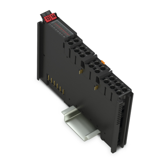
WAGO 750-1515/040-000 Manual (56 pages)
8DO 24VDC 0.5A 2-Wire XTR 8-Channel Digital Output; 24 V DC; 0.5 A; 2-Wire Connection, Extreme For WAGO-I/O-SYSTEM 750 XTR
Brand:
WAGO
| Category:
Control Unit
| Size: 3 MB
Table of Contents
Table of Contents
3
Notes about this Documentation
5
Validity of this Documentation
5
Copyright
5
Symbols
6
Number Notation
7
Font Conventions
7
Table 1: Number Notation
7
Table 2: Font Conventions
7
Important Notes
8
Legal Bases
8
Subject to Changes
8
Personnel Qualifications
8
Use of the 750 Series in Compliance with Underlying Provisions
8
Technical Condition of Specified Devices
9
Disposal
9
2.1.4.1.1 Electrical and Electronic Equipment
9
2.1.4.1.2 Packaging
10
Safety Advice (Precautions)
11
Device Description
14
View
16
Figure 1: View
16
Table 3: Legend for Figure "View
16
Connectors
17
Data Contacts/Local Bus
17
Figure 2: Data Contacts
17
Power Jumper Contacts/Field Supply
18
Figure 3: Power Jumper Contacts
18
Table 4: Legend for Figure "Power Jumper Contacts
18
Push-In CAGE CLAMP ® Connectors
19
Figure 4: Push-In CAGE CLAMP ® Connectors
19
Table 5: Legend for Figure "Push-In CAGE CLAMP ® Connectors
19
Display Elements
20
Operating Elements
20
Figure 5: Display Elements
20
Table 6: Legend for Figure "Display Elements
20
Schematic Diagram
21
Figure 6: Schematic Diagram
21
Technical Data
22
Device Data
22
Power Supply
22
Communication
22
Table 7: Technical Data - Device
22
Table 8: Technical Data - Power Supply
22
Table 9: Technical Data - Communication
22
Outputs
23
Connection Type
23
Mechanical Conditions
23
Table 10: Technical Data - Outputs
23
Table 11: Technical Data - Field Wiring
23
Table 12: Technical Data - Power Jumper Contacts
23
Table 13: Technical Data - Data Contacts
23
Table 14: Technical Data - Mechanical Conditions
23
Climatic Environmental Conditions
24
Table 15: Technical Data - Climatic Environmental Conditions
24
Approvals
25
Standards and Guidelines
26
Table 16: Standards and Rated Conditions for Explosion Protection
26
Table 17: Climatic and Mechanical Environmental Conditions and
27
Table 18: EMC - Immunity to Interference
28
Table 19: EMC - Emission of Interference
30
Table 20: Standards and Rated Conditions for Rail Applications (en 50155)
31
Process Image
32
Table 21: Output Bits
32
Mounting
33
Mounting Sequence
33
Inserting and Removing Devices
34
Inserting the I/O Module
34
Figure 7: Insert I/O Module (Example)
34
Removing the I/O Module
35
Figure 8: Snap the I/O Module into Place (Example)
35
Figure 9: Removing the I/O Module (Example)
35
Connect Devices
36
Connecting a Conductor to the Push-In CAGE CLAMP
36
Figure 10: Connecting a Conductor to a Push-In CAGE CLAMP
36
Using in Safety Related Applications
37
Important Notes
37
Connection for the I/O Module to Safety Switching Devices or F I/O Modules
39
General Structure of a Potential Group
39
Figure 11: Setting up a Potential Group (Example)
39
Table 22: Supply or Filter Modules for Setting up a Potential Group
39
Examples of Connection
40
Figure 12: Two-Channel Single-Pole Disconnection
40
Figure 13: Two-Channel Double-Pole Disconnection
41
Use in Hazardous Environments
42
Marking Configuration Examples
43
Marking for Europe According to ATEX and Iecex
43
Figure 14: Marking Example According to ATEX and Iecex
43
Figure 15: Text Detail - Marking Example According to ATEX and Iecex
43
Table 23: Description of Marking Example According to ATEX and Iecex
44
Figure 16: Marking Example for Approved Ex I I/O Module According to
45
Figure 17: Text Detail - Marking Example for Approved Ex I I/O Module
45
Table 24: Description of Marking Example for Approved Ex I I/O Module According to ATEX and Iecex
46
Table 26: Description of Marking Example for Approved Ex I I/O Module
46
Marking for the United States of America (NEC) and Canada (CEC)
47
Figure 18: Marking Example According to NEC
47
Figure 19: Text Detail - Marking Example According to NEC 500
47
Table 25: Description of Marking Example According to NEC 500
47
Figure 20: Text Detail - Marking Example for Approved Ex I I/O Module
48
Figure 21: Text Detail - Marking Example for Approved Ex I I/O Module
48
Table 27: Description of Marking Example for Approved Ex I I/O Modules
48
Figure 22: Text Detail - Marking Example for Approved Ex I I/O Modules
49
Table 28: Description of Marking Example for Approved Ex I I/O Modules
49
Installation Regulations
50
Special Notes Regarding Explosion Protection
50
Special Notes Regarding ANSI/ISA Ex
52
List of Figures
53
List of Tables
54
Advertisement
Advertisement
Related Products
WAGO 750-1504
WAGO 750-1606/040-000
WAGO 750-1605/040-000
WAGO 750-1405/040-000
WAGO 750-1416/040-000
WAGO 750-1415/040-000
WAGO 750-633
WAGO 750-439
WAGO 750-451/025-000
WAGO 750-616/040-000
WAGO Categories
I/O Systems
Control Unit
Power Supply
Switch
Controller
More WAGO Manuals
Login
Sign In
OR
Sign in with Facebook
Sign in with Google
Upload manual
Upload from disk
Upload from URL