Sign In
Upload
Manuals
Brands
Spectrum Controls Manuals
I/O Systems
SLC 500
Spectrum Controls SLC 500 Manuals
Manuals and User Guides for Spectrum Controls SLC 500. We have
3
Spectrum Controls SLC 500 manuals available for free PDF download: User Manual
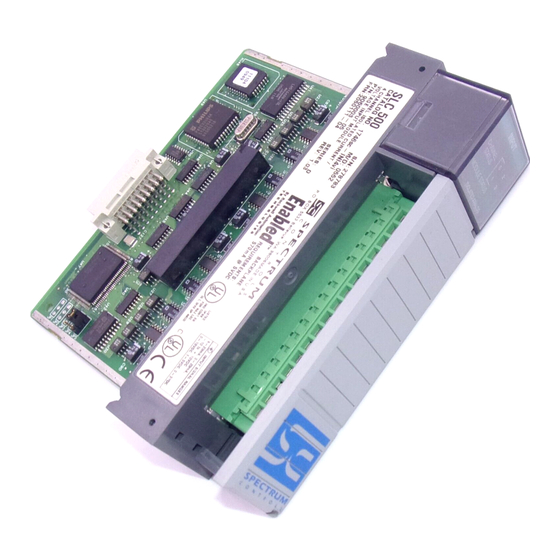
Spectrum Controls SLC 500 User Manual (66 pages)
Counter/Flowmeter Input Module
Brand:
Spectrum Controls
| Category:
I/O Systems
| Size: 2 MB
Table of Contents
Important Notes
2
Table of Contents
3
Module Overview
9
Section 1.1 General Features and Benefits
9
Section 1.2 Increased Accuracy and Reliability
10
Section 1.3 Reduced System Costs
10
Section 1.4 State- Of-The-Art Performance
10
Section 1.5 Detailed Specifications
11
Section 1.6 Regulatory Requirements
13
Diagnostic Leds
13
Section 1.7 System Overview
13
Section 1.8 System Operation
13
Section 1.9 Module Operation
14
Installation and Wiring
15
Section 2.1 Prevent Electrostatic Discharge
16
Emc Directive
16
Section 2.3 Power Requirements
16
Section 2.4 Selecting a Rack Slot
17
Section 2.5 Selecting a Location
17
Section 2.6 Inserting Your Module into the Rack
17
Section 2.7 Wiring Your Module
19
Section 2.8 Preparing and Wiring Cables
21
Block
23
Configuring the 1746Sc-Ctr4/Ctr8
25
Section 3.1 Module ID Code
25
Section 3.2 Module Addressing
25
Section 3.3 Operating Modes
27
Section 3.4 Input Configurations
27
Section 3.5 Modes
29
Section 3.6 Channel Turn-On, Turn-Off, and Reconfiguration Times
30
Section 3.7 Response to Slot Disabling
30
Channel Configuration, Data, and Status
31
Section 4.1 Configuring each Input Channel
31
Section 4.2 Output Register - Scale and Limit Data Values
38
Section 4.3 Input Registers - Channel Data
40
Programming Examples
45
Section 5.1 Simple Linear Counter (10,000 Limit )
45
Section 5.2 Ring Counter Sample
46
Section 5.3 Simple Ring Counter with Flats (20 K Limit )
46
Section 5.4 Using Preset Values with Extended Mode
47
Section 5.5 Using Scaling with Count and Rate Outputs
48
Section 5.6 Application Meter Proving
48
Application
48
Testing Your Module
51
Inspecting Your Module
51
Disconnecting Prime Movers
51
Powering up
52
Interpreting the Led Indicators
52
Codes
53
No Signal
54
Troubleshooting
54
Chapter 7 Maintaining Your Module and Ensuring Safety
57
Section 7.1 Preventive Maintenance
57
Section 7.2 Safety Considerations
57
Section 7.3 Getting Technical Assistance
58
Section 7.4 Declaration of Conformity
59
Appendix A Floating Point Rate Mode
61
Overview
61
Configuring each Input Channel for Floating Point Rate
61
Input Registers: Channel Data
62
Setting the Rate Limit/R Factor
62
Ladder Logic
63
Advertisement
Spectrum Controls SLC 500 User Manual (56 pages)
Brand:
Spectrum Controls
| Category:
Control Unit
| Size: 4 MB
Table of Contents
Important Notes
2
Table of Contents
3
Chapter 1 Module Overview
9
Section 1.1 General Features and Benefits
9
Section 1.2 Detailed Specifications
10
Section 1.3 Regulatory Requirements
13
Chapter 2 Installation and Wiring
15
Section 2.1 Prevent Electrostatic Discharge
16
Section 2.2 Compliance to European Directive
16
Emc Directive
16
Section 2.4 Low Voltage Directive
16
Power Requirements
17
Section 2.5 Selecting a Rack Slot
17
Section 2.6 Selecting a Location
17
Section 2.7 Inserting Your Module into the Rack
18
Section 2.8 Wiring Your Module
19
Chapter 3 Configuring the 1746Sc-Ini4I
23
Section 3.1 How the Processor Communicates with Your Module
23
Output Image-Configuration & User-Defined Scale Limits
24
Input Image-Data and Status Words
24
Section 3.2 the Difference between Channel Update Time and Step Response Time
24
Section 3.3 Selecting a N Input Filter Frequency
25
Section 3.4 Auto-Calibration Time
28
Section 3.5 Channel Enable and Disable Times
29
Section 3.6 Your Module ' S Response T O Slot Disabling
29
Chapter 4 Using Your Input Module
31
Section 4.1 Entering Your Module ID Code
31
Section 4.2 Configuring each Input Channel
31
Input Channel Enable (Configuration Bit 0)
33
Input Range (Configuration Bits 1-3)
34
Data Format (Configuration Bits 4-6)
34
Open Input Circuit Response (Configuration Bits 7 and 8)
35
Input Filter Frequency (Configuration Bits 9 and 10)
35
Auto-Calibration Enable (Configuration Bit 11)
36
Unused Bits (Configuration Bits 12-15)
36
Limits ( Optional )
36
Section 4.4 Monitoring each Input Channel
38
S Configuration and Status
38
Over-Range Error (Status Bit 12)
40
Under-Range Error (Status Bit 13)
40
Non-Fatal Channel Error (Status Bit 14)
40
Fatal Channel Error (Status Bit 15)
40
Chapter 5 Programming Examples
41
Pid Control
41
Section 5.2 User -Defined Scaling
43
Chapter 6 Testing Your Module
45
Section 6.1 Inspecting Your Module
45
Section 6.2 Disconnecting Prime Movers
45
Section 6.4 Interpreting the Led Indicators
46
Section 6.5 Interpreting I/O Error Codes
47
Section 6.6 Troubleshooting
48
Chapter 7 Maintaining Your Module and Ensuring Safety
49
Section 7.1 Preventive Maintenance
49
Section 7.2 Safety Considerations
49
Section 7.3 Getting Technical Assistance
50
Section 7.4 Declaration of Conformity
50
Chapter 8 Verifying Calibration
52
Section 8.3 Verifying Voltage Inputs (Ini4 VI Only )
52
Section 8.4 Service
52
Index
53
Spectrum Controls SLC 500 User Manual (42 pages)
Brand:
Spectrum Controls
| Category:
Control Unit
| Size: 1 MB
Table of Contents
Important Notes
2
Limited Warranty
2
Table of Contents
3
Chapter 1 Module Overview
9
Section 1.1 General Features and Benefits
9
Section 1.2 Detailed Specifications
10
Chapter 2 Installation and Wiring
13
Section 2.1 Prevent Electrostatic Discharge
14
Section 2.2 Power Requirements
15
Section 2.3 Setting the Dip Switch
15
Section 2.4 Selecting a Rack Slot
16
Section 2.5 Selecting a Location
16
Section 2.6 Inserting Your Module into the Rack
17
Section 2.7 Wiring Your Module
18
Chapter 3 Configuring the 1746Sc-Ino4I
21
Section 3.1 Introduction
21
Section 3.2 about Communications
21
Section 3.3 Configuration
22
Channel Update Time
22
Temperature Calibration Time
22
Output Mode Change Time (-Ino4Vi Only)
22
Your Module's Response to Slot Disabling
22
Entering Your Module's ID Code
23
Output Image
24
Input Image
25
Configuring each Output Channel
25
Output Channel Enable (Configuration Bits 0 and 8)
26
Output Range (Configuration Bits 1-3 and 9-11)
26
Data Format (Configuration Bits 4-6 and 12-14)
26
Reset Output or Hold Last Value on Fault (Configuration Bits 7 and 15)
28
Setting the Output Data Limits (or User-Defined Scale)
28
Output Data Limits
29
User-Defined Scale
30
Controlling each Output Channel's Signal
31
Monitoring each Output Channel
32
Checking each Output Channel's Configuration Status
32
Output Data Limiting Enabled (Status Bit 8)
33
Operating Temperature Error (Status Bit 9)
34
Over-Limit Error (Status Bit 10)
34
Under-Limit Error (Status Bit 11)
34
Over-Range Error (Status Bit 12)
34
Under-Range Error (Status Bit 13)
34
Non-Fatal Channel Error (Status Bit 14)
34
Fatal Channel Error (Status Bit 15)
34
Chapter 4 Testing Your Module
35
Section 4.1 Inspecting Your Module
35
Section 4.2 Disconnecting Prime Movers
35
Section 4.4 Interpreting the Led Indicators
36
Advertisement
Advertisement
Related Products
Spectrum Controls 1734
Spectrum Controls 1746sc-CTR4
Spectrum Controls 1769
Spectrum Controls 1769sc-IF4IH
Spectrum Controls 1769sc-IR6I
Spectrum Controls 1769sc-IT6I
Spectrum Controls 1769sc-IT6IK
Spectrum Controls 746sc-CTR8
Spectrum Controls Micro800 2085-IR8-SC
Spectrum Controls Categories
Control Unit
I/O Systems
Monitor
Gateway
More Spectrum Controls Manuals
Login
Sign In
OR
Sign in with Facebook
Sign in with Google
Upload manual
Upload from disk
Upload from URL