Sign In
Upload
Manuals
Brands
Silicon Graphics Manuals
Server
1400
Silicon Graphics 1400 Manuals
Manuals and User Guides for Silicon Graphics 1400. We have
2
Silicon Graphics 1400 manuals available for free PDF download: Maintenance And Upgrade Manual, Quick Start Manual
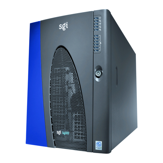
Silicon Graphics 1400 Maintenance And Upgrade Manual (162 pages)
Brand:
Silicon Graphics
| Category:
Server
| Size: 2 MB
Table of Contents
Table of Contents
3
List of Figures
7
About this Guide
13
1 Working Inside the System
15
Tools and Supplies Needed
15
Safety: before You Remove the Access Cover
15
Warnings and Cautions
16
Removing the System Access Cover
17
Installing the Access Cover
17
Figure 1-1 Removing the Access Cover
18
Working in the Subchassis and Electronics Bay
19
Figure 1-2 Opening the Subchassis and Electronics Bay
20
Installing PCI Boards
21
Figure 1-3 Installing a PCI Option Board
22
Removing a PCI Option Board
23
Removing the Front Panel Board
23
Installing the Front Panel Board
24
Figure 1-4 Removing the Front Panel Board
24
Removing the Diskette Drive
25
Figure 1-5 Removing the Diskette Drive from the Chassis
25
Installing the Diskette Drive
26
Peripheral Drives
27
Drive Cabling Considerations
27
IDE Requirements
27
Figure 1-6 IDE Cable Dimensions
27
SCSI Requirements
28
Installing 5.25-Inch Peripherals in the Front Bays
28
Figure 1-7 Removing EMI Shields
30
Figure 1-8 Snap-In Plastic Slide Rails
31
Removing a 5.25-Inch Peripheral from the Front Bay
32
Figure 1-9 Removing a Removable Media Device
33
Installing or Replacing the SCSI-B Cable
34
Figure 1-10 SCSI-B Cable Installation
35
System Fans
36
Removing the System Fan Assembly
36
Figure 1-11 Removing the Fan Assembly
37
Installing the System Fan Assembly
38
Removing an Individual System Fan
38
Figure 1-12 Fan Cabling
39
Installing an Individual System Fan
40
The Power Share Board
41
Replacing the Power Share Board (PSB)
41
Figure 1-13 Chassis Side View
42
Figure 1-14 Removing the Existing Board and Bracket Assembly
43
Figure 1-15 Removing the Existing Board from Its Bracket
44
Figure 1-16 Attaching the New Board to Its Bracket
45
Figure 1-17 Installing the New Board and Bracket Assembly
46
2 Upgrading Baseboard Components
47
Baseboard
47
Removing the Baseboard
47
Installing the Baseboard
49
Figure 2-1 Removing the Baseboard
49
Memory
50
Removing the Memory Module
50
Figure 2-2 Removing the Memory Module
51
Installing the Memory Module
52
Removing Dimms
52
Installing Dimms
53
Processors
54
Figure 2-3 Installing a DIMM
54
Removing a Processor
55
Figure 2-4 Releasing the Retention Module Bracket
56
Figure 2-5 Removing a Processor
57
Installing a Processor
58
Figure 2-6 Installing a Processor
59
Figure 2-7 Installing Tabs on a Processor S.E.C. Cartridge
60
Installing the Processor Tabs
60
Installing Processor Heatsinks
61
Figure 2-8 Installing a Heatsink on a Processor S.E.C. Cartridge
62
Voltage Regulator Modules (Vrms)
63
Table 2-1 VRM and Processor Power Sequence
63
Table 2-2 Processor and VRM Population Sequencing
63
Figure 2-9 Processor and Corresponding VRM Locations
64
Removing a VRM
65
Figure 2-10 Installing a VRM
66
Installing a VRM
66
Replacing the Backup Battery
67
Figure 2-11 Replacing the Lithium Battery
68
3 SGI 1400 Server SCSI Backplane Installation
71
SCSI Backplane Warnings and Cautions
71
Safety: before You Remove the Access Cover
71
General Procedure to Open the Chassis
71
Figure 3-1 Chassis Side View
72
Replacing an Existing Backplane
73
Figure 3-2 Removing the Backplane from the Chassis
74
Figure 3-3 Aligning and Attaching the Backplane
75
Figure 3-4 Reconnecting Cables to the New Backplane
76
General Procedure to Close the Chassis
77
4 Technical Reference
79
Baseboard Connectors
79
Figure 4-1 Baseboard Layout
80
Figure 4-2 Main Power Connector Pins
82
Main Power Connector
82
Table 4-1 Main Power Connector Pinouts
82
Auxiliary Power
83
Figure 4-3 Auxiliary Power Connector
83
Table 4-2 Auxiliary Power Connector Pinouts
83
Diskette Drive
84
Figure 4-4 Diskette Drive Connector
84
Table 4-3 Diskette Drive Connector Pinouts
84
Figure 4-5 Front Panel Connector
86
Front Panel Connector
86
Table 4-4 Front Panel Connector Pinouts
86
Figure 4-6 Server Management Module (SMM) Connector
88
Table 4-5 Server Management Module Connector Pinouts
88
The SMM Connector
88
Figure 4-7 the IPMB Connector
89
Table 4-6 IPMB Connector Pinouts
89
The IPMB Connector
89
Figure 4-8 VGA Video Port Connector
90
Table 4-7 Video Port Connector Pinouts
90
VGA Video Port Connector
90
Keyboard and Mouse
91
Table 4-8 Keyboard and Mouse Connector Pinouts
91
Figure 4-10 Parallel Port Connector
92
Parallel Port
92
Table 4-9 Parallel Port Connector Pinout
92
Serial Ports a and B
93
Table 4-10 Serial Port a (External) Connector Pinout
93
Figure 4-12 USB External Connector
94
Table 4-11 USB External Connector Pinout
94
Table 4-12 USB Internal Header Pinout
94
Universal Serial Bus
94
Figure 4-13 Narrow SCSI Connector
95
Narrow SCSI Connector
95
Table 4-13 Narrow SCSI Connector Pinouts
95
Figure 4-14 Wide SCSI Connector
98
Table 4-14 Wide SCSI Connector Pinouts
98
Wide SCSI Connector
98
Figure 4-15 Internal IDE Connector
100
Internal IDE Connector
100
Table 4-15 IDE Connector Pinouts
100
Figure 4-16 Hard Drive LED Connector
102
Table 4-16 Hard Drive LED Connector Pinouts
102
The Hard Drive LED Connector
102
ISA Connector Pinouts
103
Table 4-17 ISA Connector Pinouts
103
Table 4-18 PCI Connector Pinouts
107
The PCI Connectors
107
Baseboard Jumpers
113
Figure 4-17 Baseboard Jumpers
113
General Procedure to Change a Jumper Setting
114
Table 4-19 Baseboard Jumper Summary
114
CMOS Clear Jumper
115
Password Clear Jumper
115
Recovery Boot Jumper
116
Table 4-20 BIOS Recovery Beep Codes
117
System I/O Addresses
118
Table 4-21 System I/O Addresses
121
Memory Map Address Range
122
Table 4-22 Memory Map Address Range
122
Interrupts
123
Table 4-23 Interrupt I/O Descriptions
123
Video Modes
124
Table 4-24 Standard VGA Modes
124
Table 4-25 Extended VGA Modes
125
Equipment Log and Configuration Worksheets
131
Equipment Log
131
Table A-1 Equipment Log
131
Configuration Worksheets
134
Current Usage
134
Calculating Power Usage
134
Worksheet, Calculating DC Power Usage
135
Table A-2 Power Usage Worksheet
135
Worksheet, Total Combined Power Used by the System
136
Table A-3 Power Usage Worksheet (Total Watts)
136
System Setup Utility (SSU) Worksheets
137
Adding and Removing Boards
137
Table A-4 Add or Remove PCI Boards
137
ISA Board Definition
138
Table A-5 ISA Board Definition
138
Baseboard (SSU, Change Configuration Settings)
139
Table A-6 Systems Group
139
Table A-7 Memory Subsystem Group
139
Table A-8 Onboard Disk Controllers
139
Table A-9 Onboard Communications Devices
140
Table A-10 Diskette Drive Subsystems Group
140
Table A-11 IDE Subsystem Group
140
Table A-12 Multiboot Group
141
Table A-13 Keyboard and Mouse Subsystem Group
141
Table A-14 Console Redirection
141
Table A-15 Security Subsystems Worksheet
142
Table A-16 SCSI ROM BIOS Options Group
142
Table A-17 Management Subsystem Group
142
Management Subsystem, System Sensor Control Worksheet
143
BIOS Setup Worksheets
143
Table A-18 Sensor Control Values
143
Table A-19 Main Menu
143
Table A-20 Primary Master and Slave Submenu
144
Table A-21 Keyboard Features Submenu
144
Table A-22 Advanced Menu
145
Table A-23 PCI Device, Embedded SCSI Submenu
145
Table A-24 PCI Devices Submenu
145
Table A-25 I/O Device Configuration Submenu
146
Table A-26 Advanced Chipset Control Submenu
147
Table A-27 Security Menu
147
Table A-28 Server Menu
148
Table A-29 System Management Submenu
148
Table A-30 Console Redirection Submenu
148
Table A-31 Boot Menu
149
Environmental Specifications
151
Environmental Specifications
151
Chassis Warnings and Safety
153
Power Warnings
153
Cautions When Removing the Chassis Covers
153
Index
157
Advertisement
Silicon Graphics 1400 Quick Start Manual (22 pages)
Brand:
Silicon Graphics
| Category:
Server
| Size: 0 MB
Table of Contents
Quick Start Guide
1
Table of Contents
3
Introducing the SGI 1400 Family of Servers
5
Chassis Configurations
6
Site Selection and Environmental Requirements
7
Using Power Cords
9
Power Cord Requirements
10
Monitor, Keyboard, and Mouse Connectors
10
Turning on the Video Monitor and Server
12
Run the Power-On Self Test
14
Booting from a CD
15
Changing the Boot Device Priority
16
Getting Manuals from the SGI Technical Publications Library
17
Printing Manuals from the CD
17
Using the Acrobat .PDF Files
18
Using the Postscript .PS Files
19
Installing a Postscript Printer with NT
19
Installing a Postscript Printer with Linux
19
Copy Configuration Software to Diskettes
20
Product Warnings
21
Advertisement
Related Products
Silicon Graphics 1450
Silicon Graphics 1200
Silicon Graphics 1400 Series
Silicon Graphics Presenter 1280
Silicon Graphics 1600SW
Silicon Graphics 10-Gigabit Ethernet Network Adapter
Silicon Graphics InfiniteStorage 120
Silicon Graphics 2400
Silicon Graphics 2800
Silicon Graphics Altix XE210
Silicon Graphics Categories
Server
Desktop
Storage
Monitor
Network Hardware
More Silicon Graphics Manuals
Login
Sign In
OR
Sign in with Facebook
Sign in with Google
Upload manual
Upload from disk
Upload from URL