Sign In
Upload
Manuals
Brands
Rockwell Automation Manuals
Controller
SMC Dialog Plus
Rockwell Automation SMC Dialog Plus Manuals
Manuals and User Guides for Rockwell Automation SMC Dialog Plus. We have
1
Rockwell Automation SMC Dialog Plus manual available for free PDF download: User Manual
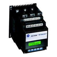
Rockwell Automation SMC Dialog Plus User Manual (189 pages)
Brand:
Rockwell Automation
| Category:
Controller
| Size: 1 MB
Table of Contents
Table of Contents
3
Chapter 1 Product Overview
11
Description
11
Operation
11
Starting Modes
12
Soft Start
12
Selectable Kickstart
13
Current Limit Start
13
Dual Ramp Start
14
Full Voltage Start
14
Energy Saver
15
Phase Rebalance
15
Protection and Diagnostics
15
Overload
15
Figure 1.6 Overload Trip Curves
17
Stall Protection and Jam Detection
18
Open Gate
19
Line Faults
19
Underload
19
Excessive Starts/Hour
20
Overtemperature
20
Metering
20
Communication
21
Programming
21
Status Indication
21
Control Options
22
Soft Stop Option
22
Pump Control Option
23
Preset Slow Speed Option
23
SMB‰ Smart Motor Braking Option
24
Accu-Stop‰ Option
25
Slow Speed with Braking Option
26
Chapter 2 Installation
27
Receiving
27
Unpacking
27
Inspecting
27
Storing
27
General Precautions
28
Heat Dissipation
28
Enclosures
28
Maximum Heat Dissipation
28
Ventilated Enclosures
29
Non-Ventilated Enclosures
29
Mounting
30
Dimensions
30
Figure 2.2 Dimensions: 97 and 135 Amp Controllers
31
Figure 2.3 Dimensions: 180 through 360 Amp Controllers
32
Figure 2.4 Dimensions: 500 Amp Controller
33
Figure 2.5 Dimensions: 650-1000 Amp Controllers
34
Power Factor Correction Capacitors
35
Fast Acting Current-Limiting Fuses
36
Recommended Fuses
36
Protective Modules
37
Motor Overload Protection
37
Bypass
37
Two-Speed Motors
37
Multi-Motor Protection
37
Human Interface Module
38
Connecting the Human Interface Module to the Controller
39
Control Enable
39
Communication Modules
42
Converter Modules
42
Converter Module Selection Guide
42
Figure 2.9 Converter Module Connection Interface
43
Electromagnetic Compatibility (EMC)
44
Enclosure
44
Grounding
44
Wiring
45
Accessory Requirements
45
Chapter 3 Wiring
47
Terminal Locations
47
Figure 3.3 Wiring Terminal Locations (180 to 360 Amp)
48
Power Wiring
49
Tightening Torque
49
Control Power
50
Control Voltage
50
Control Wiring
50
Lug Wire Capacity and Tightening Torque
50
Heatsink Fan Control Power
50
Control Wiring and Tightening Torque
50
Fan Power
51
Fan Terminations
51
Control Terminal Designations
52
Grounding Provision
52
Standard Controller Wiring Diagrams
53
Programmable Control Interfacing
54
Dual Ramp Applications
55
Control Via the Scanport
56
Retrofit Applications
57
Isolation Applications
58
Bypass Applications
59
With Isolation Applications
60
Shunt Trip Applications
61
Speed Reversing Applications
62
Two-Speed Applications
63
Hand-Off-Auto (Scanport) Control
64
Chapter 4 Programming
65
Overview
65
Keypad Description
65
Programming Menu
65
Figure 4.1 Menu Structure Hierarchy
66
Parameter Linear List
68
Table 4.A Parameter Linear List
68
Password
69
Search
69
Parameter Management
70
Random Access Memory (RAM)
70
Read-Only Memory (ROM)
70
Electrically Erasable Programmable Read-Only Memory (EEPROM)
70
Using Parameter Management
71
Parameter Modification
72
Soft Start
73
Current Limit Start
73
Dual Ramp Start
74
Full Voltage Start
74
Basic Setup
75
Advanced Setup
76
Example Settings
77
Undervoltage
77
Overvoltage
77
Jam
77
Underload
77
Chapter 5 Calibration
79
Overview
79
Motor Data Entry
79
Motor Codes
80
Table 5.A Motor Codes
80
Calibration Procedure
81
Chapter 6 Metering
83
Overview
83
Viewing Metering Data
83
Chapter 7 Options
85
Overview
85
Human Interface Module
85
Programming Parameters
87
Control Wiring for Scanport Control
89
Soft Stop, Pump Control, and SMB Smart Motor Braking Options
89
Figure 7.2 Typical Retrofit Wiring Diagram
90
Requiring an Isolation Contactor
91
Requiring a Bypass Contactor
92
Or Programmable Controller Interfacing
93
Hand-Off-Auto (Scanport) Control
94
Soft Stop Option
95
Pump Control Option
96
SMB Smart Motor Braking Option
97
Preset Slow Speed and Accu-Stop Options
98
Requiring an Isolation Contactor
100
Requiring a Bypass Contactor
101
Hand-Off-Auto (Scanport) Control
102
Preset Slow Speed Option
103
Accu-Stop Option
104
Slow Speed with Braking Option
105
Slow Speed with Braking Option
106
Of Operation
109
Chapter 8 Serial Communications
110
Overview
110
Logic Control Data
110
Control Wiring
110
Control Enable
111
SMC Status Data
112
Reference/Feedback
112
Parameter Listing
112
Scale Factor Conversion
112
Display Unit Equivalents
113
Datalinks
113
Interfacing
113
Processing Time
113
Remote I/O Examples
114
Example #1 - SLC 500 Controller Without Block Transfer
114
1203-GD1 Communication Module Switch Settings
115
G File Configuration
116
I/O Addressing
116
Example #1 - Ladder Logic Program
118
Example #2 - SLC 500 Controller with Block Transfer
119
1203-GD1 Communication Module Switch Settings
119
Example #2 - Ladder Logic Program
124
Example #3 - PLC 5/20, 5/40, 5/60, and 5/80
127
1203-GD1 Communication Module Switch Settings
128
I/O Addressing
128
Block Transfer Instructions
130
Block Transfer Datafiles
131
Example #3 Ladder Logic Program
132
Devicenet Examples
133
Example #1 SLC Controller with Explicit Messaging
133
1203-GK5 Communication Module Switch Settings
133
Example Information
134
Switch Settings
134
I/O Mapping
134
SMC Dialog Plus Controller Logic Command Addresses
137
Explicit Messaging
138
Explicit Message Request (Get Attribute Multiple)
138
Explicit Message Response (Get Attribute Multiple)
139
Examples
140
Sequence of Events
140
Setting up the Data File
141
Example Ladder Logic Program
142
Chapter 9 Diagnostics
144
Overview
144
Protection Programming
144
Fault Display
144
Clear Fault
144
Fault Buffer
145
Fault Codes
145
Fault Auxiliary Contact
145
Fault Definitions
146
Power Loss
146
Line Fault
146
Phase Reversal
146
Overvoltage and Undervoltage Protection
146
Voltage Unbalance
147
Stall Protection
147
Jam Detection
147
Overload Protection
147
Underload
147
Open Gate
148
Excess Starts/Hour
148
Controller Temp
148
Comm Fault
148
Chapter 10 Troubleshooting
150
Introduction
150
Control Module Removal
155
Control Module Replacement
185
Protective Cover Removal
187
Advertisement
Advertisement
Related Products
Rockwell Automation SMC FLEX
Rockwell Automation Reliance SP500
Rockwell Automation Samsung NX-SCU
Rockwell Automation Allen-Bradley SMC-50
Rockwell Automation SMC-Flex
Rockwell Automation GUARDSHIELD SAFE 4
Rockwell Automation GuardShield Safe 4 PAC
Rockwell Automation Allen-Bradley SLC 500 BASIC
Rockwell Automation POINT Series
Rockwell Automation SD3100
Rockwell Automation Categories
Controller
Control Unit
Power Supply
DC Drives
Industrial Equipment
More Rockwell Automation Manuals
Login
Sign In
OR
Sign in with Facebook
Sign in with Google
Upload manual
Upload from disk
Upload from URL