Sign In
Upload
Manuals
Brands
REMEHA Manuals
Boiler
Gas 120 ACE - 65
REMEHA Gas 120 ACE - 65 Manuals
Manuals and User Guides for REMEHA Gas 120 ACE - 65. We have
2
REMEHA Gas 120 ACE - 65 manuals available for free PDF download: User Manual, Installation And Service Manual
REMEHA Gas 120 ACE - 65 User Manual (96 pages)
MID control box equipped with a HMI T-control
Brand:
REMEHA
| Category:
Boiler
| Size: 5.61 MB
Table of Contents
Table of Contents
3
1 Safety
6
General Safety Instructions
6
Safety Instructions for the Installer
6
Safety Instructions for the User
7
Recommendations
8
Liabilities
9
Manufacturer's Liability
9
Installer's Liability
9
User's Liability
9
2 About this Manual
11
Symbols Used
11
Symbols Used in the Manual
11
Symbols Used on the Appliance
11
3 Technical Specifications
12
Homologations
12
Standards & Directives
12
Factory Test
12
Electrical Diagram
13
Electrical Diagram for the MID Control Unit HMI T-Control
13
4 Description of the Product
14
General Description
14
Main Components
14
Pcbs
14
SCB-02 Expansion Board Description
14
Description of the CB-09 PCB
15
Description of the IF-01 PCB
15
Control Panel Description
16
Description of the User Interface
16
Description of the Main Screen
16
Standard Delivery
17
Accessories & Options
17
5 Installation
18
Installation Regulations
18
Unpack and Fit the Control Box
18
Electrical Connections
21
Recommendations
21
Electrical Power Supply
21
Recommended Cable Cross Section
21
Cable Routing and Access to the Connection Terminal Blocks
22
Connecting a Modulating Thermostat
23
Connecting an On/Off Thermostat
23
Frost Protection Combined with On/Off Thermostat
24
Frost Protection Combined with Outdoor Temperature Sensor
24
Connecting an Outdoor Temperature Sensor
24
Blocking Input
24
Release Input
25
Connecting External Sensors
25
Connecting a Tank Sensor or Thermostat
25
Connecting a PWM Pump
26
Connecting a Standard Pump
26
Connecting a Domestic Hot Water (DHW) Pump
26
Connecting a Three-Way Valve
27
Connecting a System Pump for MIX Group
27
Connecting Status Notifications
27
Connecting 0-10 V Output
27
Connection Options for the Expansion PCB - IF-01
28
Connecting a Pc/Laptop
29
6 Connecting Diagrams and Configuration
30
Factory Settings for Circuits
30
Connection Example - SCB-02
30
7 Commissioning
32
General
32
Check-List before Commissioning
32
Checking the Gas Inlet
32
Setting the Pressure in the Gas Circuit
33
Checking the Electrical Connections
33
Checking the Hydraulic Circuit
33
Starting and Stopping the Boiler
34
Commissioning
34
Shutting down the Boiler
34
Gas Settings
34
Adapting/Adjusting the Boiler to Different Types of Gas
34
Checking/Adjusting the Combustion
36
Displaying the Water Pressure on the Control Panel
38
Modifying the ΔT Value
38
Points to Check after Commissioning
39
8 Operation
40
Definition of Zone and Activity
40
Zone
40
Activity
40
Switching the Summer Mode on or off
40
Activating the Holiday Program
40
Changing the Basic Settings
41
Changing the Name of an Activity
41
Personalising the Name and Symbol for a Zone
41
Room Temperature for a Zone
42
Selecting the Operating Mode
42
Changing the Temperature Settings of a Zone
42
Changing the Room Temperature Temporarily
42
Timer Programming for Heating
42
Domestic Hot Water Temperature
43
Selecting the Operating Mode
43
Forcing Domestic Hot Water Production (Override)
43
Modifying the Domestic Hot Water Set Point Temperatures
44
Timer Programming for Domestic Hot Water
44
9 Settings
45
Accessing the Installer Level
45
Setting the Heating Curve
45
Drying Screed
45
Configuring the Maintenance Message
46
Saving the Installer Details
46
Saving the Commissioning Settings
46
Resetting or Re-Establishing the Parameters
47
Resetting after Replacing the PCB
47
Auto-Detecting Options and Accessories
47
Reverting to the Commissioning Settings
47
Reverting to the Factory Settings
47
Accessing Information on the Hardware and Software Versions
47
Menu Tree
48
List of Parameters
48
Introduction to Parameter Codes
48
Changing the Parameters
48
Control Unit Settings
49
List of Parametersscb-02
52
Reading out Measured Values
60
Control Unit Counters
60
SCB-02 Counters
61
Control Unit Signals
62
SCB-02 Signals
68
10 Maintenance
76
General
76
Maintenance Message
76
Viewing the Service Notifications
76
Standard Inspection and Maintenance Operations
77
Checking the Combustion
77
Venting the Heating System
77
Draining the Heating System
78
Check the Hydraulic Pressure
78
Topping up the Installation with Water
78
Cleaning the Casing
79
Specific Maintenance Operations
79
Carrying out an Auto-Detect
79
Other Specific Maintenance Operations
79
11 Troubleshooting
80
Displaying and Clearing the Error Memory
80
Error Codes
80
Warning
80
Blockage
81
Lock out Codes CU-GH-08
83
12 Decommissioning
86
Decommissioning Procedure
86
Recommissioning Procedure
86
13 Disposal and Recycling
87
14 Environmental
88
Energy Savings
88
Room Thermostat and Settings
88
15 Warranty
89
General
89
Terms of Warranty
89
16 Spare Parts
90
General
90
Spare Parts Lists
90
Control Panel
90
17 Appendix
92
Package Fiche - Boilers
92
Product Fiche - Temperature Controls
93
Product Fiche
93
Advertisement
REMEHA Gas 120 ACE - 65 Installation And Service Manual (60 pages)
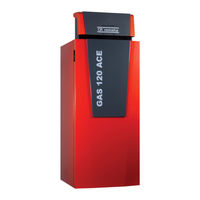
Floor-standing condensing gas boiler
Brand:
REMEHA
| Category:
Boiler
| Size: 4.97 MB
Table of Contents
Table of Contents
3
1 Safety
5
General Safety Instructions
5
Recommendations
7
Liabilities
8
Manufacturer's Liability
8
Installer's Liability
9
User's Liability
9
2 Symbols Used
10
Symbols Used in the Manual
10
Symbols Used on the Appliance
10
3 Technical Specifications
11
Homologations
11
Directives
11
EC Declaration of Conformity
11
Gas Categories
11
Certifications
11
Factory Test
12
Technical Data
12
Erp Technical Parameters
14
Circulating Pump (Not Provided)
14
Sensor Specifications
15
Dimensions and Connections
16
Electrical Diagram
17
Electrical Diagram of Boiler
17
4 Description of the Product
19
General Description
19
Operating Principle
19
Gas/Air Setting
19
Settings and Safety Devices
19
Main Boiler Components
20
Pcbs
20
Description of the CU-GH-08 PCB
20
Standard Delivery
20
Accessories & Options
20
5 Installation
21
Installation Regulations
21
Choice of the Location
21
Data Plate
21
Space Required - Boiler Ventilation
21
Ventilation
22
Fitting the Outdoor Sensor
23
Transport
24
Unpacking and Preparing the Boiler
24
Hydraulic Connections
27
Water Treatment
27
Flushing New Installations and Installations Less than 6 Months Old
28
Flushing an Existing Installation
28
Connecting the Heating Circuit
28
Connecting the Condensate Discharge Pipe
28
Filling the Siphon
29
Gas Connection
29
Gas Supply
30
Air Supply/Flue Gas Outlet Connections
30
Classification
30
Lengths of the Air/Flue Gas Pipes
33
Dimensions of Flue Gas Outlet Pipe
34
Connection to the Flue Gas Pipe
35
6 Operation
37
Settings
37
7 Maintenance
38
General
38
Specific Maintenance Operations
38
Cleaning the Siphon
38
Checking the Ionisation Current
39
Replace the Ionization/Ignition Electrode
40
Servicing the Forced Flue Connection Pipes
40
Checking the Burner and Cleaning the Heat Exchanger
40
Checking the Non-Return Valve
42
8 Decommissioning
43
Decommissioning Procedure
43
Recommissioning Procedure
43
9 Disposal and Recycling
44
10 Environmental
45
Energy Savings
45
Room Thermostat and Settings
45
11 Warranty
46
General
46
Terms of Warranty
46
12 Spare Parts
47
General
47
Spare Parts Lists
47
Exchanger
47
Gas Circuit
48
Hydraulic Circuit
50
Boiler Body
51
Casing
52
Boiler PCB Housing
53
13 Appendix
54
Package Fiche - Boilers
54
Product Fiche - Temperature Controls
55
Product Fiche
55
Advertisement
Related Products
REMEHA Gas 120 ACE - 90
REMEHA Gas 120 ACE - 115
Remeha 18s
REMEHA Avanta 18v
REMEHA Avanta 12v
REMEHA Gas 110 Eco 65
REMEHA Avanta 15v
Remeha Gas 110 Eco 115
REMEHA Gas 210 ECO
REMEHA Gas 310 ECO
REMEHA Categories
Boiler
Thermostat
Controller
Boiler Supplies
Water Heater
More REMEHA Manuals
Login
Sign In
OR
Sign in with Facebook
Sign in with Google
Upload manual
Upload from disk
Upload from URL