Table of Contents
Advertisement
Advertisement
Table of Contents

Related Manuals for REMEHA GAS 120 ACE Series


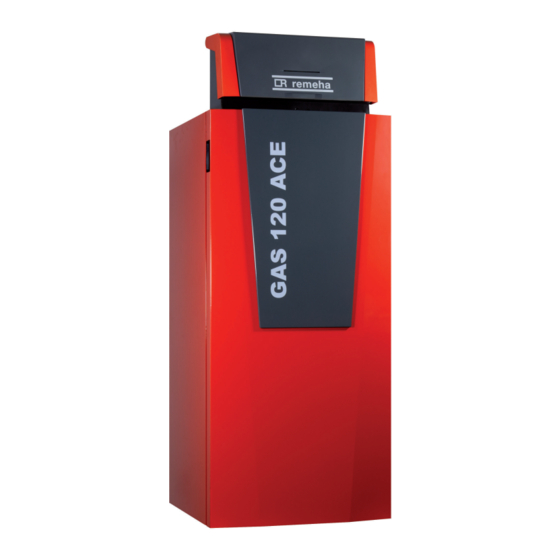
Summary of Contents for REMEHA GAS 120 ACE Series
- Page 1 MID control box equipped with a HMI T-control for Gas 120 ACE boiler...
- Page 2 Dear Customer, Thank you very much for buying this appliance. Please read through the manual carefully before using the product, and keep it in a safe place for later reference. In order to ensure continued safe and efficient operation we recommend that the product is serviced regularly. Our service and customer service organisation can assist with this.
-
Page 3: Table Of Contents
Contents Contents Safety ................... . 6 General safety instructions . - Page 4 Contents Connection example - SCB-02 ..............30 Commissioning .
- Page 5 Contents 10.2 Maintenance message ............... . . 76 10.2.1 Viewing the service notifications .
-
Page 6: Safety
1 Safety Safety General safety instructions Danger This appliance can be used by children aged from 8 years and above and persons with reduced physical, sensory or mental capabilities or lack of experience and knowledge if they have been given supervision or instruction concerning use of the appliance in a safe way and understand the hazards involved. -
Page 7: Safety Instructions For The User
1 Safety Warning The condensation drain must not be changed or sealed. If a condensate neutralisation system is used, the system must be cleaned regularly in accordance with the instructions provided by the manufacturer. Caution Do not touch the flue gas pipes. Depending on the boiler settings, the temperature of the flue gas pipes can rise to over 60°C. -
Page 8: Recommendations
1 Safety Caution Do not touch radiators for long periods. Depending on the boiler settings, the temperature of the radiators may exceed 60°C. Caution Take precautions with the domestic hot water. Depending on the boiler settings, the domestic hot water temperature may exceed 65°C. Recommendations Danger For safety reasons, we recommend fitting smoke and CO... -
Page 9: Liabilities
1 Safety Caution The appliance should be switched to Summer or Frost Protection mode rather than be switched off in order to guarantee the following functions: Avoidance of pumps blocking Frost Protection Important Respect the minimum and maximum water inlet pressure to ensure correct operation of the boiler: refer to the chapter Technical Specifications. - Page 10 1 Safety Call on a qualified professional to carry out installation and initial commissioning. Get your installer to explain your installation to you. Have the required inspections and maintenance carried out by a qualified installer. Keep the instruction manuals in good condition close to the appliance. MID _HMI T-control - Gas 120 ACE 7717201 - v03 - 25062019...
-
Page 11: About This Manual
2 About this manual About this manual Symbols used 2.1.1 Symbols used in the manual This manual uses various danger levels to draw attention to special instructions. We do this to improve user safety, to prevent problems and to guarantee correct operation of the appliance. Danger Risk of dangerous situations that may result in serious personal injury. -
Page 12: Technical Specifications
3 Technical specifications Technical specifications Homologations 3.1.1 Standards & Directives This product complies with the requirements of the following European directives and standards: Standards: EN15502 Efficiency Directive 92/42/EC Low Voltage Directive 2014/35/EU Generic standard: EN 60335-1 Relevant standard: EN 60335-2-102 Electromagnetic Compatibility Directive 2014/30/EU Generic standards: EN 61000-6-3, EN 61000-6-1 Relevant Standard: EN 55014... -
Page 13: Electrical Diagram
3 Technical specifications Electrical diagram 3.2.1 Electrical diagram for the MID control unit HMI T-control Fig.2 10 A 230V/50Hz CB-09 IF-01 SCB-02 230V 12 11 MW-2000917-01 1 MID control panel HMI T-control BL Blue 2 Service connector, allows the technician to work on BR Brown the equipment G/Y Green/Yellow... -
Page 14: Description Of The Product
4 Description of the product Description of the product General description The control box is used to control the operation of a Gas 120 ACE boiler. The box is equipped with a HMI T-control control panel. Main components Fig.3 1 Protective cover 2 On/Off switch 3 HMI T-control control panel 4 Service connector, allows the technician to work on the equipment... -
Page 15: Description Of The Cb-09 Pcb
4 Description of the product Important If the boiler is fitted with the SCB-02 board, then this is automatically recognised by the automatic control unit of the boiler. On removing this board, the boiler will show an error code. To prevent this error, carry out an auto-detect immediately after removing this board. -
Page 16: Control Panel Description
4 Description of the product Caution Do not connect a frost thermostat or room thermostat to the boiler if using the 0–10 V PCB. Control panel description 4.4.1 Description of the user interface Fig.7 1 Rotary knob to select a menu or setting 2 Validation button 3 Back key to return to the previous level or previous menu... -
Page 17: Standard Delivery
4 Description of the product Standard delivery The package contains: A complete control box for a Gas 120 ACE boiler Two mounting bolts with two serrated washers An outdoor temperature sensor A control box installation, user and service manual Accessories & options A detailed list of accessories and options can be found in our catalogue. -
Page 18: Installation
5 Installation Installation Installation regulations Caution The appliance must be installed and maintained by a certified professional in accordance with prevailing statutory texts and codes of practice. Unpack and fit the control box Caution Wear gloves when handling the control box. Fig.9 1. - Page 19 5 Installation Fig.11 5. Remove the front door. MW-2000680-03 Fig.12 6. Remove the two retaining screws from the front top panel. MW-6000762-01 Fig.13 7. Open the control box cover. 90º MW-6000763-02 Fig.14 8. Align the boiler's tapered interlocks with the notches on the control box.
- Page 20 5 Installation Fig.15 9. Fit the box and slide it forwards. 10. Lock the box using the two screws and toothed washers supplied in the bag with the manual. MW-6000765-02 Fig.16 11. Tilt the assembly backwards. 12. Connect the two connectors from the boiler to the connectors on the control box.
-
Page 21: Electrical Connections
5 Installation Electrical connections 5.3.1 Recommendations Only qualified professionals may carry out electrical connections, always with the power off. Earth the appliance before making any electrical connections. Power the appliance via a circuit that includes an omni-polar switch with contact opening distance of 3 mm or more. When making electrical connections to the mains, respect the polarities. -
Page 22: Cable Routing And Access To The Connection Terminal Blocks
5 Installation Caution Provide a separate power supply for the pump and a power switch, if necessary. The output available per outlet is 450 W (2 A, with cos ϕ = 0.7) and the inrush current must be less that 16 A. If the load exceeds either of these values, the control must be relayed using a contactor that must in no circumstances be installed in the control panel. -
Page 23: Connecting A Modulating Thermostat
5 Installation 5. Ensure that the cables are correctly routed and affix the cable(s) using the traction arrester devices. Fig.23 230 V 230 V circuits (left) Sensor Sensor circuits (right) Danger Separate the sensor cables from the 230 V circuit cables. 6. -
Page 24: Frost Protection Combined With On/Off Thermostat
R-Bus terminals of the connector. Warning If a Remeha eTwist or OpenTherm thermostat is used, a frost thermostat cannot be connected in parallel to the R-Bus terminals. In this case, ensure frost protection of the central heating system MW-2000921-01 in combination with an outside sensor. -
Page 25: Release Input
5 Installation 5.3.11 Release input Fig.30 to CB-09 The boiler has a release input (normally open contact). This input relates to the RL terminals of the connection terminal block. If this contact is closed when there is a heat demand, the boiler will be blocked after a waiting time. -
Page 26: Connecting A Pwm Pump
5 Installation 5.3.14 Connecting a PWM pump Fig.33 to CB-09 1. Connect the modulating pump to the X4 terminal for the power section and to the PWM terminal for the control section, respecting the pump polarity. CB-09 Tout - MW-2000878-02 5.3.15 Connecting a standard pump Fig.34... -
Page 27: Connecting A Three-Way Valve
5 Installation Fig.35 DHW pump connector Connect the pump as follows: Earth N Neutral L Phase AD-4000123-01 5.3.17 Connecting a three-way valve Connecting a three-way valve (230 VAC). The connection can be used for a boiler group (zone). Fig.36 Three-way valve connector Connect the three-way valve as follows: Earth N Neutral... -
Page 28: Connection Options For The Expansion Pcb - If-01
5 Installation Caution If possible, use the pump modulation signal. This provides the most accurate pump control. If the automatic burner unit does not support pump modulation, the pump will behave as an on/off pump. 5.3.21 Connection options for the expansion PCB - IF-01 Fig.40 IF-01 PCB The expansion board IF-01 is pre-installed in the instrument box as... -
Page 29: Connecting A Pc/Laptop
5 Installation The 0–10 V signal controls the boiler output. This control modulates on the basis of the heat output. The minimum output is linked to the boiler's modulation depth. The output varies between the minimum and maximum value on the basis of the value defined by the controller. Analogue output (0–10 V) Fig.42 Switch jumper (1) -
Page 30: Connecting Diagrams And Configuration
6 Connecting diagrams and configuration Connecting diagrams and configuration Factory settings for circuits In the factory, the different circuits are configured as indicated in the table. You can modify this configuration and adapt it to the needs of your installation using the installation type described here as a guide. Tab.7 Circuit Circuit type... - Page 31 6 Connecting diagrams and configuration Important All the factory settings of the SCB-02 are adequate for this connection. 7717201 - v03 - 25062019 MID _HMI T-control - Gas 120 ACE...
-
Page 32: Commissioning
7 Commissioning Commissioning General Commissioning the boiler is done for first time use, after a prolonged shut- down (more than 28 days) or after any event that would require complete re-installation of the boiler. Commissioning of the boiler allows the user to review the various settings and checks to be made to start up the boiler in complete safety. -
Page 33: Setting The Pressure In The Gas Circuit
7 Commissioning 7.3.1 Setting the pressure in the gas circuit Fig.45 1 Gas valve - Gas 120 ACE - 65 Gas 120 ACE - 90 2 Gas valve - Gas 120 ACE - 115 Warning Ensure that the boiler is switched off. Do not commission the boiler if the type of gas supplied does not match the gas types approved for the boiler. -
Page 34: Starting And Stopping The Boiler
7 Commissioning Starting and stopping the boiler 7.6.1 Commissioning Caution Initial commissioning must be done by a qualified professional. If adapting to another type of gas, e.g. propane, the boiler must be adjusted before it is switched on. 1. Open the main gas valve. 2. - Page 35 7 Commissioning Tab.9 If operating on propane Type of boiler Action Gas 120 ACE - 65 Rotate the setting screw A on the venturi 6½ turns in a clockwise direction Gas 120 ACE - 90 Rotate the setting screw A on the venturi 6½ turns in a clockwise direction Replace the current gas valve unit with the propane gas valve unit according to the instruc...
-
Page 36: Checking/Adjusting The Combustion
7 Commissioning 7.7.2 Checking/adjusting the combustion Fig.47 1. Unscrew the cap from the flue gas measuring point. 2. Insert the probe for the flue gas analyser into the measurement opening. Important During measurement, seal the opening around the sensor fully. The flue gas analyser must have a minimum accuracy of ±0.25% O 3. - Page 37 7 Commissioning Tab.15 Values at full load for G30/G31 (butane/propane) (1)(2) Gas 120 ACE - 65 4.9 - 5.4 10.2 - 10.5 Gas 120 ACE - 90 4.9 - 5.4 10.2 - 10.5 Gas 120 ACE - 115 4.9 - 5.4 10.2 - 10.5 (1) nominal value...
-
Page 38: Displaying The Water Pressure On The Control Panel
7 Commissioning Tab.17 Values at part load for G31 (propane) (1)(2) Gas 120 ACE - 65 - 5.7 10.0 - 10.2 Gas 120 ACE - 90 - 5.8 9.9 - 10.1 Gas 120 ACE - 115 - 6.3 9.6 - 9.9 (1) nominal value (2) Values given as a guide Tab.18... -
Page 39: Points To Check After Commissioning
7 Commissioning Tab.19 Standard ΔT values Boiler model Standard ΔT Max. ΔT Gas 120 ACE - 65 25 K 40 K Gas 120 ACE - 90 25 K 40 K Gas 120 ACE - 115 20 K 35 K Increase the ΔT value using the GP021 parameter. When increasing the ΔT, the control unit limits the linear flow temperature to 80 °C maximum. -
Page 40: Operation
8 Operation Operation Definition of zone and activity 8.1.1 Zone Fig.52 Term given to the different hydraulic circuits CIRCA, CIRCB, ..It indicates several rooms served by the same circuit. Tab.20 Example Marker Zone Factory-set name Zone 1 CIRCA Zone 2 CIRCB MW-1001145-2 8.1.2... -
Page 41: Changing The Basic Settings
8 Operation 1. Select the Holiday Mode icon. 2. Set the following parameters: Tab.22 Parameter Description Start date holiday Set the date and time for the start of the absence period. End date holiday Set the date and time for the end of the absence period. Wished room temperature during holiday Set the desired room temperature for the absence period Reset... -
Page 42: Room Temperature For A Zone
8 Operation 4. Modify the name of the zone (20 characters max.). 5. Select Icon display zone. 6. Modify the linked symbol. Tab.25 Factory-set name and symbol Customer-set name and symbol CIRCB Room temperature for a zone 8.7.1 Selecting the operating mode To set the room temperature for the different living zones, you can choose between five operating modes: 1. -
Page 43: Domestic Hot Water Temperature
8 Operation Creating a timer programme for heating A timer programme can be used to vary the room temperature in a living zone depending on activities during the day. This can be programmed for each day of the week. 1. Select the icon for the zone to be programmed, , for example. -
Page 44: Modifying The Domestic Hot Water Set Point Temperatures
8 Operation 8.8.3 Modifying the domestic hot water set point temperatures You can modify the "Comfort domestic hot water" and "Reduced domestic hot water" set point temperatures. 1. Select the icon for the DHW zone. 2. Select one of the following menus: Menu Description ComfortZoneDHWtemp... -
Page 45: Settings
9 Settings Settings Accessing the Installer level Certain parameters, which may affect the operation of the appliance, are protected by an access code. Only the installer is authorised to modify these parameters. To access the installer level: 1. Select the icon. -
Page 46: Configuring The Maintenance Message
9 Settings Fig.57 3. Set the following parameters: ° C Parameters Description Zone screed drying Number of days of drying (1) ScreedStartTemp Drying start temperature (2) ScreedStopTemp Drying end temperature (3) The screed drying programme will start immediately and continue for the 00:00 00:00 00:00... -
Page 47: Resetting Or Re-Establishing The Parameters
9 Settings When you have saved the commissioning settings, the option Revert commissioning settings is available in the Advanced Service Menu. Resetting or re-establishing the parameters. 9.7.1 Resetting after replacing the PCB Configuration numbers must be reset if the boiler or burner safety unit PCB is replaced. -
Page 48: Menu Tree
9 Settings Component Description SCB-02 Information about the PCB controlling the zones for heating and domestic hot water CB-09 Information on the input/output control PCB Menu tree Level 1 menus accessible with the button: Level 1 menu Installation Setup Commissioning Menu Advanced Service Menu Error History System Settings... -
Page 49: Control Unit Settings
9 Settings Caution Changing the factory settings may adversely affect the operation of the boiler. 9.10.3 Control unit settings Important All tables show the factory setting for the parameters. The tables also list parameters that are only applicable if the boiler is combined with other equipment such as an outdoor sensor. - Page 50 9 Settings Tab.33 Factory settings at INSTALLER level Code Display text Description Range Gas 120 Gas 120 Gas 120 ACE - 65 ACE - 90 ACE - 115 AP001 BL input setting Blocking input setting (1: Full 1 = Full blocking blocking, 2: Partial blocking, 3: 2 = Partial blocking User reset locking)
- Page 51 9 Settings Code Display text Description Range Gas 120 Gas 120 Gas 120 ACE - 65 ACE - 90 ACE - 115 AP108 OutsideSensorEn Enable the function Outside 0 = Auto abled Sensor 1 = Wired sensor 2 = Wireless sensor 3 = Internet measured 4 = None CP000...
-
Page 52: List Of Parametersscb-02
9 Settings Code Display text Description Range Gas 120 Gas 120 Gas 120 ACE - 65 ACE - 90 ACE - 115 GP022 Tfa Filter Tau Tau factor for average flow 1 - 255 temperature calculation PP014 ChPumpDTRedu Reduction of temperature delta 0 °C - 40 °C ction modulating for pump... - Page 53 9 Settings Factory Parameter Text display Description setting CP021 Zone Function Functionality of the zone Adjustment range: 0 =Disable 1 =Direct 2 =Mixing Circuit 3 =Swimming pool 4 =High Temperature 5 =Fan Convector 6 =DHW tank 7 =Electrical DHW 8 =Time Program 9 =ProcessHeat 10 =DHW Layered 11 =DHW Internal tank...
- Page 54 9 Settings Factory Parameter Text display Description setting CP086 User T.Room Activity Room setpoint temperature of the user zone activity Adjustment range: from 5 °C to 30 °C CP087 User T.Room Activity Room setpoint temperature of the user zone activity Adjustment range: from 5 °C to 30 °C CP088...
- Page 55 9 Settings Factory Parameter Text display Description setting CP251 CalSondeAmbZone Calibration of Zone Room Unit Adjustment range: from -5 °C to 5 °C CP290 ConfigZonePumpOut Configuration of Zone Pump Output Adjustment range: 0 =Zone output 1 =CH mode 2 =DHW mode 3 =Cooling mode 4 =Error report 5 =Burning...
- Page 56 9 Settings Factory Parameter Text display Description setting CP471 Zone screed drying Setting of the screed drying program of the zone Adjustment range: 0 Days =30 Days CP480 ScreedStartTemp Setting of the start temperature of the screed drying program of the zone Adjustment range: from 20 °C to 50 °C CP481...
- Page 57 9 Settings Factory Parameter Text display Description setting CP660 Icon display zone Choice icon to display this zone Adjustment range: 0 =None 1 =All 2 =Bedroom 3 =Livingroom 4 =Study 5 =Outdoor 6 =Kitchen 7 =Basement 8 =Swimming Pool 9 =DHW Tank 10 =DHW Electrical Tank 11 =DHW Layered Tank 12 =Internal Boiler Tank...
- Page 58 9 Settings Factory Parameter Text display Description setting CP741 Zone cool down speed Selection of cool down speed of the zone Adjustment range: 0 =Slowest 1 =Slower 2 =Normal 3 =Faster 4 =Fastest CP750 MaxZone Preheat time Maximum zone preheat time Adjustment range: from 0 Min to 240 Min CP751...
- Page 59 9 Settings Tab.37 Factory Parameter Text display Description setting EP018 Status relay func. Status relay function Adjustment range: 0 =No Action 1 =Alarm 2 =Alarm Inverted 3 =Burning 4 =Not burning 5 =Reserved 6 =Reserved 7 =Service request 8 =Boiler on CH 9 =Boiler on DHW 10 =CH pump on 11 =Locking or Blocking...
-
Page 60: Reading Out Measured Values
9 Settings Parameter Text display Description Factory setting AP074 Force summer mode The heating is stopped. Hot water is maintained. Force Summer Mode Adjustment range: 0 =Off 1 =On AP079 Building Inertia Inertia of the building used for heat up speed Adjustment range: from 0 to 10 AP080... -
Page 61: Scb-02 Counters
9 Settings Tab.42 Counters at installer level Code Display text Description Range Submenu AC001 Hours on mains Number of hours that the 0 Hours - 4294967295 System Functionality appliance has been on mains Hours power AC002 Service Burning Number of hours that the 0 Hours - 131068 Hours Gas fired appliance appliance has been producing... -
Page 62: Control Unit Signals
9 Settings Tab.44 Zone High Temperatur CC001 Zone Pump Run Hours Numbers of pump operating 0 4294967295 hours of the zone CC002 Zone Pump Run Hours Numbers of pump operating 0 4294967295 hours of the zone CC010 Zone Nbr Pump Starts Numbers of times the pump of 0 4294967295 the zone has started... - Page 63 9 Settings Code Display text Description Range Submenu DHW blocking Domestic hot water preparation 0 = No Gas fired appliance active blocking is active 1 = Yes Anti legionella act. Anti legionella is active 0 = Off Internal DHW 1 = On Tank DHW Gas fired appliance DHW active...
- Page 64 9 Settings Code Display text Description Range Submenu AM016 System Flow Flow temperature of appliance. -25 °C - 150 °C Zone manager Temp Internal DHW Tank DHW Producer Generic Gas fired appliance Prod. manager bridge AM018 T return Return temperature of -25 °C - 150 °C Zone manager appliance.
- Page 65 9 Settings Code Display text Description Range Submenu Zone SysTReturn Current system return -327.68 °C - 327.67 °C Zone manager temperature from power manager of the zone Request P to PM Request from the producer to Producer Generic the producer manager to take Producer<>Consumer action Prod.
- Page 66 9 Settings Tab.53 Signals at advanced installer level Code Display text Description Range Submenu Warning code Warning code describing the 0 - 255 System Functionality current error status of the device numer of bitfields number of status bitfields 0 - 255 System Functionality config bitfield Configuration bitfields number...
- Page 67 9 Settings Code Display text Description Range Submenu GM012 Release Input Release signal for the CU 0 = No Gas fired appliance 1 = Yes GM013 Blocking Input Blocking input status 0 = Open Gas fired appliance 1 = Closed 2 = Off Status and sub-status The status and sub-status are only shown if applicable.
-
Page 68: Scb-02 Signals
9 Settings Sub-status Description StabilizationTime ColdStart ChResume SuRemoveBurner FanToPostPurge StopFan LimitedPwrOnTflueGas PumpPostRunning OpenPump SetAntiCycleTimer Initialising Done Initialising Csu Init. Identifiers Init.BL.Parameter Init. Safety Unit Init. Blocking StateUnknown SuOutOfResetsWait1Hr 9.11.4 SCB-02 signals Tab.56 Zone Direct Zone over heating Active over heating of the 0 Off zone 1 On... - Page 69 9 Settings CM130 ZoneCurrent activity Current activity of the zone 0 Anti frost 1 Reduced 2 Comfort 3 Anti legionella CM131 ZoneCurrent activity Current activity of the zone 0 Anti frost 1 Reduced 2 Comfort 3 Anti legionella CM140 ZoneOTContr present OpenTherm controller is 0 No connected to the zone...
- Page 70 9 Settings CM011 Zone 3WV closing Mixing valve closing status of 0 No zone 1 Yes CM020 Zone 3WV opening Mixing valve opening status of 0 No zone 1 Yes CM021 Zone 3WV opening Mixing valve opening status of 0 No zone 1 Yes CM030...
- Page 71 9 Settings CM181 Zone RU present Presense of Room Unit in this 0 No zone 1 Yes CM190 Zone Troom setpoint Wished room temperature 0 °C 50 °C setpoint of the zone CM191 Zone Troom setpoint Wished room temperature 0 °C 50 °C setpoint of the zone CM200 ZoneCurrentHeatMode...
- Page 72 9 Settings CM121 ZoneCurrentMode Zone Current Mode 0 Scheduling 1 Manual 2 Antifrost 3 Temporary CM130 ZoneCurrent activity Current activity of the zone 0 Anti frost 1 Reduced 2 Comfort 3 Anti legionella CM131 ZoneCurrent activity Current activity of the zone 0 Anti frost 1 Reduced 2 Comfort...
- Page 73 9 Settings Tab.59 DHW tank CM040 Zone Tflow /DHW temp Measure Zone Flow -10 °C 140 °C Temperature or DHW temperature CM041 Zone Tflow /DHW temp Measure Zone Flow -10 °C 140 °C Temperature or DHW temperature CM050 Status Pump zone Status of the Pump of zone 0 No 1 Yes...
- Page 74 9 Settings CM070 Zone Tflow Setpoint Current Flow temperature 0 °C 150 °C setpoint of zone CM071 Zone Tflow Setpoint Current Flow temperature 0 °C 150 °C setpoint of zone CM180 Zone RU present Presense of Room Unit in this 0 No zone 1 Yes...
- Page 75 9 Settings Tab.66 Outdoor sensor Wireless T.Outside Outside temperature -50 °C 60 °C measured by a wireless source Low average Out Temp Low average of outside -70 °C 70 °C sensor temperature High average OutTemp High average of outside -70 °C 70 °C sensor temperature Wired T.Outside Outside temperature...
-
Page 76: 10 Maintenance
10 Maintenance 10 Maintenance 10.1 General We recommend having the boiler inspected and serviced at regular intervals. Caution Do not neglect to service the boiler. Contact a qualified professional or take out a maintenance contract for the obligatory annual servicing of the boiler. Failure to service the appliance voids the warranty. -
Page 77: Standard Inspection And Maintenance Operations
10 Maintenance 10.3 Standard inspection and maintenance operations 10.3.1 Checking the combustion Combustion is checked by measuring the O percentage in the flue gas discharge pipe. For more information, see Checking/adjusting the combustion, page 36 Performing the full load test, page 36 Control and setting values for O2 at full load, page 36 Performing the part load test, page 37 Control and setting values for O2 at part load, page 37... -
Page 78: Draining The Heating System
10 Maintenance 10.3.3 Draining the heating system Fig.63 It may be necessary to drain the central heating system if radiators need to be replaced, if there is a major water leak or if there is a risk of freezing. 1. Open the valves on all the radiators connected to the system. 2. -
Page 79: Cleaning The Casing
10 Maintenance 7. When the pump has stopped, vent again and top up the water pressure. Important Filling and venting the installation twice a year should be sufficient to obtain an adequate hydraulic pressure. If it is often necessary to top up the installation with water, contact your installer. 10.3.6 Cleaning the casing 1. -
Page 80: 11 Troubleshooting
11 Troubleshooting 11 Troubleshooting 11.1 Displaying and clearing the error memory The error memory stores the 32 most recent errors. You can check the details of each error and then clear it from the error memory. To display and clear the error memory: 1. -
Page 81: Blockage
11 Troubleshooting Code Display text Description/Solution A02.36 Funct device lost Functional device has been disconnected: Run a PCB auto-detect. Bad connection: check the wiring and connectors. Faulty SCB PCB: replace SCB PCB A02.37 Uncritic device lost Uncritical device has been disconnected: Run a PCB auto-detect. - Page 82 11 Troubleshooting Code Display text Description/Solution H01.09 Gas Pressure Switch Gas Pressure Switch: No flow or insufficient flow: Check that the gas valve is fully opened Check the gas supply pressure Wrong setting on the Gps gas pressure switch: Check whether the Gps pressure switch is installed correctly Replace the gas pressure switch (Gps) if necessary H01.14 Max Tflow...
-
Page 83: Lock Out Codes Cu-Gh-08
11 Troubleshooting Code Display text Description/Solution H03.05 Internal blocking Gas Valve Control internal blocking occured: Restart the boiler Replace the CU-GH-08 control panel H03.17 Safety check Periodically safety check ongoing 11.2.3 Lock out codes CU-GH-08 If the blocking conditions continue, the boiler goes into lockout (also called an error). - Page 84 11 Troubleshooting Code Display text Description/Solution E01.12 Return Higher Flow Return tempearture has a higher temperature value than the flow temperature: Bad connection: check the wiring and connectors. Water circulation in wrong direction: check the circulation (direction, pump, valves). Incorrectly fitted sensor: check that the sensor has been correctly fitted. Malfunctioning sensor: check the Ohmic value of the sensor.
- Page 85 11 Troubleshooting Code Display text Description/Solution E04.10 Unsuccessful start 5 Unsuccessful burners starts detected : No ignition spark: Check the wiring between the CU-GH-08 unit and the igniter. Check the ionization/ignition electrode. Check the earthing. Check the surface condition of the burner. Check the earthing.
-
Page 86: 12 Decommissioning
12 Decommissioning 12 Decommissioning 12.1 Decommissioning procedure Caution Only qualified professionals are authorised to carry out maintenance work on the boiler and the heating system. To switch off the boiler temporarily or permanently, proceed as follows: 1. Switch the boiler off. 2. -
Page 87: 13 Disposal And Recycling
13 Disposal and recycling 13 Disposal and recycling Caution Only qualified professionals are permitted to remove and dispose of the boiler, in accordance with local and national regulations. Fig.64 If you need to remove the boiler, proceed as follows: 1. Switch off the boiler. 2. -
Page 88: 14 Environmental
14 Environmental 14 Environmental 14.1 Energy savings Energy-saving advice: Do not block ventilation outlets. Do not cover the radiators. Do not hang curtains in front of the radiators. Install reflective panels behind the radiators to prevent heat losses. Insulate the pipes in rooms that are not heated (cellars and lofts). Close the radiators in rooms not in use. -
Page 89: 15 Warranty
15 Warranty 15 Warranty 15.1 General We would like to thank you for buying one of our appliances and for your trust in our product. In order to ensure continued safe and efficient operation, we recommend that the product is regularly inspected and maintained. Your installer and our service department can assist with this. -
Page 90: 16 Spare Parts
16 Spare parts 16 Spare parts 16.1 General If inspection or maintenance work bring to light the need to replace a component in the boiler: Provide the reference number given in the spare parts list when ordering a spare part. Caution Only genuine spare parts may be used. - Page 91 16 Spare parts Tab.71 Markers Reference Description 7695239 panel package 7670621 Complete control panel cover 7650575 Base frame rear base 7608750 Control box rear support 7606733 Complete power switch 7608103 Complete RJ11 connector 7643513 Control box arm (x2) 7698615 Panel base 7621065 10p connector cover 7621080...
-
Page 92: 17 Appendix
17 Appendix 17 Appendix 17.1 Package fiche - Boilers Fig.66 Package fiche for boilers indicating the space heating energy efficiency of the package Seasonal space heating energy effi ciency of boiler ‘I’ Temperature control Class I = 1%, Class II = 2%, Class III = 1.5%, Class IV = 2%, Class V = 3%, Class VI = 4%, from fi... -
Page 93: Product Fiche - Temperature Controls
(1) The intermediate values are calculated by linear interpolation between the two adjacent values. (2) Prated is related to the preferential space heater or combination heater. Tab.73 Package efficiency Remeha - Gas 120 ACE Gas 120 ACE - Gas 120 ACE - Gas 120 ACE - HMI T-control 17.2... - Page 94 17 Appendix MID _HMI T-control - Gas 120 ACE 7717201 - v03 - 25062019...
- Page 95 © Copyright All technical and technological information contained in these technical instructions, as well as any drawings and technical descriptions supplied, remain our property and shall not be multiplied without our prior consent in writing. Subject to alterations.
- Page 96 E info@remeha.es EST Systems Oy T +358 50 554 3068 Kujamatintie 16 E toimisto@estsystems.fi 48720 Kotka Marketbau - Remeha Kft. T +36 23 503 980 Gyár u. 2. F +36 23 503 981 2040 Budaors E remeha@remeha.hu Euro Gas Ltd.
Need help?
Do you have a question about the GAS 120 ACE Series and is the answer not in the manual?
Questions and answers