Sign In
Upload
Manuals
Brands
Phoenix Contact Manuals
Switch
FL SWITCH 2108
Phoenix Contact FL SWITCH 2108 Ethernet Manuals
Manuals and User Guides for Phoenix Contact FL SWITCH 2108 Ethernet. We have
2
Phoenix Contact FL SWITCH 2108 Ethernet manuals available for free PDF download: Installation And Startup Manual, User Manual
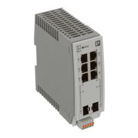
Phoenix Contact FL SWITCH 2108 Installation And Startup Manual (228 pages)
Brand:
Phoenix Contact
| Category:
Switch
| Size: 4 MB
Table of Contents
Table of Contents
3
Product Changes
7
For Your Safety
7
Qualification of Users
7
Identification of Warning Notes
7
Unauthorized Network Access
8
Properties of the Devices
9
Properties and Versions
9
FL SWITCH 2Xxx Device Versions
9
FL NAT 2Xxx Device Versions
11
Description of Ethernet Interfaces
11
Device Functions
12
Overview Table of the Functions
12
Status and Diagnostic Indicators
14
Description of the Integrated Fiberglass Transceivers
15
Description of the Combo Ports
15
Integrated Fiberglass Transceivers with an SC Pin Connector
15
Using the SFP Slots (Principle)
16
Elements of the SFP Modules
16
Mounting the SFP Modules
16
Inserting the SFP Modules (Example)
16
Using the (Micro)Sd Card
17
Position of the SD Card Slot (Left) and Position of the MI
17
Assignment of the Ethernet Connectors
19
Pin Assignment of RJ45 Connectors
19
Mounting and Installation
19
Functional Grounding
19
General Information
19
Pin Assignment of D-Coded M12 Connectors
20
Pin Assignment of X-Coded M12 Connectors
20
Dimensions of 16-Port Versions in a Narrow Housing
21
Device Dimensions
21
FL SWITCH 20Xx/21Xx/22Xx/23Xx and FL NAT 2Xxx
21
Elements of the Devices
22
Elements of the FL SWITCH 20Xx/21Xx/22Xx/23Xx and
22
Key for FL SWITCH 20Xx/21Xx/22Xx/23Xx and FL NAT 2Xxx
22
Mounting and Removing the Devices
22
Snapping the Device Onto the DIN Rail
23
Removing the Device
23
Installing the Devices
24
Selection of Conductors/Ferrules/Screwdrivers
24
Selecting the Conductors
24
Specifications for Ferrules
25
Operating the Device with One Power Supply (Example)
25
Redundant Operation with Two Power Supplies (Example)
25
Connecting a Relay to the Digital Alarm Output
26
FL SWITCH 20Xxf
27
Device Dimensions
27
Elements of the Devices
27
Dimensions of the 8-Port Version in a Flat Housing
27
Elements of the FL SWITCH 20Xxf Devices
27
Key for FL SWITCH 20Xxf
27
Mounting and Removing the Devices
28
Specifications for Ferrules
29
Selection of Conductors/Ferrules
29
Installing the Devices
29
FL SWITCH 24Xx/25Xx
30
Device Dimensions
30
Dimensions of 16-Port Versions
30
Elements of the Devices
31
Mounting and Removing the Devices
31
Elements of the FL SWITCH 24Xx/25Xx Devices
31
Key for FL SWITCH 24Xx/25Xx
31
Removing the Device
32
Installing the Devices
33
Supplying the Switch Using One Voltage Source
34
Supplying the Switch Using Two Voltage Sources
34
FL SWITCH 26Xx/27Xx
36
Device Dimensions
36
Elements of the Devices
36
Dimensions of the FL SWITCH 26Xx/27Xx Devices
36
Elements of the FL SWITCH 26Xx/27Xx Devices
36
Key for FL SWITCH 26Xx/27Xx
37
Figure 324 Drill Holes
37
Mounting and Removing the Devices
37
Installing the Devices
38
Pin Assignment for the Power Supply Via M12 Connectors with
38
Startup and Function
41
Delivery State/Factory Default
41
Initial IP Configuration in the Delivery State
41
Configuration in the Delivery State
42
Using Smart Mode
43
Entering Smart Mode
43
Selecting the Desired Setting
43
Operation in Universal Mode
44
Exiting Smart Mode
44
Possible Operating Modes in Smart Mode
44
Operation in PROFINET Mode
45
Operation in Ethernet/Ip Mode
45
Operation with Default IP Address
45
Resetting the IP Configuration
45
Operation in Unmanaged Mode
46
Assigning IP Parameters Via Bootp
46
Assigning the IP Address Using FL NETWORK MANAGER BASIC
47
Figure 41 Settings for the Bootp Server
47
Figure 42 Bootp Server
48
Figure 43: FL NETWORK MANAGER with Bootp/Dhcp Reservation List
48
Assigning the IP Address Using Ipassign.exe
49
Figure 44 "IP Address Request Listener" Window
49
Figure 45 "Set IP Address" Window with Incorrect Settings
50
Figure 46 "Assign IP Address" Window
50
Technical Data
53
Fl Switch 2005
53
Fl Switch 2008
55
Fl Switch 2008F
57
Fl Switch 2016
59
Fl Switch 2105
61
Fl Switch 2108
64
Fl Switch 2116
66
Fl Switch 2205
68
Fl Switch 2208
71
Fl Switch 2208C
73
Fl Switch 2208 Pn
75
Fl Switch 2207-Fx
78
Fl Switch 2207-Fx Sm
81
Fl Switch 2206-2Fx
83
Fl Switch 2206C-2Fx
86
Fl Switch 2206-2Fx Sm
89
Fl Switch 2206-2Fx St
91
Fl Switch 2206-2Fx Sm St
94
Fl Switch 2206-2Sfx
97
Fl Switch 2206-2Sfx Pn
99
Fl Switch 2204-2Tc-2Sfx
102
Fl Switch 2216
105
Fl Switch 2216 Pn
107
Fl Switch 2214-2Fx
110
Fl Switch 2214-2Fx Sm
113
Fl Switch 2214-2Sfx
115
Fl Switch 2214-2Sfx Pn
118
Fl Switch 2212-2Tc-2Sfx
121
Fl Switch 2308
124
Fl Switch 2308 Pn
126
Fl Switch 2306-2Sfp
129
Fl Switch 2306-2Sfp Pn
131
Fl Switch 2304-2Gc-2Sfp
134
Fl Switch 2316
137
Fl Switch 2316 Pn
139
Fl Switch 2314-2Sfp
142
Fl Switch 2314-2Sfp Pn
144
Fl Switch 2312-2Gc-2Sfp
147
Fl Switch 2408
150
Fl Switch 2408 Pn
152
Fl Switch 2406-2Sfx
154
Fl Switch 2406-2Sfx Pn
157
Fl Switch 2404-2Tc-2Sfx
159
Fl Switch 2416
162
Fl Switch 2416 Pn
165
Fl Switch 2414-2Sfx
167
Fl Switch 2414-2Sfx Pn
170
Fl Switch 2412-2Tc-2Sfx
172
Fl Switch 2508
175
Fl Switch 2508/K1
177
Fl Switch 2508 Pn
179
Fl Switch 2506-2Sfp
182
Fl Switch 2506-2Sfp/K1
184
Fl Switch 2506-2Sfp Pn
187
Fl Switch 2504-2Gc-2Sfp
189
Fl Switch 2516
192
Fl Switch 2516 Pn
194
Fl Switch 2514-2Sfp
197
Fl Switch 2514-2Sfp Pn
199
Fl Switch 2512-2Gc-2Sfp
202
Fl Switch 2608
204
Fl Switch 2608 Pn
206
Fl Switch 2708
208
Fl Switch 2708 Pn
210
Fl Nat 2008
212
Fl Nat 2208
214
Fl Nat 2304-2Gc-2Sfp
216
A Appendix For Document Lists
221
A 1 List of Figures
221
A 2 List of Tables
223
Advertisement
Phoenix Contact FL SWITCH 2108 User Manual (98 pages)
Brand:
Phoenix Contact
| Category:
Switch
| Size: 1 MB
Table of Contents
Table of Contents
2
Factoryline SWITCH 2000 Range
7
Fl Switch 2207-Fx
7
Dimensions of the FL SWITCH 2000
8
Elements of the Devices
9
Description of the Combo Ports
9
Status and Diagnostic Indicators
10
Mounting and Installation
11
Mounting and Removing the Devices
11
Properties and Versions
7
Order no
11
Installing the Devices
12
Connecting the Supply Voltage
12
Redundant Operation with Two Power Supplies (Example)
13
Connecting a Relay to the Digital Alarm Output
13
Order no
13
Grounding
14
Assignment of the RJ45 Ethernet Connectors
14
Use of SFP Slots (Principle)
14
Elements of the SFP Modules
15
Inserting the SFP Modules (Example)
15
Using the SD Card
16
Startup and Function
17
Delivery State/Factory Settings
17
Using Smart Mode
17
Calling Smart Mode
17
Factoryline SWITCH 2000 Range3.2.2Selecting the Desired Setting
18
Possible Operating Modes in Smart Mode
18
Exiting Smart Mode
18
Operating with a Default IP Address
18
Operating in Unmanaged Mode
19
Assigning IP Parameters Via Bootp
19
Assigning the IP Address Using
19
FL NETWORK MANAGER Basic
19
Order no
19
Bootp Server
20
Assigning the IP Address Using Ipassign.exe
21
FL Network Manager with Bootp/Dhcp Reservation List Displayed
21
Frame Switching
25
Store and Forward
25
Multi-Address Function
25
Learning Addresses
25
Prioritization
26
Configuration and Diagnostics in Web-Based Management
27
Requirements for the Use of WBM
27
Login Window
27
Functions/Information in WBM
28
Information Area of WBM
29
Help & Documentation" Web Page
29
Figure 5-6 "Local Diagnostics" Web Page
31
Figure 5-7 "Alarm & Events" Web Page
31
Figure 5-8 "Port Table" Web Page
32
Figure 5-9 "MAC Address Table" Web Page
32
Configuration Area of WBM
33
Figure 5-10 "System" Web Page
33
Figure 5-11 "Firmware Update Via HTTP" Pop-Up
34
Figure 5-12 "Firmware Update Via TFTP" Pop-Up
34
Figure 5-13 "Advanced Configuration" Pop-Up
36
Figure 5-14 "Advanced Configuration" Pop-Up
37
Figure 5-15 "Security Context" Pop-Up
37
Figure 5-16 "Administrator Password" Configuration Area
38
Figure 5-17 "Quick Setup" Web Page
38
Figure 5-18 "Network" Web Page
39
Figure 5-19 ACD Status Information on the "Device Status" Page
40
Figure 5-20 "Service" Web Page
40
Figure 5-21 "Port Configuration" Web Page
41
Figure 5-22 "Port Configuration Table" Web Page
43
Figure 5-23 "VLAN Configuration" Web Page
43
Figure 5-24 "Multicast Filtering" Web Page
44
Figure 5-25 "Spanning-Tree Configuration" Configuration Area
44
Figure 5-26 "RSTP Port Configuration" Web Page
46
Figure 5-33 "RSTP Diagnostic" Web Page
52
Figure 5-34 "MRP Diagnostic" Web Page
53
Figure 5-35 "Port Mirroring" Web Page
53
Figure 5-36 "Trap Manager" Web Page
54
Figure 5-37 "Port Counter" Web Page
55
Figure 5-38 "Port Utilization" Web Page
55
Figure 5-39 "SFP Diagnostics" Web Page
56
Command Terminal in Putty
57
Figure 6-1 Configuration of a Telnet Connection in Putty
57
Basic Principles for Using CLI Commands
58
Command Terminal in Windows Command Prompt
58
Establishing a Telnet Connection Via Windows Command Prompt
58
Command Syntax
59
Using the CLI Help
59
Auto-Completion of Commands
60
Using the CLI Network Scripting UI
61
General Function
63
Simple Network Management Protocol (SNMP)
63
Basics
65
Link Layer Discovery Protocol (LLDP)
65
Access to the CLI
57
Configuration and Diagnostics Via Command Line Interface (CLI)
57
Using the Command Line Interface (CLI)
57
Figure 5-27 "RSTP Port Configuration Table" Web Page
47
Figure 5-28 "Security" Web Page
47
Figure 5-29 "DHCP Service" Web Page
48
Figure 5-30 "DHCP Port Local Service" Pop-Up
49
Figure 5-31 "Local Events" Web Page
50
Figure 5-32 "Quality of Service" Web Page
51
Diagnostics Area of WBM
52
Link Layer Discovery Protocol" Web Page
66
LLDP Topology" Web Page
67
Multicast Filtering
69
Multicast Configuration
69
Multicast Filtering" Web Page
69
Current Multicast Groups" Web Page
70
Virtual Local Area Network (VLAN)
71
VLAN Configuration" Web Page
71
VLAN Port Configuration Table" Web Page
73
11 Technical Data and Ordering Data
75
Technical Data for Devices in the 2000 Version
75
Technical Data for Devices in the 2100 Version
76
Technical Data for Devices in the 2200 Version
78
VLAN Port Configuration" Web Page
73
Fl Switch 2206-2Fx St
79
Fl Switch 2206-2Fx Sm St
80
Technical Data for Devices in the 2300 Version
81
Ordering Data
85
Fl Switch 2204-2Tc-2Sfx
85
A Appendix For Document Lists
89
List of Figures
89
List of Tables
93
C 3 Index
95
Advertisement
Related Products
Phoenix Contact FL SWITCH 2105
Phoenix Contact FL SWITCH 2116
Phoenix Contact 2989543
Phoenix Contact FL SWITCH 2308
Phoenix Contact FL SWITCH 2306-2SFP
Phoenix Contact 2702333
Phoenix Contact FL SWITCH 2316
Phoenix Contact 2702324
Phoenix Contact 2702327
Phoenix Contact 2702907
Phoenix Contact Categories
Controller
Switch
Power Supply
Control Unit
Industrial Equipment
More Phoenix Contact Manuals
Login
Sign In
OR
Sign in with Facebook
Sign in with Google
Upload manual
Upload from disk
Upload from URL