Sign In
Upload
Manuals
Brands
Kongsberg Manuals
Marine Equipment
Simrad CP60
Kongsberg Simrad CP60 Manuals
Manuals and User Guides for Kongsberg Simrad CP60. We have
2
Kongsberg Simrad CP60 manuals available for free PDF download: Installation Manual, Instruction Manual
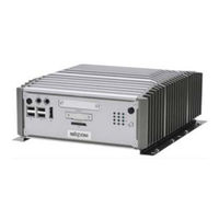
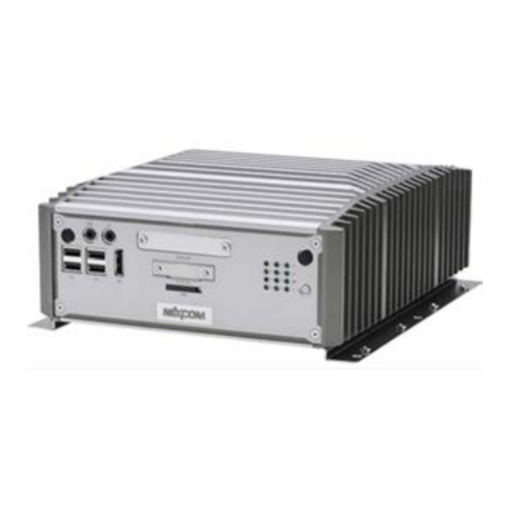
Kongsberg Simrad CP60 Installation Manual (260 pages)
Current profiler
Brand:
Kongsberg
| Category:
Marine Equipment
| Size: 3 MB
Table of Contents
Table of Contents
3
About this Manual
9
Simrad Cp60
11
Important
12
System Description
13
System Diagram
15
Main System Units
16
Display Description
16
Processor Unit Description
17
Wide Band Transceiver (WBT) Description
18
Transducer Description
19
Scope of Supply
20
General Safety Rules
21
Installation Requirements
23
Supply Voltage Requirements
23
Uninterruptible Power Supply (UPS) Requirements
23
Cables and Wiring Requirements
24
Compass Deviation Requirements
24
Noise Sources
24
Dry Docking Requirements
25
Requirement for Classification Approval
25
Network Security
26
Support Information
27
Preparations
29
Related Topics Preparations
29
Installation Summary
30
About Installation Drawings
32
Tools, Equipment and Consumables Required for Installation
32
Personnel Qualifications
33
Sonar Room Requirements
34
About the Sonar Room
34
Environmental Requirements
34
Requirements for Watertight Integrity
35
Size and Access Requirements
35
Requirements for Insulation, Heating and Ventilation
36
Requirements for Electrical Installations, Cables and Communication
37
Requirements for Bilge Pump and Decking
38
Where to Install the Transducer
39
Mount the Transducer Deep
39
Avoid Protruding Objects Near the Transducer
40
Mount the Transducer at Forward Part of Hull to Minimize the Effects from the Flow Boundary Water Layer
41
Keep the Transducer Far Away from the Propellers
42
Mount the Transducer at a Safe Distance from Bow Thruster(S)
42
Summary and General Recommendations
42
Acoustic Noise
45
Contributing Factors
45
Self Noise
47
Ambient Noise
49
Fishing Gear Noise
50
Electrical Self Noise
50
Some Means to Reduce Acoustic Noise
50
Vessel Coordinate System
52
Installing the Cp60 System Hardware Units
55
Installing the Wide Band Transceiver (WBT) Using the Integrated Brackets
56
Installing the Wide Band Transceiver (WBT) in a 19" Rack
58
Installing the WBT Power Supply
60
Installing the Display
62
Installing the Nexcom NISE 3900E Processor Unit
63
Installing a Commercial Computer
64
Installing the Transducer(S)
66
Cable Layout and Interconnections
68
Read this First
69
Reducing Electrical Noise
70
Cable Plans
71
About the Cable Plans
71
Topside Cable Plan
72
Sonar Room Cable Plan
74
List of Cables
75
List of Topside Cables
75
List of Sonar Room Cables
76
Comments
77
Installing the CP60 Cables
79
Prerequisites for Cable Installation
79
Installing the Topside Cables
80
Installing the Sonar Room Cables
81
Processor Unit Front Panel Description: Nexcom NISE 3900E
83
Processor Unit Rear Panel Description: Nexcom NISE 3900E
84
Wide Band Transceiver (WBT) Connectors
87
Using a Steel Conduit to Protect the Transducer Cable
88
Splicing the Transducer Cable
90
Cable Drawings and Specifications
93
DC Power Cable
94
RS-232 Serial Line Connection Using Three Wires
95
RS-232 Serial Line Connection Using Five Wires
96
Serial Line Connection Using Five Wires
97
RS-485 Serial Line Connection Using Three Wires
98
Used as Synchronization Trigger (Input or Output)
99
RJ45 High Speed Ethernet Cable (1000Base-T)
100
Remote Control Cable
101
Battery Power Cable (WBT)
102
K-Sync Interface to Generic RS-232 Synchronization Input
103
Simrad TU40 Interface to Generic RS-232 Synchronization Input
105
Auxiliary Connector for Synchronization (WBT)
107
Setting to Work
108
Setting to Work Summary
109
Making Sure that the CP60 Is Ready for Operational Use
111
Making Sure that the AC Mains Supply Voltage Is Correct
111
Making Sure that All CP60 System Cables Are Properly Connected
112
Visual Inspection of the Display
113
Visual Inspection of the Processor Unit
115
Visual Inspection of the Wide Band Transceiver (WBT)
116
Turning on the CP60 System for the First Time
119
Setting up Summary
119
Installing the CP60 Operating Software
121
Turning on the CP60 System for Passive Mode
122
Obtaining and Installing the Software License
123
Defining the IP Address on the Processor Unit Network Adapter for Communication with the Transceiver
125
Installing One or more Transducers
126
Installing Transceiver Channels
128
Adjusting the Screen Resolution
131
Restoring Correct Scaling of the CP60 Presentation
132
Configuring the CP60 System for Normal Operation
134
Selecting Menu Language
134
Selecting Measurement Units
135
Defining the File and Folder Settings for Data Recording
136
Placing each Sensor in the Vessel Coordinate System
138
Dimensional Surveying
138
Surveying the Transducer and the Navigation Sensors
139
Example Procedure
140
Vessel Coordinate System
143
Interfacing Peripheral Equipment
146
Installing Navigation Sensors and Other Sensors
146
Defining the Serial and Ethernet (LAN) Port Parameters
148
Setting up the Input from a Navigation System (GPS)
149
Configuring the Sensor Interface
152
Setting up a Serial or LAN (Ethernet) Port for Annotation Input
153
Connecting a Catch Monitoring System to a Serial or LAN (Ethernet) Port
155
Connecting a Trawl System to a Serial or LAN (Ethernet) Port
157
Setting up the Input from a Motion Reference Unit (MRU)
159
Setting up Depth Output to an External System
161
Exporting Sensor Data to a Peripheral System
163
Setting up Data Export to Olex
166
Synchronizing the CP60 by Means of a Serial Port
167
Synchronizing the CP60 System by Means of the Auxiliary Port
170
Test Procedures
173
Functional Test of the CP60 Current Profiler
174
Measuring Noise in Passive Operating Mode
176
Reading the Transceiver Hardware and Software Versions
178
Verifying the Communication with the Course Gyro
180
Verifying the Communication with a Navigation System (GPS)
182
Verifying the Communication with Speed Log
184
Verifying the Communication with the Motion Reference Unit (MRU)
186
Verifying the Communication with a Synchronization System
188
Making a Noise/Speed Curve to Determine Vessel Noise
190
Setting up the CP60 System for Synchronized Operation
194
About Synchronization
194
Synchronization Modes
195
Synchronization Sequences
196
Synchronization Using Clear to Send (CTS) and Request to Send (RTS) Signals
197
Synchronization Using the Auxiliary Socket on the Transceiver
197
Synchronizing the CP60 by Means of a Serial Port
199
Synchronizing the CP60 System by Means of the Auxiliary Port
202
Turning off the CP60 System
204
Installation Remarks
205
Technical Specifications
206
Introduction to Technical Specifications
207
Inputs
208
Supported Datagram Formats for Annotation Data
208
Supported Datagram Formats for Distance Information
208
Supported Datagram Formats for Drop Keel Offset Information
209
Supported Datagram Formats for GPS (Position) Information
209
Supported Datagram Formats for Heading and Gyro Information
210
Supported Datagram Formats for Trawl Information
210
Supported Datagram Formats for Motion Information
211
Supported Datagram Formats for Palette Control
212
Supported Datagram Formats for Catch Monitoring Information
212
Supported Datagram Formats for Speed Log Information
213
Supported Datagram Formats for Temperature Information
214
Supported Datagram Formats for Water Level Offset Information
214
Outputs
215
Supported Datagram Formats for Velocity Information
215
Supported Datagram Formats for Depth Outputs
216
Weights and Outline Dimensions
217
Display Weight and Outline Dimensions
217
Nexcom NISE 3900E Processor Unit Weight and Outline Dimensions
217
Wide Band Transceiver (WBT) Weight and Outline Dimensions
218
Power Requirements
219
Display Power Requirements
219
Nexcom NISE 3900E Processor Unit Power Requirements
219
Wide Band Transceiver (WBT) Power Requirements
220
WBT Power Supply Power Requirements
220
Environmental Requirements
221
Display Environmental Requirements
221
Nexcom NISE 3900E Processor Unit Environmental Requirements
221
Wide Band Transceiver (WBT) Environmental Requirements
222
Compass Safe Distance
223
Display Compass Safe Distance
223
Nexcom NISE 3900E Processor Unit Compass Safe Distance
223
Wide Band Transceiver (WBT) Compass Safe Distance
224
WBT Power Supply Compass Safe Distance
224
Minimum Computer Requirements
224
Minimum Display Requirements
226
Drawing File
228
About the Drawings in the Drawing File
229
388697 Wide Band Transceiver (WBT) Outline Dimensions
230
Nexcom NISE 3900E Outline Dimensions
232
201575 Transducer Connector Assembly and Wiring
234
Equipment Handling
235
Transporting Kongsberg Maritime Equipment
236
Lifting Units and Transportation Boxes
237
Inspection of Units and Transportation Boxes after Arrival
238
Specifications for Storage Prior to Installation or Use
239
Unpacking Instructions
240
Unpacking Standard Parts and Units
241
Unpacking Mechanical Units
242
Unpacking Electronic and Electromechanical Units
243
Unpacking Transducers
244
Specifications for Storage after Unpacking
245
Advertisement
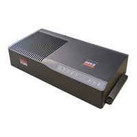
Kongsberg Simrad CP60 Instruction Manual (42 pages)
Brand:
Kongsberg
| Category:
Marine Equipment
| Size: 0 MB
Table of Contents
Table of Contents
3
About this Manual
5
Introduction
7
About Current Indicator Calibration
7
Calibration Summary
8
Support Information
9
Preparations
12
Calibrating the Current Indicator
12
Obtaining and Installing the Software License for Raw Data Recording
14
Selecting the Location for Current Indicator Calibration
15
Configuring the Environmental Parameters
16
Importing the Water Temperature from the Transducer
17
Configuring the Sensor Priority for Current Indicator Calibration
18
Inserting the Installation Parameters for the Global Positioning System (GPS) Antenna and the Transducer
20
Defining the File and Folder Settings for Raw Data Recording
23
Defining the Bottom Detection Parameters for the Calibration
24
Preparing the Echo Sounder System for Current Indicator Calibration
26
Calibrating the Current Velocity Measurements
28
Recording Raw Data
28
Collecting Data for Current Indicator Calibration
29
Processing Data for Current Indicator Calibration
33
Functions and Dialog Boxes
35
Calibration Function
35
Calibration Wizard Dialog Box #1
36
Calibration Wizard Dialog Box #2
37
Calibration Wizard Dialog Box #3
38
Advertisement
Related Products
Kongsberg Simrad CS90
Kongsberg Simrad EM 300
Kongsberg Simrad EK80
Kongsberg Simrad FS70
Kongsberg SIMRAD 22092100
Kongsberg SIMRAD 22092142
Kongsberg Simrad TV80
Kongsberg Simrad ES80
Kongsberg Simrad NISE 3900E
Kongsberg Simrad WP32
Kongsberg Categories
Marine Equipment
Sonar
Marine Radio
Transceiver
Autopilot System
More Kongsberg Manuals
Login
Sign In
OR
Sign in with Facebook
Sign in with Google
Upload manual
Upload from disk
Upload from URL