Table of Contents
Advertisement
Quick Links
Preliminary version 2022-07-26
This manual provides you with the basic information required to install
the Simrad CP60 Current profiler. The manual is intended for technical
personnel; such as skilled shipyard workers, electricians, qualified
engineers and naval architects.
For information about the practical use of the CP60 system, refer to the
Reference Manual and/or the context sensitive On-line help.
Caution
You must never permit the CP60 system to transmit (ping) when the
ship is in dry dock. The transducer may be damaged if it transmits
in open air.
Additional end-user documents related to the CP60 system can be
found on our website. This includes publications that are translated to
other languages. Selected publications are also provided on IETM
(Interactive Electronic Technical Manual) formats.
• www.kongsberg.com/cp60
Simrad CP60
Current profiler
Installation Manual
110-0006927/A (Preliminary)
July 2022 © Kongsberg Maritime AS
Advertisement
Table of Contents

Subscribe to Our Youtube Channel
Related Manuals for Kongsberg Simrad CP60


Summary of Contents for Kongsberg Simrad CP60
- Page 1 Current profiler Installation Manual This manual provides you with the basic information required to install the Simrad CP60 Current profiler. The manual is intended for technical personnel; such as skilled shipyard workers, electricians, qualified engineers and naval architects. For information about the practical use of the CP60 system, refer to the Reference Manual and/or the context sensitive On-line help.
- Page 2 Kongsberg Maritime disclaims any responsibility for damage or injury caused by improper installation, use or maintenance of the equipment. Disclaimer Kongsberg Maritime AS endeavours to ensure that all information in this document is correct and fairly stated, but does not accept liability for any errors or omissions. Support information If you require maintenance or repair, contact your local dealer.
-
Page 3: Table Of Contents
Preliminary version 2022-07-26 Installation Manual Table of contents ABOUT THIS MANUAL .............. 9 SIMRAD CP60 ................ 11 Important..........................12 System description ......................13 System diagram........................15 Main system units ......................16 Display description....................16 Processor Unit description..................17 Wide Band Transceiver (WBT) description ............18 Transducer description ...................19 Scope of supply........................20... - Page 4 Preliminary version 2022-07-26 Simrad CP60 Avoid protruding objects near the transducer............40 Mount the transducer at forward part of hull to minimize the effects from the flow boundary water layer .................41 Keep the transducer far away from the propellers ..........42 Mount the transducer at a safe distance from bow thruster(s) .......42 Summary and general recommendations ...............42...
- Page 5 Preliminary version 2022-07-26 Installation Manual Using a steel conduit to protect the transducer cable ..........88 Splicing the transducer cable..................90 Cable drawings and specifications ...................93 DC Power cable......................94 RS-232 serial line connection using three wires ............95 RS-232 serial line connection using five wires ............96 RS-422 serial line connection using five wires ............97 RS-485 serial line connection using three wires ............98 RS-232 used as synchronization trigger (input or output) ........99...
- Page 6 Preliminary version 2022-07-26 Simrad CP60 Surveying the transducer and the navigation sensors...........139 Example procedure....................140 Vessel coordinate system..................143 Interfacing peripheral equipment...................146 Installing navigation sensors and other sensors ...........146 Defining the serial and Ethernet (LAN) port parameters ........148 Setting up the input from a navigation system (GPS) ..........149 Configuring the sensor interface................152...
- Page 7 Preliminary version 2022-07-26 Installation Manual Inputs ..........................208 Supported datagram formats for annotation data ..........208 Supported datagram formats for distance information.........208 Supported datagram formats for drop keel offset information......209 Supported datagram formats for GPS (position) information ......209 Supported datagram formats for heading and gyro information ......210 Supported datagram formats for trawl information..........210 Supported datagram formats for motion information...........
- Page 8 Preliminary version 2022-07-26 Simrad CP60 201575 Transducer connector assembly and wiring............234 EQUIPMENT HANDLING............235 Transporting Kongsberg Maritime equipment...............236 Lifting units and transportation boxes ................237 Inspection of units and transportation boxes after arrival..........238 Specifications for storage prior to installation or use.............239 Unpacking instructions ....................240...
-
Page 9: About This Manual
Note Kongsberg Maritime AS will accept no responsibility for any damage or injury to the product, vessel or personnel caused by equipment that has been incorrectly installed or maintained, or by drawings, instructions or procedures that have not been prepared by us. - Page 10 All end-user manuals provided for operation and installation of your CP60 system can be downloaded from our website. • www.kongsberg.com/cp60 Our website also provides information about other products from Kongsberg Maritime. Registered trademarks Observe the registered trademarks that apply. Windows ®...
-
Page 11: Simrad Cp60
Preliminary version 2022-07-26 Simrad CP60 Simrad CP60 Topics Important, page 12 System description, page 13 System diagram, page 15 Main system units, page 16 Scope of supply, page 20 General safety rules, page 21 Installation requirements, page 23 Network security, page 26... -
Page 12: Important
Preliminary version 2022-07-26 Simrad CP60 Installation Manual Important The CP60 is an advanced product. It is used with other advanced products. There is important information that you need to know. Before you turn on the CP60 system Before you turn on the CP60 system, make sure that the transducer is submerged in water. -
Page 13: System Description
Simrad CP60, page 11 System description The Simrad CP60 is a cost-effective current profiler. It can measure current in up to 5 layers of current individually set by the user in the water column. The measurements provided are the speed of the current and the NSWE direction. A backscatter display for each channel is also present. - Page 14 Preliminary version 2022-07-26 Simrad CP60 Installation Manual The current measurements can be seen on the right of the picture in a numeric view and a PPI view with arrows. You can also get Speed Over Ground (SOG) and Course Over Ground (COG).
-
Page 15: System Diagram
Unless otherwise specified in a contract, the display and the Ethernet switch are not included in the standard delivery. These are commercial items that can be purchased locally. Display Processor Unit Wide Band Transceiver (WBT) ADCP transducer Split-beam transducer Related topics Simrad CP60, page 11 110-0006927/A (Preliminary) -
Page 16: Main System Units
The chosen display must be designed for maritime use, and it must meet the minimum performance specifications. You must also make sure that the chosen display supports the video formats provided by the computer. Kongsberg Maritime may provide a suitable display. -
Page 17: Processor Unit Description
A suitable computer can be provided with the CP60 system. It has been customized by Kongsberg Maritime. The computer is based on a commercial design, but the software and hardware have been specified by Kongsberg Maritime to suit the CP60 requirements. -
Page 18: Wide Band Transceiver (Wbt) Description
Preliminary version 2022-07-26 Simrad CP60 Installation Manual The Processor Unit provides multiple USB ports. You can use a USB flash drive to download screen captures. You can connect a USB flash drive to upgrade the CP60 system software. USB ports can also be used to connect a keyboard and a mouse for maintenance tasks. -
Page 19: Transducer Description
The CP60 Current profiler can be used with all our single-beam and split-beam transducers. An ADCP transducer can also be connected to the CP60. Kongsberg Maritime can provide a wide range of efficient and accurate Simrad transducers for the CP60 Current profiler. -
Page 20: Scope Of Supply
Additional items are required for operation. These items must be added to the CP60 system for full operational functionality. Some items are optional. Such items can be purchased from Kongsberg Maritime or obtained locally. -
Page 21: General Safety Rules
Preliminary version 2022-07-26 Simrad CP60 General safety rules Safety is important. The safety precautions must be followed at all times during installation and maintenance work. WARNING The CP60 system operates on 110 VAC and/or 230 VAC at 50/60 Hz. This voltage... - Page 22 Preliminary version 2022-07-26 Simrad CP60 Installation Manual Cabinets Do not open racks or cabinet doors while sailing in rough seas. Doors and/or cabinet parts may suddenly swing open and cause damage or injury. Related topics Simrad CP60, page 11 110-0006927/A (Preliminary)
-
Page 23: Installation Requirements
Maximum transient voltage variations on the main switchboard’s bus-bars must not exceed -15% to +20% of the nominal voltage (except under fault conditions). Related topics Simrad CP60, page 11 Installation requirements, page 23 Uninterruptible power supply (UPS) requirements We recommend that the CP60 system is powered using an Uninterruptible Power Supply (UPS) with sine wave output. -
Page 24: Cables And Wiring Requirements
Preliminary version 2022-07-26 Simrad CP60 Installation Manual Cables and wiring requirements Correct wiring is crucial for the operational performance of the CP60 system. All cables running between system cabinets located in different rooms and/or on different decks must be supported and protected along their entire lengths using conduits and/or cable trays. -
Page 25: Dry Docking Requirements
Ensure maximum physical distance between the transceiver and the power supply. This is important to reduce noise. Related topics Simrad CP60, page 11 Installation requirements, page 23 Dry docking requirements Whenever one or more transducers are mounted under the vessel’s hull, special considerations must be made prior to dry docking. -
Page 26: Network Security
The damage done if a remote computer succeeds doing this. Kongsberg Maritime has no information regarding the complete system installation on any vessel. Systems provided by Kongsberg Maritime are regarded as stand-alone offline systems. They are stand-alone even though they may be connected to a network for sensor interfaces and/or data distribution. -
Page 27: Support Information
Telefax • www.kongsberg.com/simrad Website • simrad.france@simrad.com Email address • : Kongsberg Underwater Technology LLC (KUTL) / Simrad Fisheries Company name • : 19210 33rd Ave W, Suite A, Lynnwood, WA 98036, USA Address • : +1 425 712 1136 Telephone •... - Page 28 Website • simrad.canada@simrad.com Email address Malaysia • : Kongsberg Maritime Malaysia Sdn. Bhd Company name • : Unit 27-5 Signature Offices, The Boulevard, Mid Valley City, Address Lingkaran Syed Putra, 59200 Kuala Lumpur, Malaysia • : +65 6411 7488 Telephone •...
-
Page 29: Preparations
Preliminary version 2022-07-26 Preparations Preparations Topics Installation summary, page 30 About installation drawings, page 32 Tools, equipment and consumables required for installation, page 32 Personnel qualifications, page 33 Sonar room requirements, page 34 Where to install the transducer, page 39 Acoustic noise, page 45 Vessel coordinate system, page 52 110-0006927/A (Preliminary) -
Page 30: Installation Summary
Preliminary version 2022-07-26 Simrad CP60 Installation Manual Installation summary Installation of the CP60 system is a demanding task that requires careful preparations, a number of specific procedures, wiring and required system settings. Context An overall installation procedure is provided. This procedure does not describe any detailed tasks. - Page 31 Preliminary version 2022-07-26 Preparations Note The installation shipyard must provide all necessary design and installation drawings, as well as the relevant work standards and mounting procedures. If required, all documents provided by the shipyard for the physical installation of the CP60 system must be approved by the vessel’s national registry and corresponding maritime authority and/or classification society.
-
Page 32: About Installation Drawings
The shipowner and shipyard doing the installation are responsible for obtaining and paying for such approval. Kongsberg Maritime offers free advice for installation planning. Proposed arrangements may be sent for commentary or suggestions. The following drawings should be submitted should assistance be requested: •... -
Page 33: Personnel Qualifications
Preliminary version 2022-07-26 Preparations Related topics Preparations, page 29 Personnel qualifications The installation of the CP60 system is a demanding task. Installation tasks must only be done by fully trained personnel. As a minimum, the following certified personnel must be available: •... -
Page 34: Sonar Room Requirements
CP60 system units must be well protected against dust, dirt and damage. Kongsberg Maritime AS takes no responsibility for any failures or damage to CP60 system units that are caused by installation, maintenance or construction work in the sonar room. -
Page 35: Requirements For Watertight Integrity
Preliminary version 2022-07-26 Preparations Visit the sonar room at regular intervals to check for dust, high temperature and humidity. Take the necessary actions if the environmental conditions are poor. We recommended that you keep the ambient temperature between +5 and +40°C, and the relative humidity less than 80%. -
Page 36: Requirements For Insulation, Heating And Ventilation
Preliminary version 2022-07-26 Simrad CP60 Installation Manual The sonar room must be large enough to house all the system units. The room must provide enough space to allow efficient maintenance. You must be able to keep all the cabinet doors fully open without undue restriction to your movements. -
Page 37: Requirements For Electrical Installations, Cables And Communication
Preliminary version 2022-07-26 Preparations pipe. To keep out sea water, rain and spray, the ventilation pipes must be fitted with goosenecks or an equivalent design. Note If the vessel is likely to operate in tropical conditions, a suitable air conditioning system must be installed. -
Page 38: Requirements For Bilge Pump And Decking
Preliminary version 2022-07-26 Simrad CP60 Installation Manual Related topics Preparations, page 29 Sonar room requirements, page 34 Requirements for bilge pump and decking If the sonar room is located below the water line, it must be connected to the vessel's bilge pump system. -
Page 39: Where To Install The Transducer
Preliminary version 2022-07-26 Preparations Where to install the transducer A single answer to the question "where to install the transducer" cannot be given. The physical location of the transducer depends on the vessel's design and construction, how the hull is shaped, and how the water runs along the hull. There are however a number of important guidelines, and some of these are even conflicting. -
Page 40: Avoid Protruding Objects Near The Transducer
The effect of slamming can be reduced by mounting the transducer as deep as possible on the hull. Note Kongsberg Maritime AS takes no responsibility for any damages to the transducer, the cable or the mounting arrangement, caused by slamming. Related topics... -
Page 41: Mount The Transducer At Forward Part Of Hull To Minimize The Effects From The Flow Boundary Water Layer
Preliminary version 2022-07-26 Preparations Mount the transducer at forward part of hull to minimize the effects from the flow boundary water layer The upper water layers of the sea contain a myriad of small air bubbles created by the breaking waves. When the hull moves through water it will cause a disturbance, and this will generate friction. -
Page 42: Keep The Transducer Far Away From The Propellers
Preliminary version 2022-07-26 Simrad CP60 Installation Manual Keep the transducer far away from the propellers The propulsion propellers is the dominant noise source on most vessels. The noise is easily transmitted through the water. This noise may often reduce the overall performance of your CP60 transducer. - Page 43 Preliminary version 2022-07-26 Preparations The maximum distance from the bow is normally equal to one third of the total water line length of the hull. Note Mounting the transducer more than 10–15 meters from the bow may cause problems with the turbulent flow. Transducer Hull length at water line Inclination angle...
- Page 44 Preliminary version 2022-07-26 Simrad CP60 Installation Manual Important The transducer must not have a negative inclination angle compared to water flow. Do not place a transducer near protruding objects, and especially not close behind them. Make sure that the surface of the resulting installation is as smooth and streamlined as possible.
-
Page 45: Acoustic Noise
Preliminary version 2022-07-26 Preparations Acoustic noise As with any other hydroacoustic systems, the quality of the CP60 echo data and presentations are subject to unwanted acoustic noise. The echoes from any large and small target must be detected inside the noise. It is important that we keep the noise level as low as possible. - Page 46 Preliminary version 2022-07-26 Simrad CP60 Installation Manual expressed in decibels. A ratio higher than 1:1 (greater than 0 dB) indicates more signal than noise. While SNR is commonly quoted for electrical signals, it can be applied to any form of signal [...].
-
Page 47: Self Noise
Preliminary version 2022-07-26 Preparations The converters transform the analogue echoes to digital format. Signal processing circuitry can create digital noise. Related topics Preparations, page 29 Acoustic noise, page 45 Self noise Any vessel equipped with a hydroacoustic system (for example echo sounder or sonar) will produce more or less self noise. - Page 48 Preliminary version 2022-07-26 Simrad CP60 Installation Manual Cavitation Cavitation is the formation of small air bubbles close to the transducer face. The bubbles appear because the local pressure becomes negative during parts of the acoustic pressure cycles. The cavitation threshold increases with the hydrostatic pressure.
-
Page 49: Ambient Noise
Preliminary version 2022-07-26 Preparations thickness depends on ships speed and on the roughness of the hull. All objects sticking out from the hull, or dents in the hull, will disturb the flow and will increase the thickness of the boundary layer. When the flow speed is high, the turbulence can be violent enough to destroy the integrity of the water. -
Page 50: Fishing Gear Noise
Preliminary version 2022-07-26 Simrad CP60 Installation Manual Related topics Preparations, page 29 Acoustic noise, page 45 Fishing gear noise Whenever your fishing gear is in use, it will create noise. A bottom trawl, for instance, is a considerable source of acoustic noise. Still, this noise from the fishing gear will seldom be a limiting factor for hull mounted sonars or echo sounders. - Page 51 Preliminary version 2022-07-26 Preparations Note The information here must be considered as general advice. Each system installation must be handled separately depending on the hull design and the other electrical and mechanical systems installed on the vessel. Reducing flow noise The shape of the transducer (or dome around it) must be as streamlined as possible.
-
Page 52: Vessel Coordinate System
Preliminary version 2022-07-26 Simrad CP60 Installation Manual Reducing rattle noise Ensure that no parts near the transducers can rattle as a result of water flow or vibrations. Reducing interference Interference from the transmission pulses from other hydroacoustic instruments on board the vessel is difficult to avoid. The problem may be reduced by choosing the working frequencies carefully and to some extent by separating the different transducers. - Page 53 Preliminary version 2022-07-26 Preparations are physically positioned far away from the transducer, which may be located closer to the bow. Very often, the information from one sensor depends on data from an other. It is then important that the relevant measurements are compensated for these relative distances.
- Page 54 Preliminary version 2022-07-26 Simrad CP60 Installation Manual Coordinate system alternative origins If necessary, other origin locations may be defined for specific products or purposes. One example is the Navigation Reference Point that is frequently used. Whenever a vessel is surveyed to establish accurate offset information, the surveyor may also establish an alternative origin location.
-
Page 55: Installing The Cp60 System Hardware Units
Preliminary version 2022-07-26 Installing the CP60 system hardware units Installing the CP60 system hardware units Topics Installing the Wide Band Transceiver (WBT) using the integrated brackets, page 56 Installing the Wide Band Transceiver (WBT) in a 19" rack, page 58 Installing the WBT Power Supply, page 60 Installing the display, page 62 Installing the Nexcom NISE 3900E Processor Unit, page 63... -
Page 56: Installing The Wide Band Transceiver (Wbt) Using The Integrated Brackets
Preliminary version 2022-07-26 Simrad CP60 Installation Manual Installing the Wide Band Transceiver (WBT) using the integrated brackets The transceiver is normally positioned in a dedicated room in the vicinity of the transducer. The physical length of the cables limit the distance between each transducer and the transceiver. - Page 57 Preliminary version 2022-07-26 Installing the CP60 system hardware units Procedure Prepare the location and the necessary tools. Observe the installation requirements. Depending on the local requirements and preferences, the Wide Band Transceiver (WBT) can be installed on the bulkhead, inside a console, in a cabinet or 19”...
-
Page 58: Installing The Wide Band Transceiver (Wbt) In A 19" Rack
Preliminary version 2022-07-26 Simrad CP60 Installation Manual Installing the Wide Band Transceiver (WBT) in a 19" rack The Wide Band Transceiver (WBT) can be installed in a 19-inch rack by means of an optional drawer. You will need one drawer for each Wide Band Transceiver (WBT). - Page 59 Preliminary version 2022-07-26 Installing the CP60 system hardware units Procedure Prepare the location and the necessary tools. Observe the installation requirements. Depending on the local requirements and preferences, the Wide Band Transceiver (WBT) can be installed on the bulkhead, inside a console, in a cabinet or 19”...
-
Page 60: Installing The Wbt Power Supply
Preliminary version 2022-07-26 Simrad CP60 Installation Manual Installing the WBT Power Supply The power supply provided with the Wide Band Transceiver (WBT)is a commercial type custom made for the CP60. A dedicated installation procedure is provided. Prerequisites A suitable location for the power supply must be defined prior to installation. If you place the unit on the bridge, observe the compass safe distance. - Page 61 Preliminary version 2022-07-26 Installing the CP60 system hardware units Make sure that adequate ventilation is available to avoid overheating. Make sure that the installation method allows for the physical vibration, movements and forces normally experienced on a vessel. Note To allow future maintenance, you must mount the unit with its cables and connectors available for easy access.
-
Page 62: Installing The Display
Preliminary version 2022-07-26 Simrad CP60 Installation Manual Installing the display A display is a required part of the CP60 system. For best readability, the display must be protected from glare and have the correct height and angle. The display is normally not included with the CP60 system delivery. -
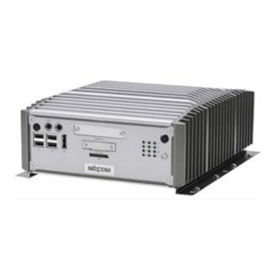
Page 63: Installing The Nexcom Nise 3900E Processor Unit
Preliminary version 2022-07-26 Installing the CP60 system hardware units Connect the cables. Note When you connect the cables, make sure that they are all properly secured, and able to withstand the vibration and movements of the vessel. Related topics Installing the CP60 system hardware units, page 55 Installing the Nexcom NISE 3900E Processor Unit The Processor Unit can be installed inside a console, inside a suitable cabinet, in a 19"... -
Page 64: Installing A Commercial Computer
Preliminary version 2022-07-26 Simrad CP60 Installation Manual Note To allow future maintenance, you must mount the unit with its cables and connectors available for easy access. Make sure that the chosen location meets the installation requirements. Provide ample space around the computer. - Page 65 Preliminary version 2022-07-26 Installing the CP60 system hardware units A suitable location for the computer must be defined prior to installation. Observe the compass safe distance. Context For installation of a commercial computer, refer to the manual supplied by the manufacturer.
-
Page 66: Installing The Transducer(S)
Preliminary version 2022-07-26 Simrad CP60 Installation Manual Provide ample space around the computer. You must be able to reach and use the front and rear mounted connectors and on/off switches. It is also important that you allow for easy access to all the computer cables, and enough space for inspection, maintenance and parts replacement. - Page 67 Preliminary version 2022-07-26 Installing the CP60 system hardware units Procedure Determine the physical location of the transducer. The decision must be based on: • The vessel drawings • The shape and properties of the hull Make sure that all possible considerations are made to reduce noise. Based on the shape of the transducer housing, and the mounting devices available, determine the installation method.
-
Page 68: Cable Layout And Interconnections
Preliminary version 2022-07-26 Simrad CP60 Installation Manual Cable layout and interconnections Topics Read this first, page 69 Reducing electrical noise, page 70 Cable plans, page 71 List of cables, page 75 Installing the CP60 cables, page 79 Cable drawings and specifications, page 93... -
Page 69: Read This First
Cable layout and interconnections Read this first Detailed information about cable specifications, termination and connectors is provided. Unless otherwise specified, all cables are supplied by Kongsberg Maritime as a part of the delivery. Detailed information about relevant cable specifications, termination and connectors is provided. -
Page 70: Reducing Electrical Noise
Preliminary version 2022-07-26 Simrad CP60 Installation Manual Reducing electrical noise These points must all be considered to reduce electrical noise on an CP60 system. Note The information here must be considered as general advice. • Place the transducer cables in a metal conduit all the way from the transducer to the transceiver. -
Page 71: Cable Plans
Preliminary version 2022-07-26 Cable layout and interconnections Cable plans Topics About the cable plans, page 71 Topside cable plan, page 72 Sonar room cable plan, page 74 About the cable plans Due to its modular design, the CP60 system can be set up in a variety of configurations to suit individual needs for operational frequencies, transducers and functionality. -
Page 72: Topside Cable Plan
Preliminary version 2022-07-26 Simrad CP60 Installation Manual Topside cable plan The topside/bridge cables include those used to connect the Processor Unit and the display to each other, as well as cables for AC mains power and external devices. One high capacity Ethernet cable connects the Processor Unit to the Wide Band Transceiver (WBT). - Page 73 Preliminary version 2022-07-26 Cable layout and interconnections We strongly recommend that you install minimum two Ethernet cables between the sonar room and the bridge. One cable is for operational use, while the other is spare. Related topics Cable layout and interconnections, page 68 Cable plans, page 71 List of topside cables, page 75 110-0006927/A (Preliminary)
-
Page 74: Sonar Room Cable Plan
Preliminary version 2022-07-26 Simrad CP60 Installation Manual Sonar room cable plan The sonar room is the compartment in which the transceiver is installed. The transceiver cables include those used to connect the transceiver(s) to AC mains power and to the transducer(s). -
Page 75: List Of Cables
Preliminary version 2022-07-26 Cable layout and interconnections List of cables A set of cables is required to connect the system units to each other, and to the relevant power source(s). Additional cables are required to connect the CP60 system to peripheral devices. -
Page 76: List Of Sonar Room Cables
Preliminary version 2022-07-26 Simrad CP60 Installation Manual Related topics Cable layout and interconnections, page 68 List of cables, page 75 Cable plans, page 71 Topside cable plan, page 72 Comments, page 77 List of sonar room cables Each cable used by the CP60 system in the sonar room is listed. -
Page 77: Comments
Preliminary version 2022-07-26 Cable layout and interconnections Comments Some of the cables used by the CP60 system require additional explanations and recommendations. Cable numbers Cable numbers that are not used are spares for optional equipment and/or future expansions. Project cables The CP60 system is often a part of a project delivery. - Page 78 Preliminary version 2022-07-26 Simrad CP60 Installation Manual C16 Remote control cable A dedicated socket on the rear side of the Processor Unit cabinet allows you to turn on the computer by means of a remote control switch. Note This functionality is specific for the Nexcom NISE 3900E computer.
-
Page 79: Installing The Cp60 Cables
Only skilled and authorized personnel can install the CP60 cables. Kongsberg Maritime will not accept any responsibility for errors, malfunctions or damage to system or personnel caused by improper wiring. 110-0006927/A (Preliminary) -
Page 80: Installing The Topside Cables
Preliminary version 2022-07-26 Simrad CP60 Installation Manual Related topics Cable layout and interconnections, page 68 Installing the CP60 cables, page 79 Installing the topside cables The topside/bridge cables include those used to connect the Processor Unit and the display to each other, as well as cables for AC mains power and external devices. One high capacity Ethernet cable connects the Processor Unit to the Wide Band Transceiver (WBT). -
Page 81: Installing The Sonar Room Cables
Preliminary version 2022-07-26 Cable layout and interconnections Connect the Ethernet cable from the Processor Unit to the Wide Band Transceiver (WBT). Note It is very important that high-quality Ethernet cables are used. You must use CAT-5E STP (Shielded Twisted Pair) quality or better. Using cables with lower bandwidth capacity will reduce performance. - Page 82 Preliminary version 2022-07-26 Simrad CP60 Installation Manual If you wish to use the synchronization method offered by the Auxiliary socket on the Wide Band Transceiver (WBT), make the necessary connection. Related topics Cable layout and interconnections, page 68 Installing the CP60 cables, page 79...
-
Page 83: Processor Unit Front Panel Description: Nexcom Nise 3900E
Preliminary version 2022-07-26 Cable layout and interconnections Processor Unit front panel description: Nexcom NISE 3900E The front panel of the Processor Unit holds interface ports, LED indicators and an on/off switch. USB 2.0 ports Graphics adapter (DisplayPort) Audio input/output Serial port (The number and physical location of the serial ports may differ from one computer model to another.) Note This computer exists in several versions. -
Page 84: Processor Unit Rear Panel Description: Nexcom Nise 3900E
Preliminary version 2022-07-26 Simrad CP60 Installation Manual Processor Unit rear panel description: Nexcom NISE 3900E The rear panel of the Processor Unit holds the power socket and multiple interface ports. DC power socket Remote control Serial ports (The number and physical location of the serial ports may differ from one computer model to another.) - Page 85 Preliminary version 2022-07-26 Cable layout and interconnections ETH3 Ship network Use this socket if you want to connect your CP60 system to the ship’s local area network (LAN). USB connectors The Processor Unit offers several USB interface sockets. The USB sockets can be used to interface peripheral devices such as USB flash drives, portable hard disks, mouse and keyboard.
- Page 86 Preliminary version 2022-07-26 Simrad CP60 Installation Manual COM3 This serial port is set up for RS232 communication. This serial communication format is fixed and cannot be changed. This serial port may not be fitted on all computer models. COM4 This serial port is set up for RS232 communication. This serial communication format is fixed and cannot be changed.
-
Page 87: Wide Band Transceiver (Wbt) Connectors
Preliminary version 2022-07-26 Cable layout and interconnections Wide Band Transceiver (WBT) connectors All connectors for the system cables are located on the side panel on the Wide Band Transceiver (WBT). Ground cable: From transceiver to vessel ground Transducer cable: From transceiver to transducer Ethernet cable: From transceiver to computer DC Power cable: From transceiver to power supply unit Auxiliary connector for synchronization (Optional) -
Page 88: Using A Steel Conduit To Protect The Transducer Cable
Preliminary version 2022-07-26 Simrad CP60 Installation Manual Using a steel conduit to protect the transducer cable A steel conduit must be used to protect the transducer cable. The steel conduit must preferably be straight. Start the conduit immediately above the transducer, and terminate it well above the water line. - Page 89 Preliminary version 2022-07-26 Cable layout and interconnections Related topics Cable layout and interconnections, page 68 Installing the CP60 cables, page 79 110-0006927/A (Preliminary)
-
Page 90: Splicing The Transducer Cable
• The necessary length of transducer cable. The cable between the junction box and the transceiver must be supplied by Kongsberg Maritime, and this must be the same type as used on the transducer. Electrical installations can only be done by certified electricians. All necessary tools and instruments required must be available. - Page 91 Preliminary version 2022-07-26 Cable layout and interconnections The junction box is isolated from vessel ground. Cable gland Terminal block Cable Cable screen (Do not connect the cable screen to vessel ground.) Procedure Mount the junction box in a suitable location. Terminate the steel conduits containing the transducer cable as close to the junction box as...
- Page 92 Preliminary version 2022-07-26 Simrad CP60 Installation Manual Junction box Cable gland Terminal block Cable Cable screen (Do not connect the cable screen to vessel ground.) The junction box may be connected to vessel ground. Procedure Mount the junction box in a suitable location.
-
Page 93: Cable Drawings And Specifications
Preliminary version 2022-07-26 Cable layout and interconnections Cable drawings and specifications Topics DC Power cable, page 94 RS-232 serial line connection using three wires, page 95 RS-232 serial line connection using five wires, page 96 RS-422 serial line connection using five wires, page 97 RS-485 serial line connection using three wires, page 98 RS-232 used as synchronization trigger (input or output), page 99 RJ45 High speed Ethernet cable (1000Base-t), page 100... -
Page 94: Dc Power Cable
Preliminary version 2022-07-26 Simrad CP60 Installation Manual DC Power cable This cable connects the Processor Unit to the vessel's DC power source, to a battery, or a Power Supply Unit. Note This connection is specific for the Nexcom NISE 3900E computer. -
Page 95: Rs-232 Serial Line Connection Using Three Wires
Preliminary version 2022-07-26 Cable layout and interconnections RS-232 serial line connection using three wires An RS-232 serial line connection using NMEA datagrams is a common way to connect the CP60 system to external devices. Local connection Connection on remote device For more information, refer to the end-user documentation provided by the manufacturer. -
Page 96: Rs-232 Serial Line Connection Using Five Wires
Preliminary version 2022-07-26 Simrad CP60 Installation Manual RS-232 serial line connection using five wires An RS-232 serial line connection using NMEA datagrams is a common way to connect the CP60 system to external devices. Local connection Connection on remote device For more information, refer to the end-user documentation provided by the manufacturer. -
Page 97: Serial Line Connection Using Five Wires
Preliminary version 2022-07-26 Cable layout and interconnections RS-422 serial line connection using five wires An RS-422 serial line connection is a common way to connect the CP60 system to external devices. This format is recommended if the serial cable needs to be very long. An RS-422 serial line connection can transmit data at rates as high as 10 million bits per second, and may be sent on cables as long as 1500 meters. -
Page 98: Rs-485 Serial Line Connection Using Three Wires
Preliminary version 2022-07-26 Simrad CP60 Installation Manual RS-485 serial line connection using three wires An RS-485 serial line connection is a common way to connect the CP60 system to external devices. This format is recommended if the serial cable needs to be very long. -
Page 99: Used As Synchronization Trigger (Input Or Output)
Preliminary version 2022-07-26 Cable layout and interconnections RS-232 used as synchronization trigger (input or output) An RS-232 serial line connection using the Request To Send (RTS) and Clear To Send (CTS) signals is common way to connect the CP60 system to external devices for synchronization purposes. -
Page 100: Rj45 High Speed Ethernet Cable (1000Base-T)
Preliminary version 2022-07-26 Simrad CP60 Installation Manual RJ45 High speed Ethernet cable (1000Base-t) Most high speed data connections between the CP60 system units are made using Ethernet cables. These cables may also be used between the CP60 and peripheral equipment. -
Page 101: Remote Control Cable
Preliminary version 2022-07-26 Cable layout and interconnections Remote control cable A dedicated socket on the rear side of the Processor Unit cabinet allows you to turn on the computer by means of a remote control switch. Note This connection is specific for the Nexcom NISE 3900E computer. Socket for remote on/off switch (SW) Remote control box Use any type of box that fits the purpose. -
Page 102: Battery Power Cable (Wbt)
One spare plug is included with the delivery. You can use this plug if you wish to operate the transceiver from a battery. The plug can be ordered from the manufacturer or purchased from Kongsberg Maritime. Use part number 390616. •... -
Page 103: K-Sync Interface To Generic Rs-232 Synchronization Input
Preliminary version 2022-07-26 Cable layout and interconnections K-Sync interface to generic RS-232 synchronization input For transmission synchronization purposes, the K-Sync will interface a generic RS-232 serial line communication port using the CTS (Clear To Send) and RTS (Request To Send) signals. The synchronized product is connected to the IO Module inside the K-Sync Synchronizing Unit. - Page 104 Preliminary version 2022-07-26 Simrad CP60 Installation Manual Connectors 1 through 6 as indicated by the arrows. Note that each of the two connector elements can be pulled out of the IO Module for easy access. Configuration board Unless otherwise specified, this cable must be provided by the installation shipyard.
-
Page 105: Simrad Tu40 Interface To Generic Rs-232 Synchronization Input
Preliminary version 2022-07-26 Cable layout and interconnections Simrad TU40 interface to generic RS-232 synchronization input For transmission synchronization purposes, the Simrad TU40 will interface a generic RS-232 serial line communication port using the CTS (Clear To Send) and RTS (Request To Send) signals. - Page 106 Preliminary version 2022-07-26 Simrad CP60 Installation Manual Screen (Cable screen) (Green) Input (Ready to Transmit (RTT)) Ground (Signal ground) Output (Trigger Out) Make the connections here. Channels (From left) Minimum cable requirements Unless otherwise specified, this cable must be provided by the installation shipyard. If you need to install a very long cable, increase the cross section.
-
Page 107: Auxiliary Connector For Synchronization (Wbt)
The socket fits a Conxall 7-pin Mini-Con-X shielded plug. The connections are made on pins 2, 3 and 5. The plug can be ordered from the manufacturer or purchased from Kongsberg Maritime. Use part number 387563. • : Switchcraft Conxall Manufacturer •... -
Page 108: Setting To Work
Preliminary version 2022-07-26 Simrad CP60 Installation Manual Setting to work Topics Setting to work summary, page 109 Making sure that the CP60 is ready for operational use, page 111 Turning on the CP60 system for the first time, page 119... -
Page 109: Setting To Work Summary
Preliminary version 2022-07-26 Setting to work Setting to work summary Once all the hardware units have been installed, and all the cables have been connected, the CP60 system can be turned on for the first time and set to work. Prerequisites Before you can set the CP60 system to work, the following prerequisites must be met: •... - Page 110 Once the configuration and testing have been finalized, it is good practice to back up the configuration data and software installation. Fill in and sign the Installation Remarks form, and return it to Kongsberg Maritime. Related topics Setting to work, page 108...
-
Page 111: Making Sure That The Cp60 Is Ready For Operational Use
Preliminary version 2022-07-26 Setting to work Making sure that the CP60 is ready for operational use Topics Making sure that the AC mains supply voltage is correct, page 111 Making sure that all CP60 system cables are properly connected, page 112 Visual inspection of the display, page 113 Visual inspection of the Processor Unit, page 115 Visual inspection of the Wide Band Transceiver (WBT), page 116... -
Page 112: Making Sure That All Cp60 System Cables Are Properly Connected
Preliminary version 2022-07-26 Simrad CP60 Installation Manual Making sure that all CP60 system cables are properly connected The CP60 system relies on communication between each unit, and between the CP60 system and external devices. It is very important that all cables are correctly installed, that the proper cable types have been used, and that all cables are connected correctly. -
Page 113: Visual Inspection Of The Display
You need the following equipment: • Multimeter Context This test procedure is only applicable when the display is provided by Kongsberg Maritime as a part of the CP60 delivery. Procedure Make sure that the display is installed in the correct location, and that it is suitably orientated with respect to ambient light conditions and reflections. - Page 114 Preliminary version 2022-07-26 Simrad CP60 Installation Manual Make sure that the unit is not physically damaged, and that the surfaces and paint-work are clean without dents or scratches. The physical handling during the installation may have caused some minor scratches to the surfaces or paint-work. This can be accepted. However, if rough handling has caused serious damage, this must be recorded with a written statement and necessary photos, so that corrective actions can be made.
-
Page 115: Visual Inspection Of The Processor Unit
Is is also necessary to verify that the computer has been installed correctly. This test procedure is only applicable when the computer is provided by Kongsberg Maritime as a part of the delivery. Prerequisites The CP60 system hardware units are installed as specified in this manual. -
Page 116: Visual Inspection Of The Wide Band Transceiver (Wbt)
Preliminary version 2022-07-26 Simrad CP60 Installation Manual Make sure that all cables leading to and from the unit have been properly mounted and secured. Make sure that enough slack has been provided on each cable to allow for maintenance and replacement. - Page 117 Preliminary version 2022-07-26 Setting to work Make sure that the compartment ("sonar room") is clean and dry. Make sure that the bulkhead structure to which the transceiver is fastened is substantial enough to hold the unit securely under all operating conditions. Make sure that ample ventilation is provided to avoid overheating.
- Page 118 Preliminary version 2022-07-26 Simrad CP60 Installation Manual Results Requirements The welds and brackets that support the transceiver are strong enough to hold the unit securely in place under all operating conditions. The welds and brackets have been painted with the correct preservation medium to prevent corrosion.
-
Page 119: Turning On The Cp60 System For The First Time
Preliminary version 2022-07-26 Setting to work Turning on the CP60 system for the first time Topics Setting up summary, page 119 Installing the CP60 operating software, page 121 Turning on the CP60 system for Passive mode, page 122 Obtaining and installing the software license, page 123 Defining the IP address on the Processor Unit network adapter for communication with the transceiver, page 125 Installing one or more transducers, page 126... - Page 120 Preliminary version 2022-07-26 Simrad CP60 Installation Manual Open the operating systems’s Network and Sharing Center, and set the IP address for the network adapter used to communicate with the transceiver. • : 157.237.14.12 IP Address Any address can be used, but 157.237.15.12 is recommended for legacy reasons.
-
Page 121: Installing The Cp60 Operating Software
Setting to work Installing the CP60 operating software If the Processor Unit is purchased from Kongsberg Maritime, the operational software is pre-installed and ready for use. If you want to use your own computer, you must install the software yourself. -
Page 122: Turning On The Cp60 System For Passive Mode
Preliminary version 2022-07-26 Simrad CP60 Installation Manual Further requirements Observe the dedicated procedures for obtaining and installing the software licence(s). Related topics Setting to work, page 108 Turning on the CP60 system for the first time, page 119 Turning on the CP60 system for Passive mode To use the CP60 system, you must first turn it on. -
Page 123: Obtaining And Installing The Software License
Preliminary version 2022-07-26 Setting to work Related topics Setting to work, page 108 Turning on the CP60 system for the first time, page 119 Obtaining and installing the software license To use the CP60 system with a transceiver you need a valid software license. Before you can use the CP60 system you must obtain a "license string"... - Page 124 Preliminary version 2022-07-26 Simrad CP60 Installation Manual Send the information to one of our dealers or distributors. You can also use the request form on our website, or contact our support department directly. You can use the following e-mail address: •...
-
Page 125: Defining The Ip Address On The Processor Unit Network Adapter For Communication With The Transceiver
Preliminary version 2022-07-26 Setting to work Defining the IP address on the Processor Unit network adapter for communication with the transceiver The computer and the transceiver(s) communicate on a high capacity Ethernet cable. If you use more than one transceiver, a high capacity Ethernet switch is required. On the computer, define the IP address and Subnet mask for the Ethernet port used to communicate with the transceiver(s). -
Page 126: Installing One Or More Transducers
This allows each transceiver to optimise its performance for the individual transducer models. If you cannot find your transducer in the list, contact you dealer, agent or Kongsberg Maritime to upgrade the relevant software component. Note Just making changes and selecting at the bottom of the page will not install anything. - Page 127 Preliminary version 2022-07-26 Setting to work On the menu, select Setup Installation Observe that the dialog box opens. This dialog box contains a number Installation of pages selected from the menu on the left side. On the left side of the dialog box, select Installation Transducer Installation...
-
Page 128: Installing Transceiver Channels
Preliminary version 2022-07-26 Simrad CP60 Installation Manual 10 Optional: Select Connected as single beam transducer A split-beam transducer with four sectors can be physically connected to the transceiver to work as a single-beam transducer. If you have made this connection, you must tick this box to make the CP60 system operate accordingly. - Page 129 Preliminary version 2022-07-26 Setting to work • The Ethernet adapter in the computer is set up with a unique IP address. • All relevant transducers are installed using the page. Transducer Installation Context parameters control the installation and disconnection of Transceiver Installation transceivers.
- Page 130 Preliminary version 2022-07-26 Simrad CP60 Installation Manual Note This is a critical task. Make sure that the correct transducer is selected. At the bottom of the page, select to save your settings. Apply Observe that the status for the relevant frequency channels change to Installed.
-
Page 131: Adjusting The Screen Resolution
Preliminary version 2022-07-26 Setting to work Adjusting the screen resolution Some computers have graphic adapters that are not able to detect the resolution of the current display. This limitation can also be caused by the display cable, or by imperfections in a display matrix system. In such cases, you must use the functionality of the operating system to adjust the screen resolution. -
Page 132: Restoring Correct Scaling Of The Cp60 Presentation
Preliminary version 2022-07-26 Simrad CP60 Installation Manual ® ® This procedure is made for the Microsoft Windows 10 operating system. In the bottom-left corner of your desktop, select the Windows ® button. Start On the menu, select Settings Observe that the dialog box opens. - Page 133 Preliminary version 2022-07-26 Setting to work Observe that the Control Panel opens. In the dialog box, under , select Control Panel Appearance and Personalization Adjust screen resolution Find the option which says Make text and other items larger or smaller Set scaling to 100%.
-
Page 134: Configuring The Cp60 System For Normal Operation
Preliminary version 2022-07-26 Simrad CP60 Installation Manual Configuring the CP60 system for normal operation Topics Selecting menu language, page 134 Selecting measurement units, page 135 Defining the file and folder settings for data recording, page 136 Selecting menu language You may prefer to use the CP60 system with the user interface in your own language. -
Page 135: Selecting Measurement Units
Preliminary version 2022-07-26 Setting to work Selecting measurement units The CP60 system is prepared to work with several international standards for units of measurements. From the page you control which units of measurements are used. Units Context The user interface presents many measurements. These measurements are for example related to depth, range and distance. -
Page 136: Defining The File And Folder Settings For Data Recording
Preliminary version 2022-07-26 Simrad CP60 Installation Manual Defining the file and folder settings for data recording A useful function of the CP60 system is it ability to record echo data. You can save the data to the hard disk, or onto an external storage device. To retrieve the data files you need to know where they are, and which file names that have been used. - Page 137 Preliminary version 2022-07-26 Setting to work Define the output directory for the recorded files. In order to change the output directory, the recording must be Off. Define a file name prefix. By adding a prefix to the file names you can identify the files you have recorded during a specific trip.
-
Page 138: Placing Each Sensor In The Vessel Coordinate System
Preliminary version 2022-07-26 Simrad CP60 Installation Manual Placing each sensor in the vessel coordinate system Topics Dimensional surveying, page 138 Surveying the transducer and the navigation sensors, page 139 Example procedure, page 140 Vessel coordinate system, page 143 Dimensional surveying Several sensors are connected to the CP60 system to make its operation as accurate as possible. -
Page 139: Surveying The Transducer And The Navigation Sensors
Determining the relative positions of the sensors and each transducer is important. Sufficient time and satisfactory work conditions must be given to the survey work. The installation engineers from Kongsberg Maritime and from our authorized dealers are neither equipped nor trained to do dimensional surveying. -
Page 140: Example Procedure
Preliminary version 2022-07-26 Simrad CP60 Installation Manual All measurements must be made after the installation of the transducer and the navigation sensors Procedure Define the vessel coordinate system. Define the location of the origin in the coordinate system. If required, identify the location with a physical marking. - Page 141 Preliminary version 2022-07-26 Setting to work Procedure Define the location of the origin in the coordinate system. The origin is the common reference point where all three axis in the vessel coordinate system meet. All physical locations of the vessel’s sensors (radar and positioning system antennas, echo sounder and sonar transducers, motion reference units, etc.) are referenced to the origin.
- Page 142 Preliminary version 2022-07-26 Simrad CP60 Installation Manual Measure the horizontal distance in parallel with the Y axis from the origin to the centre line. The sensor is on the centre line, but the origin is located on the starboard side.
-
Page 143: Vessel Coordinate System
Preliminary version 2022-07-26 Setting to work Measure the vertical distance from the waterline and down to the sensor. This is the Z value. The value is positive because the sensor is located under the origin. Measure the horizontal distance in parallel with the X axis from the origin to the vertical line. - Page 144 Preliminary version 2022-07-26 Simrad CP60 Installation Manual In order to establish a system to measure the relative distance between sensors, a virtual coordinate system is established. This coordinate system uses three vectors; X, Y and Z. The X-axis is the...
- Page 145 Preliminary version 2022-07-26 Setting to work vertical and horizontal distances from a single reference point; the origin. The physical location of the motion reference unit (MRU) is often the most important sensor to define. For many systems, the vessel heading is also a critical measurement. Illustration: In this example, a second reference point has been...
-
Page 146: Interfacing Peripheral Equipment
Preliminary version 2022-07-26 Simrad CP60 Installation Manual Interfacing peripheral equipment Topics Installing navigation sensors and other sensors, page 146 Defining the serial and Ethernet (LAN) port parameters, page 148 Setting up the input from a navigation system (GPS), page 149... - Page 147 Preliminary version 2022-07-26 Setting to work Note Just making changes and selecting at the bottom of the page will not install anything. Select what to install, define the relevant parameters, and then select Procedure Open the menu. Setup On the menu, select Setup Install...
-
Page 148: Defining The Serial And Ethernet (Lan) Port Parameters
Preliminary version 2022-07-26 Simrad CP60 Installation Manual Defining the serial and Ethernet (LAN) port parameters For any sensor interface to work, the communication parameters must be set up correctly. The CP60 software automatically scans the Processor Unit to locate and identify the available communication ports. -
Page 149: Setting Up The Input From A Navigation System (Gps)
Preliminary version 2022-07-26 Setting to work Select to open the dialog box. Setup Serial Port Setup LAN Port Setup Set up the relevant serial or Ethernet (LAN) communication parameters. The communication parameters defined for NMEA 0183 are: • : 4800 bit/s Baud rate •... - Page 150 Preliminary version 2022-07-26 Simrad CP60 Installation Manual Context page allows your CP60 system to communicate with external Sensor Installation sensors and systems. You must specify which communication port to use (LAN (Local Area Network) or serial port). You can type a custom name to identify the sensor import.
- Page 151 Preliminary version 2022-07-26 Setting to work If you want to check that the peripheral system is transmitting data to the CP60 system, select Monitor dialog box provides one text box for incoming messages ( Port Monitor ), and one for outgoing messages ( ).
-
Page 152: Configuring The Sensor Interface
Preliminary version 2022-07-26 Simrad CP60 Installation Manual Configuring the sensor interface With multiple sensors connected to the CP60 system, many of them will provide the same datagrams. We cannot expect that these datagrams provide the same information. page allows you to define a datagram priority, so that the Sensor Configuration information from the "most reliable"... -
Page 153: Setting Up A Serial Or Lan (Ethernet) Port For Annotation Input
Preliminary version 2022-07-26 Setting to work On the left side of the dialog box, select Installation Sensor Configuration Observe that the page opens. Sensor Configuration Select the sensor you wish to configure in the list. Sensor If you wish to use the built-in datagram priority, select Auto •... - Page 154 Preliminary version 2022-07-26 Simrad CP60 Installation Manual Context page allows your CP60 system to communicate with external Sensor Installation sensors and systems. You must specify which communication port to use (LAN (Local Area Network) or serial port). You can type a custom name to identify the sensor import.
-
Page 155: Connecting A Catch Monitoring System To A Serial Or Lan (Ethernet) Port
Preliminary version 2022-07-26 Setting to work If you want to check that the peripheral system is transmitting data to the CP60 system, select Monitor dialog box provides one text box for incoming messages ( Port Monitor ), and one for outgoing messages ( ). - Page 156 Preliminary version 2022-07-26 Simrad CP60 Installation Manual Context page allows your CP60 system to communicate with external Sensor Installation sensors and systems. You must specify which communication port to use (LAN (Local Area Network) or serial port). You can type a custom name to identify the sensor import.
-
Page 157: Connecting A Trawl System To A Serial Or Lan (Ethernet) Port
Preliminary version 2022-07-26 Setting to work If you want to check that the peripheral system is transmitting data to the CP60 system, select Monitor dialog box provides one text box for incoming messages ( Port Monitor ), and one for outgoing messages ( ). - Page 158 Preliminary version 2022-07-26 Simrad CP60 Installation Manual Context page allows your CP60 system to communicate with external Sensor Installation sensors and systems. You must specify which communication port to use (LAN (Local Area Network) or serial port). You can type a custom name to identify the sensor import.
-
Page 159: Setting Up The Input From A Motion Reference Unit (Mru)
Preliminary version 2022-07-26 Setting to work If you want to check that the peripheral system is transmitting data to the CP60 system, select Monitor dialog box provides one text box for incoming messages ( Port Monitor ), and one for outgoing messages ( ). - Page 160 Preliminary version 2022-07-26 Simrad CP60 Installation Manual Context The motion reference unit (MRU) measures the roll and pitch movements of the vessel. The information provided by the motion sensor is used by the CP60 system to stabilize the beams. Procedure Connect the motion sensor system to an available communication port on your computer.
-
Page 161: Setting Up Depth Output To An External System
Preliminary version 2022-07-26 Setting to work 11 If relevant, specify a dedicated talker ID. 12 Provide the accurate physical location of the sensor (or its antenna) with reference to the vessel’s coordinate system. The position of certain sensors must be defined as an offset to the Ship Origin in the coordinate system to maximize performance. - Page 162 Preliminary version 2022-07-26 Simrad CP60 Installation Manual Context The CP60 system can export the information on several datagram formats. You can export several formats simultaneously, as each of them is handled independently. Procedure Connect the peripheral system to an available communication port on your computer.
-
Page 163: Exporting Sensor Data To A Peripheral System
Preliminary version 2022-07-26 Setting to work Choose which channel to use as source for the depth information. "Best practice" is to use the lowest frequency. In this context, the term channel is used as a common term to identify the combination of transceiver, transducer and operating frequency. - Page 164 Preliminary version 2022-07-26 Simrad CP60 Installation Manual • You know how to set up the parameters for serial and local area network (LAN) communication. • The interface port is set up with the correct communication parameters. • The CP60 system is turned on and operates normally.
- Page 165 Preliminary version 2022-07-26 Setting to work Select to save the selected settings and close the dialog box. On the left side of the dialog box, select Output Relay Output Observe that the page opens. Relay Output On the page, set up the data export parameters. Relay Output Select which depth datagram to export.
-
Page 166: Setting Up Data Export To Olex
Preliminary version 2022-07-26 Simrad CP60 Installation Manual Setting up data export to Olex The CP60 system allows you to export data to the proprietary Olex system. The output parameters for the data export are defined in the dialog box. Output... -
Page 167: Synchronizing The Cp60 By Means Of A Serial Port
Preliminary version 2022-07-26 Setting to work On the page, setup the port parameters. Olex Output Select the communication port. Select Select Apply Select to save the selected settings and close the dialog box. Note The Olex system will only accept information from CW transmissions. If you attempt to export data from a LFM channel it will respond with an error message. - Page 168 Preliminary version 2022-07-26 Simrad CP60 Installation Manual Auxiliary The Wide Band Transceiver (WBT) offers an port that can be used for synchronisation purposes. This synchronization method may be more stable that the traditional CTS/RTS connection to a serial port. Auxiliary...
- Page 169 Preliminary version 2022-07-26 Setting to work This synchronization mode is used when the CP60 system is working by itself. Synchronization is turned off. It is the default setting. The CP60 system operates using the current settings for ping interval. The operation is independent of any trigger signals arriving at the synchronization port.
-
Page 170: Synchronizing The Cp60 System By Means Of The Auxiliary Port
The connections are made on pins 2, 3 and 5. The connector is seen from the solder side. The plug can be ordered from the manufacturer or purchased from Kongsberg Maritime. Use part number 387563. • : Switchcraft Conxall Manufacturer •... - Page 171 Preliminary version 2022-07-26 Setting to work Pin number Future use Signal Synchronization Synchronization Synchronization TX Status Output Input Pin number Signal Digital ground Not used Not used The parameters on the page allow you to choose which communication Synchronization port to use for the physical connection to the external system, and which synchronization mode to use.
- Page 172 Preliminary version 2022-07-26 Simrad CP60 Installation Manual port. The peripheral system may be any other hydroacoustic product (for example an echo sounder or sonar), or even a dedicated synchronization system. At the bottom of the page, select to save your settings.
-
Page 173: Test Procedures
Preliminary version 2022-07-26 Setting to work Test procedures Topics Functional test of the CP60 Current profiler, page 174 Measuring noise in passive operating mode, page 176 Reading the transceiver hardware and software versions, page 178 Verifying the communication with the course gyro, page 180 Verifying the communication with a navigation system (GPS), page 182 Verifying the communication with speed log, page 184 Verifying the communication with the motion reference unit (MRU), page 186... -
Page 174: Functional Test Of The Cp60 Current Profiler
Preliminary version 2022-07-26 Simrad CP60 Installation Manual Functional test of the CP60 Current profiler A brief functional test is used to verify that the CP60 is operational. Prerequisites The CP60 system hardware units are installed as specified in this manual. - Page 175 Preliminary version 2022-07-26 Setting to work Note Certain software upgrades for the CP60 system also include an upgrade for the transceiver. To ensure maximum operational performance, you must upgrade all transceivers with the software/firmware provided with the installation files. Make sure that each transducer has been installed with all settings defined. On the menu, select Setup...
-
Page 176: Measuring Noise In Passive Operating Mode
Preliminary version 2022-07-26 Simrad CP60 Installation Manual Allow the data recording to run approximately five minutes. Stop raw data recording. Use a file manager, and verify that the recorded file(s) have been saved on the chosen disk. Verify that the playback is operational. - Page 177 Preliminary version 2022-07-26 Setting to work • All relevant external sensors are connected to the CP60. The sensors are turned on and operate normally. • The vessel is berthed or at sea. In order to do this test, the ship must be "silent". •...
-
Page 178: Reading The Transceiver Hardware And Software Versions
Preliminary version 2022-07-26 Simrad CP60 Installation Manual Open the menu. Display Select to open the dialog box. Display Options Select to open the page. Tooltip Enable the tooltip. Noise Select to save the selected setting and close the dialog box. - Page 179 Preliminary version 2022-07-26 Setting to work Caution You must never set the CP60 system to "ping" unless the transducer is submerged in water. The transducer may be damaged if it transmits in open air. • All the relevant transceivers have been set up, and they are operational with their respective transducers.
-
Page 180: Verifying The Communication With The Course Gyro
Preliminary version 2022-07-26 Simrad CP60 Installation Manual Result Fill in the software and firmware versions for each Transceiver Unit. Serial number TX Firmware version RX Firmware version Software version Related topics Setting to work, page 108 Test procedures, page 173... - Page 181 Preliminary version 2022-07-26 Setting to work Context In most cases a suitable course gyro is already installed on the vessel. A global positioning system (GPS) with a compatible output format can also be used. The properties of each of the available communication ports are defined on the page.
-
Page 182: Verifying The Communication With A Navigation System (Gps)
Preliminary version 2022-07-26 Simrad CP60 Installation Manual Result Datagram Port Baud rate Talker ID X Offset Y Offset Z Offset Requirements Results Heading data is provided and displayed. The relevant communication parameters are recorded. Date and signature: Related topics Setting to work, page 108... - Page 183 Preliminary version 2022-07-26 Setting to work Context Most global positioning system (GPS) receivers provide NMEA 0183 datagrams containing geographical latitude and longitude information, as well as current speed and sailed distance. Some GPS systems will also provide the current heading, but this information is normally taken from the gyro.
-
Page 184: Verifying The Communication With Speed Log
Preliminary version 2022-07-26 Simrad CP60 Installation Manual Fill in the result tables. Result Sensor Source sensor Datagram Port Baud rate Position Speed Distance Heading X Offset Y Offset Z Offset Requirements Results Position data is provided. Speed data is provided. - Page 185 Preliminary version 2022-07-26 Setting to work • The CP60 system is turned on and operates normally. • The vessel is berthed or at sea. Neither tools nor instruments are required. For connections and communication parameters, see the relevant end-user documentation from the sensor manufacturer. Context In most cases a suitable sensor is already installed on the vessel.
-
Page 186: Verifying The Communication With The Motion Reference Unit (Mru)
Preliminary version 2022-07-26 Simrad CP60 Installation Manual Fill in the result tables. Result Datagram Port Baud rate Talker ID Results Requirements Speed data is provided and displayed. The relevant communication parameters are recorded. Date and signature: Related topics Setting to work, page 108... - Page 187 Preliminary version 2022-07-26 Setting to work Context The motion reference unit (MRU) measures the roll and pitch movements of the vessel. The information provided by the motion sensor is used by the CP60 system to stabilize the beams. Procedure Open the menu.
-
Page 188: Verifying The Communication With A Synchronization System
Preliminary version 2022-07-26 Simrad CP60 Installation Manual Result Port Baud rate Protocol X Offset Y Offset Z Offset Rotation Around X Rotation Around Y Rotation Around Z Results Requirements Motion compensation is operational. The compensated values are shown. Date and signature:... - Page 189 Preliminary version 2022-07-26 Setting to work Context Whenever more than one hydroacoustic system is installed on a vessel, interference may occur. To avoid interference, you have these options: • The systems are all connected to a common synchronization system. • One of the acoustic systems is set up as "master", and controls the transmissions on the other systems.
-
Page 190: Making A Noise/Speed Curve To Determine Vessel Noise
Preliminary version 2022-07-26 Simrad CP60 Installation Manual Related topics Setting to work, page 108 Test procedures, page 173 Making a noise/speed curve to determine vessel noise The performance of the CP60 system will always be limited by different noise sources. - Page 191 Preliminary version 2022-07-26 Setting to work Enable the tooltip. Noise Open the menu. Display Select to open the dialog box. Display Options Select to open the page. Tooltip Enable the tooltip. Noise Select to save the selected setting and close the dialog box. Establish a separate communication line with the bridge to verify the vessel speed during the test.
- Page 192 Preliminary version 2022-07-26 Simrad CP60 Installation Manual For every two knots the speed is reduced, read the noise. (If you find it more convenient, type the data directly into the spreadsheet.) Fill in the result table. Stop the recording. When all the measurements have been made, type the data (speed and noise) into a spreadsheet to create the curve.
- Page 193 Preliminary version 2022-07-26 Setting to work Speed/Flow noise Speed Channel: Sea state: Use this table to record the values. Alternatively, you can type the values straight into a spreadsheet. Make the necessary copies so that you have one table for each channel. Test requirements Results A noise/speed curve is created.
-
Page 194: Setting Up The Cp60 System For Synchronized Operation
— April 2016 The Simrad CP60 may be set up to be synchronized with other hydroacoustic instruments. Synchronization is necessary to prevent several hydroacoustic systems from transmitting simultaneously. -
Page 195: Synchronization Modes
Preliminary version 2022-07-26 Setting to work Synchronization modes The purpose of the synchronization modes are to set up the CP60 system to operate alone, or as a "master" or "slave" in a synchronized system. Whenever more than one hydroacoustic system is installed on a vessel, interference may occur. -
Page 196: Synchronization Sequences
Preliminary version 2022-07-26 Simrad CP60 Installation Manual Synchronization sequences In many applications, the synchronization interface is based on an RS-232 serial port. When you connect two systems for synchronisation using the Clear to Send (CTS) and Request to Send (RTS) signals, one system must set up as a "Master", and the other as a "Slave". -
Page 197: Synchronization Using Clear To Send (Cts) And Request To Send (Rts) Signals
Preliminary version 2022-07-26 Setting to work Synchronization using Clear To Send (CTS) and Request To Send (RTS) signals In many applications, the synchronization interface is based on an RS-232 serial port. Only the Clear to Send (CTS) and Request to Send (RTS) signals on the serial interface are used. - Page 198 The connections are made on pins 2, 3 and 5. The connector is seen from the solder side. The plug can be ordered from the manufacturer or purchased from Kongsberg Maritime. Use part number 387563. • : Switchcraft Conxall Manufacturer •...
-
Page 199: Synchronizing The Cp60 By Means Of A Serial Port
Preliminary version 2022-07-26 Setting to work Synchronizing the CP60 by means of a serial port If you want to use the CP60 system as a master or slave in a synchronized system, you must set it up for such operation. To do this, you must select which communication port to use for the synchronization interface, and you must select the requested synchronization mode. - Page 200 Preliminary version 2022-07-26 Simrad CP60 Installation Manual Procedure Connect the synchronization cable from the remote system to an available communication port on your computer. This is described in the Cable layout and interconnections chapter. Observe the applicable requirements related to cabling. Make sure that the total length of the serial line cable does not exceed approximately 50 meters.
- Page 201 Preliminary version 2022-07-26 Setting to work operates using the current settings for ping interval. It also sends trigger signals to the peripheral system(s). This mode is unavailable if you set to Transceiver Auxiliary Synchronization Port Port. • Slave The Slave mode is used if the CP60 system shall transmit only when permitted by a peripheral system.
-
Page 202: Synchronizing The Cp60 System By Means Of The Auxiliary Port
The connections are made on pins 2, 3 and 5. The connector is seen from the solder side. The plug can be ordered from the manufacturer or purchased from Kongsberg Maritime. Use part number 387563. • : Switchcraft Conxall Manufacturer •... - Page 203 Preliminary version 2022-07-26 Setting to work Note If you use more than one Wide Band Transceiver (WBT) in your CP60 system, all Auxiliary synchronization input signals to the ports must be provided by the same source. Individual synchronization of a single Wide Band Transceiver (WBT) is not supported.
-
Page 204: Turning Off The Cp60 System
Preliminary version 2022-07-26 Simrad CP60 Installation Manual Turning off the CP60 system You must never turn off the CP60 system by means of the on/off switch on the Processor Unit. You can close the CP60 program by selecting on the top bar. -
Page 205: Installation Remarks
Preliminary version 2022-07-26 Setting to work Installation remarks Use this page to write down comments and remarks related to the CP60 installation. When the installation has been fully completed, and all functional tests have been made to full satisfaction, representatives from each party must sign. Vessel/Customer Place and date Comments... -
Page 206: Technical Specifications
Preliminary version 2022-07-26 Simrad CP60 Installation Manual Technical specifications Topics Introduction to technical specifications, page 207 Inputs, page 208 Outputs, page 215 Weights and outline dimensions, page 217 Power requirements, page 219 Environmental requirements, page 221 Compass safe distance, page 223... -
Page 207: Introduction To Technical Specifications
CP60 Current profiler. They also provide information related to power requirements, physical properties and environmental conditions. Note At Kongsberg Maritime, we are continuously working to improve the quality and performance of our products. The technical specifications may be changed without prior notice. -
Page 208: Inputs
(Ethernet) communication port. The following datagram format is supported: ATS Annotation ATS Annotation is a proprietary datagram format created by Kongsberg Maritime. It allows you to import text annotations from external devices. Supported datagram formats for distance information In this maritime context, distance refers to the physical travelled distance the vessel has made since the sensor was last reset. -
Page 209: Supported Datagram Formats For Drop Keel Offset Information
To make accurate measurements, this offset must be compensated. The following datagram format is supported: Kongsberg OFS Drop keel The proprietary OFS datagram contains the current length travelled by the drop keel. The information is required to establish the offset of the transducer face relative to the vessel origin. -
Page 210: Supported Datagram Formats For Heading And Gyro Information
Preliminary version 2022-07-26 Simrad CP60 Installation Manual NMEA RMC The NMEA RMC datagram transfers the time, date, position, course and speed data from a global navigation satellite system (GNSS) receiver. NMEA VTG The NMEA VTG datagram contains the actual course and speed relative to the ground. -
Page 211: Supported Datagram Formats For Motion Information
Preliminary version 2022-07-26 Technical specifications Simrad DBS Simrad DBS is a proprietary datagram format created by Kongsberg Maritime to provide the current depth of the trawl sensor. Simrad HFB Simrad HFB is a proprietary datagram format created by Kongsberg Maritime. It provides the vertical distance (height) from the headrope to the footrope, and from the headrope to the bottom. -
Page 212: Supported Datagram Formats For Palette Control
Simrad CP60 Installation Manual Kongsberg EM Attitude 3000 The Kongsberg EM Attitude 3000 is a proprietary datagram format created by Kongsberg Maritime for use with digital motion sensors. It holds roll, pitch, heave and heading information. Furuno GPhve Furuno GPhve is a proprietary datagram format created by Furuno (http://www.furuno.jp) to contain heave information. -
Page 213: Supported Datagram Formats For Speed Log Information
Preliminary version 2022-07-26 Technical specifications Simrad PSIMP,D Simrad PSIMP ,D is a proprietary datagram format created by Kongsberg Maritime to provide the type and configuration of PS and PI sensors used by a Simrad catch monitoring system. Simrad PSIMP,D1 Simrad PSIMP D1 is a proprietary datagram format created by Kongsberg Maritime to provide the type and configuration of PS, PI and PX sensors used by a Simrad catch monitoring system. -
Page 214: Supported Datagram Formats For Temperature Information
The following datagram format is supported: Kongsberg DFT The proprietary Kongsberg DFT datagram contains the current water level (draft). The information is required to establish the offset of the transducer face relative to the vessel origin. A custom-built sensor may be required for this measurement. -
Page 215: Outputs
Kongsberg CP1 The CP1 Current Profile datagram is a proprietary format created by Kongsberg Maritime. The datagram exports the velocity of the water current from the seafloor and from a selection of depth layers in the water column. -
Page 216: Supported Datagram Formats For Depth Outputs
(https://www.atlas-elektronik.com) to provide the current depth from two channels. Simrad PSIMDHB The proprietary Simrad PSIMDHB datagram format is created by Kongsberg Maritime to contain the calculated bottom hardness and biomass information. The bottom depth is given as DBS (depth below surface). It is assumed that correct transducer draft has been provided. -
Page 217: Weights And Outline Dimensions
Weight The technical specifications are those valid for the computer that is provided by Kongsberg Maritime as a part of the CP60 system. For specifications related to a locally purchased computer, refer to the documentation provided with the unit. 110-0006927/A (Preliminary) -
Page 218: Wide Band Transceiver (Wbt) Weight And Outline Dimensions
Preliminary version 2022-07-26 Simrad CP60 Installation Manual Note This information was copied from the manufacturer’s documentation. To ensure that your information is correct, always consult the manufacturer’s own documents. Related topics Main system units, page 16 Technical specifications, page 206... -
Page 219: Power Requirements
The technical specifications are those valid for the computer that is provided by Kongsberg Maritime as a part of the CP60 system. For specifications related to a locally purchased computer, refer to the documentation provided with the unit. Note This information was copied from the manufacturer’s documentation. -
Page 220: Wide Band Transceiver (Wbt) Power Requirements
Preliminary version 2022-07-26 Simrad CP60 Installation Manual Related topics Technical specifications, page 206 Power requirements, page 219 Wide Band Transceiver (WBT) power requirements • : Simrad Wide Band Transceiver (WBT) Make and model • : 12 – 15 VDC, 5A Voltage requirement A suitable power supply is provided with the delivery. -
Page 221: Environmental Requirements
Wide Band Transceiver (WBT) environmental requirements, page 222 Display environmental requirements Not applicable. The display is not a part of the CP60 scope of supply. It is not manufactured by Kongsberg Maritime. For more information, refer to the end-user documentation provided by the manufacturer. Related topics... -
Page 222: Wide Band Transceiver (Wbt) Environmental Requirements
Simrad CP60 Installation Manual The technical specifications are those valid for the computer that is provided by Kongsberg Maritime as a part of the CP60 system. For specifications related to a locally purchased computer, refer to the documentation provided with the unit. -
Page 223: Compass Safe Distance
Other compass The technical specifications are those valid for the computer that is provided by Kongsberg Maritime as a part of the CP60 system. For specifications related to a locally purchased computer, refer to the documentation provided with the unit. -
Page 224: Wide Band Transceiver (Wbt) Compass Safe Distance
Compass safe distance, page 223 Minimum computer requirements Unless specifically ordered from Kongsberg Maritime, the CP60 system is not provided with a computer. A suitable computer must be purchased locally. If you purchase a computer locally, make sure that the chosen model meets the functional and technical requirements. - Page 225 Preliminary version 2022-07-26 Technical specifications The minimum technical requirements are: Microprocessor Intel I3 (8th generation) (or better) An equivalent microprocessor type from another manufacturer can also be used. Internal memory capacity 4 GB (Minimum) Hard disk If you wish to record large amounts of data, make sure that you have enough space on your hard disk.
-
Page 226: Minimum Display Requirements
Preliminary version 2022-07-26 Simrad CP60 Installation Manual Note The CP60 software will not run on Windows ® 7 or older operating systems. Related topics Display description, page 16 Technical specifications, page 206 Minimum display requirements Unless specifically ordered, the CP60 system is not provided with a display. The display must then be purchased locally. - Page 227 Preliminary version 2022-07-26 Technical specifications If you use the CP60 system with many transceivers, you may find it useful with a large high resolution display. Related topics Processor Unit description, page 17 Technical specifications, page 206 110-0006927/A (Preliminary)
-
Page 228: Drawing File
Preliminary version 2022-07-26 Simrad CP60 Installation Manual Drawing file Topics About the drawings in the drawing file, page 229 388697 Wide Band Transceiver (WBT) outline dimensions, page 230 Nexcom NISE 3900E Outline dimensions, page 232 201575 Transducer connector assembly and wiring, page 234... -
Page 229: About The Drawings In The Drawing File
The original installation drawings are available in PDF and/or AutoCad's DWG format. The original drawing can be downloaded from our website. • www.kongsberg.com/cp60 Some drawings and documents are not available from our website. These can be downloaded from the Simrad Dealer Club. -
Page 230: 388697 Wide Band Transceiver (Wbt) Outline Dimensions
Preliminary version 2022-07-26 Simrad CP60 Installation Manual 388697 Wide Band Transceiver (WBT) outline dimensions Download the source drawing from our website: https://www.kongsberg.com/cp60. 110-0006927/A (Preliminary) - Page 231 Preliminary version 2022-07-26 Drawing file Related topics Installing the Wide Band Transceiver (WBT) using the integrated brackets, page 56 Installing the Wide Band Transceiver (WBT) in a 19" rack, page 58 Drawing file, page 228 110-0006927/A (Preliminary)
-
Page 232: Nexcom Nise 3900E Outline Dimensions
Preliminary version 2022-07-26 Simrad CP60 Installation Manual Nexcom NISE 3900E Outline dimensions To obtain the source drawing, contact the manufacturer. 110-0006927/A (Preliminary) - Page 233 Preliminary version 2022-07-26 Drawing file Related topics Installing the Nexcom NISE 3900E Processor Unit, page 63 Drawing file, page 228 110-0006927/A (Preliminary)
-
Page 234: 201575 Transducer Connector Assembly And Wiring
Preliminary version 2022-07-26 Simrad CP60 Installation Manual 201575 Transducer connector assembly and wiring Related topics Drawing file, page 228 110-0006927/A (Preliminary) -
Page 235: Equipment Handling
The phrase box is used to describe all kinds of cases, wooden or cardboard boxes etc used to hold the unit. Topics Transporting Kongsberg Maritime equipment, page 236 Lifting units and transportation boxes, page 237 Inspection of units and transportation boxes after arrival, page 238... -
Page 236: Transporting Kongsberg Maritime Equipment
In the absence of other information, no other boxes must be stacked on top of it. Handle all boxes and units with care. Note Due to the nature of Kongsberg Maritime’s products, and the extensive use of delicate electronic parts, all units and boxes must be regarded and handled as fragile equipment. -
Page 237: Lifting Units And Transportation Boxes
Preliminary version 2022-07-26 Equipment handling Lifting units and transportation boxes Some of the boxes used to hold equipment units may be heavy. Use caution when lifting. Prerequisites Units and boxes may be heavy. Make sure that you have the necessary equipment required for lifting heavy items. -
Page 238: Inspection Of Units And Transportation Boxes After Arrival
Simrad CP60 Installation Manual Handle all units and boxes with care. Note Due to the nature of Kongsberg Maritime’s products, and the extensive use of delicate electronic parts, all units and boxes must be regarded and handled as fragile equipment. -
Page 239: Specifications For Storage Prior To Installation Or Use
Preliminary version 2022-07-26 Equipment handling Specifications for storage prior to installation or use When a system, a unit or a spare part has been delivered to the customer, it may be subject to long time storage prior to installation and use. General specifications During this storage period, certain specifications must be met. -
Page 240: Unpacking Instructions
Preliminary version 2022-07-26 Simrad CP60 Installation Manual Caution Units containing lithium or alkaline batteries must be handled separately and with care. Such units are marked accordingly. Do not attempt to recharge such batteries, open them, or dispose of them by incineration. -
Page 241: Unpacking Standard Parts And Units
Describe the damage, and collect photographic evidence if possible. Return the inspection report to Kongsberg Maritime as soon as possible. Place the box on a stable work bench or on the floor with the top of the box facing upwards. -
Page 242: Unpacking Mechanical Units
Preliminary version 2022-07-26 Simrad CP60 Installation Manual Once the carton is open, carefully remove all loose packing and insulation material. Check for user manuals and other documents that may have been added to the carton during packing. Check also for special tools, door keys etc. -
Page 243: Unpacking Electronic And Electromechanical Units
Describe the damage, and collect photographic evidence if possible. Return the inspection report to Kongsberg Maritime as soon as possible. Assuming all is well, open the bag and remove the unit. Take out and keep the documentation. -
Page 244: Unpacking Transducers
Preliminary version 2022-07-26 Simrad CP60 Installation Manual Unpacking transducers Prior to installation or use, transducers, sonar heads and hydrophones must be unpacked from their transport boxes. It is important that this unpacking is done without inflicting damage to the equipment. -
Page 245: Specifications For Storage After Unpacking
Do not break the seal to open a circuit board package before the board is to be used. If the board package is returned to Kongsberg Maritime with the seal broken, we will assume that the unit has been used and you will be billed accordingly. - Page 246 Preliminary version 2022-07-26 Simrad CP60 Installation Manual Note Unless otherwise specified, transducers and hydrophones must not be stored in temperatures below −10°C and above +50°C. 110-0006927/A (Preliminary)
- Page 247 Preliminary version 2022-07-26 Index Index 1000Base-T sources............. 45 Ethernet cable .......... 100 turbulent flow..........41 adjusting the screen resolution........131 air conditioning requirements sonar room ..........36 about alternative origin acoustic noise..........45 vessel coordinate system......54, 144 ambient noise..........49 ambient noise bow thruster noise ........
- Page 248 Preliminary version 2022-07-26 Simrad CP60 Installation Manual RS-232 used as synchronization trigger (input compass safe distance or output) ..........99 display ........... 223 RS-422 serial line connection using five power supply ........... 224 wires............97 technical specifications........ 223 RS-485 serial line connection using three Wide Band Transceiver (WBT) ......
- Page 249 Preliminary version 2022-07-26 Index Processor Unit........83–84 Setting up depth output to an external transceiver ..........87 system..........161 Transceiver Unit ......... 87 description Wide Band Transceiver (WBT) ......87 ambient noise..........49 constructive criticism auxiliary connector ........107 send us............. 10 battery power cable ........
- Page 250 Preliminary version 2022-07-26 Simrad CP60 Installation Manual power requirements........219 environmental requirements purpose ............ 16 computer ..........221 visual inspection ........113 display ........... 221 weight ........... 217 Processor Unit.......... 221 distance information sonar room ..........34 datagram formats ........208 transceiver ..........
- Page 251 Setting up depth output to an external system..........161 Splicing the transducer cable......90 synchronise using Auxiliary port ....170, 202 transport Kongsberg Maritime equipment..236 handling Turning off the CP60 system ......204 Rules for transducer handling ......12 Turning on the CP60 system ......
- Page 252 Preliminary version 2022-07-26 Simrad CP60 Installation Manual setup (summary) ........119 setting up the catch sensor interface....156 Inputs ............208 setting up the motion reference unit (MRU) inspection interface..........160 computer ..........115 setting up the trawl system interface ....157 Processor Unit..........
- Page 253 Preliminary version 2022-07-26 Index commercial cables ........75 exporting motion data on a communication connections ..........75 port ............. 164 interconnection cables........75 Mount the transducer at forward part of hull to shipyard cables ........... 75 minimize the effects from the flow boundary system cables ..........
- Page 254 Preliminary version 2022-07-26 Simrad CP60 Installation Manual fishing gear noise ........50 flow noise ..........39, 48 palette interference ..........49 datagram formats ........212 machinery noise.......... 47 passive mode making a noise/speed curve to determine vessel measuring noise ........176 noise............
- Page 255 Splicing the transducer cable......90 transducer cables in steel conduit...... 88 synchronisation using Auxiliary protruding objects port ..........170, 202 avoid ............40 transporting Kongsberg Maritime pump equipment ..........236 sonar room requirement......... 38 Turning off the CP60 system ......204 pump requirement Turning on the CP60 system ......
- Page 256 Preliminary version 2022-07-26 Simrad CP60 Installation Manual reducing RS‑422 serial cable electrical noise ........... 70 RS-422 serial line connection using five remote control cable wires............97 connections ..........101 RS‑485 serial cable description ..........101 RS-485 serial line connection using three Request To Send (RTS) wires............
- Page 257 Preliminary version 2022-07-26 Index sonar room ..........35 Splicing the transducer cable......90 slamming Stand-alone transducer ..........40 SynchronizationDelay......169, 201 slave SynchronizationMode ..... 168, 195, 200 setting up synchronization ...... 167, 199 standalone synchronization mode ......... 195 synchronization mode ......... 195 Slave standard computer SynchronizationDelay......
- Page 258 Preliminary version 2022-07-26 Simrad CP60 Installation Manual Supported datagram formats for water level offset supply power ..........23 information ..........214 topside surface cable installation ......... 80 protruding objects........40 cable plan ..........72 survey cables ............75 summary procedure for dimensional survey ..139 commercial cables ........
- Page 259 ........197 Visual inspection of the computer ...... 115 wiring Visual inspection of the Processor Unit....115 installation requirements........ 24 transducer connector ........234 www.kongsberg.com document downloads ........10 water level datagram formats ........214 water pump sonar room requirement......... 38 watertight integrity sonar room ..........
- Page 260 Preliminary version 2022-07-26 ©2022 Kongsberg Maritime ISBN 978-82-8066-236-1...
Need help?
Do you have a question about the Simrad CP60 and is the answer not in the manual?
Questions and answers