Sign In
Upload
Manuals
Brands
KLS Martin group Manuals
Medical Equipment
marLED E15
KLS Martin group marLED E15 Manuals
Manuals and User Guides for KLS Martin group marLED E15. We have
1
KLS Martin group marLED E15 manual available for free PDF download: Service Manual
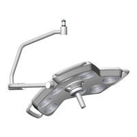
KLS Martin group marLED E15 Service Manual (192 pages)
Operating Lights
Brand:
KLS Martin group
| Category:
Medical Equipment
| Size: 46 MB
Table of Contents
Table of Contents
4
Notices Concerning this Document
9
Safety
9
Notices for Service Technicians
9
Terms & Acronyms
9
Validity of this Document
10
Other Applicable Documents
10
Symbols Used in this Document
10
Cable Colors
11
Product Liability and Warranty
11
General Information
11
Hotline
12
User's Inspection
12
Warranty
12
Intended Use
13
Intended Purpose
13
Safety Notices
15
General Information
15
Personal Protection
16
Screw Lock
18
Screw Torques
19
Greasing
19
Power Supply
20
Power Modules of Lights/Ceiling Tube Structure
20
Current SMPS Modules from HW 18
21
Available Power Module Versions
21
Circuit Diagram Without ASPS Assembly
22
Circuit Diagram with Integrated ASPS Assembly
23
Integrated ASPS Changeover Function (Optional)
24
Adjusting the Voltage
24
Power Supply Marled® E3 on Ceiling Tube Ø 110 MM
25
CAN Bus System/Rs232
27
CAT Wiring from HW 30
27
Cable Specifications
29
Pin Assignment According to TIA-568 B
29
Circuit Diagram, Video Cabling, CAN Bus Wiring
30
Light System with CAN Bus and 1 Ceiling Tube, no Galvanic Isolation
31
Standard CAN Board, no Galvanic Isolation
32
Terminating Resistor S1 Without Coupler
32
Pin Assignment of Cable Connection Terminal Block X3
33
CAN Board with Galvanic Isolation
34
Terminating Resistor S1 with Coupler
34
Light System with CAN Bus and 1 Ceiling Tube, with Galvanic Isolation
36
Connecting the Bus Couplers to the CAN Board
37
Connecting the Bus Couplers to the Power Supply
37
Bus Coupler Connection Board Pin Assignment
38
Troubleshooting on Bus Coupler
39
Coupler Block Diagram
40
Wall Box Connections (Rear)
40
Connecting the Wall Box to the Predecessor Wall Cable
41
Martouch® Wall Box Connections (Front)
41
Martouch® Wall Box Pin Assignment
42
COM Interface (RS232)
43
Connecting the COM Interfaces
43
COM Interfaces Marled® and Surgicam on Ceiling Tube from HW 37
44
COM Interfaces for Separate Installation HW 30 - HW 36
45
COM Interfaces for Separate Installation up to HW 09
46
Pin Assignment X2 (CAN, RS232)
47
CAN Bus Cabling up to HW 09
47
Overview of Camera System Surgicam HD, Cable and Connection Options
48
Addressing
49
DIP Switches for CAN Addresses and Terminating Resistors
49
DIP Switches SW6 for CAN Addresses and Configuration
49
DIP Switch SW1 Marled® for Terminating Resistor
50
DIP Switch SW1 Surgicam
51
CAN Address Setting from HW 30
51
Setting of the CAN Addresses up to HW 09
52
Central Bearing Shaft/Tracking Arm/Spring Arm Wiring
53
Central Bearing Shaft (Slip Rings)
53
Replacing the Contact Block
53
Checking the Voltage on Tracking Arm
54
Tracking Arm/Spring Arm from HW 30
57
Tracking Arm/Ceiling Tube
57
Circuit Diagram for 3-Pole Tracking Arm Marled® E9, E9I, E15 (Battery)
58
Circuit Diagram for 3-Pole Tracking Arm Marled® E3
58
Circuit Diagram for 5-Pole Tracking Arm with Wall Control Panel
58
Circuit Diagram for 9-Pole Tracking Arm with Wall Control Panel and Surgicam HD/SD
59
Tracking Arm/Spring Arm up to HW 09
62
Circuit Diagram for 5-Pole Tracking Arm with Wall Control Panel
62
Video Cabling
63
CAT from HW 30
63
Video Cabling to Monitor
64
Video Cabling to Wall Box
65
Cabling of the Wall Box Surgicam
66
Cabling of the NDS Scaleor with the Wall Boxes
67
Video Cabling to Monitor and then to Wall Box
68
Working on Light Head
70
Dismounting the Light Head
70
Adjusting the Height Stop on AC2000
71
Removing the Light Head from the Spring Arm
72
Reinstalling the Light Head on the Spring Arm
73
Light Head Overview
74
Service Plug
75
Preparatory Work on Light Head
76
Disconnecting the Battery Cable (Marled® E Battery)
77
Connecting the Battery Cable (Marled® E Battery)
77
Removing the Light Engine
78
Opening the Light Housing
79
Replacing the Gasket
81
Replacing the Battery Packs
81
Replacing the Control Panel Foil
84
Mounting and Connecting the Surgicam Daughterboard
86
Replacing the Control Electronics
87
Connectors for Light Engines
88
Connection Terminal for Supply Voltage/Can Bus
89
Connection for D-Sub Plug of Sensogrip
90
Replacing the Cardanic Suspension
91
Closing the Light Housing
94
Installing the Light Engines
96
Light Engine Variants
96
Installing the Light Engines
98
Wall Control Panel
99
Connecting a Wall Control Panel from HW 37
99
Connecting a Wall Control Panel HW 30 - HW 36
99
Connecting a Wall Control Panel up to HW 35
100
Parameter Menu for Switching between Modbus and Serial Control
102
Adjusting Parameter 0001
102
Activating and Verifying the Adjusted Parameter
103
Wall Control Panel Error Messages
104
Wall Control Panel and Surgicam Wiring up to HW 09
106
Description of Assemblies
107
Control Electronics Board
107
Design Including Miniature Fuses from HW 40
108
Design Including Miniature Fuses HW 32 - HW 39
109
Design Including Miniature Fuses up to HW 31
110
Light Engines
111
Light Engine Pin Assignment from HW 40
111
Light Engine Circuit Diagram from HW 40
111
Light Engine Pin Assignment up to HW 39
112
Light Engine Circuit Diagram up to HW 39
112
Cable Harness from Control Electronics Board to Light Engine of Marled® E9(I)
113
Cable Harness from Control Electronics Board to Light Engine of Marled® E15
113
Control Panel Foil
114
Description of the Control Panel Foil from HW 32
114
Additional Function Marled® E Battery
116
Description of the Control Panel Foil up to HW 31
118
Circuit Diagram of the Control Panel Foil from HW 32
118
Control Panel Foil Circuit Diagram for Marled® E Battery
120
Control Panel Foil Circuit Diagram up to HW 31
122
Programming
123
Marled® E Interface Adapter
123
Scope of Delivery
123
USB Serial Adapter
124
Software Update
125
Installing the C2Prog Programming Software on Your PC
125
Connecting the Interface Adapter
126
Programming Master
128
Programming Slave
129
Programming the Camera Daughterboard
131
Configuring the Light
132
Maintenance
133
Troubleshooting
133
Error Messages, Parameters
133
Error Patterns, Possible Causes and Corrective Actions
133
Identifying Master and Slave Channel
134
Inspection and Maintenance
135
Notices Concerning the Inspection
135
Notices Concerning the Inspection Plan
136
Inspection Plan
137
Test Instructions
141
Rating Plate and Serial Number
164
Serial Number Structure
165
Surgicam Serial Number
170
Spare Parts
171
Change History
171
Overview of Software Changes
171
Overview of Hardware Changes
177
Transport
182
Transport Regulations
182
Disposal
182
Packaging
182
Disposal of the Device
182
National Regulations
182
Technical Data
183
Technical Data for Marled® E9/E9I
183
Technical Data for Marled® E9/E9I Battery
185
Technical Data for Marled® E15
187
Technical Data for Marled® E15 Battery
189
Technical Data for Marled® E3
191
Advertisement
Advertisement
Related Products
KLS Martin group marLED E3
KLS Martin group marLED E9
KLS Martin group marLED E9i
KLS Martin group marLED V10
KLS Martin group marLED V16
KLS Martin group Laser Surgical Unit diomax 1550
KLS Martin group LIMAX 60
KLS Martin group Categories
Medical Equipment
Flashlight
Measuring Instruments
Outdoor Cart
Security Sensors
More KLS Martin group Manuals
Login
Sign In
OR
Sign in with Facebook
Sign in with Google
Upload manual
Upload from disk
Upload from URL