Sign In
Upload
Manuals
Brands
Johnson Controls Manuals
Controller
FMS-2000C
Johnson Controls FMS-2000C Manuals
Manuals and User Guides for Johnson Controls FMS-2000C. We have
2
Johnson Controls FMS-2000C manuals available for free PDF download: User Manual, Installation Manual
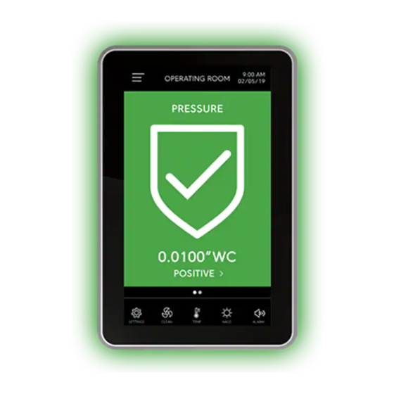
Johnson Controls FMS-2000C User Manual (62 pages)
Critical Environment Controller
Brand:
Johnson Controls
| Category:
Controller
| Size: 5 MB
Table of Contents
Table of Contents
6
Introduction
10
Display Overview
10
Initial Setup
14
Completing the Initial Setup
14
Configuration
15
Global Settings
15
Choosing a Unit of Measure
15
Choosing a Language
15
Choosing the Device Orientation
15
Switching on the 360° Safety Halo and Adjusting the Brightness of the 360° Safety Halo
15
Adjusting the 360° Safety Halo, Nightly Auto DIM and Dimmed Period
15
Adjusting the Screen Brightness
15
User Accounts
16
Admin User Capabilities
16
Restricted User Capabilities
16
User Name and Password Requirements
16
Creating the Admin User Account and Password
16
Creating a Restricted User and PIN Password
17
Deleting Users
17
Changing a User Name
17
Changing the Access Level of a Restricted User to an Admin User
17
Changing the Access Level of an Admin User to a Restricted User
17
Updating the PIN of a Restricted User
17
Forgetting Your Password or PIN
17
Network Setup
18
Bacnet MS/TP Network Setup
18
Setting up the Device ID Offset
18
Setting up the Maxmaster
18
Choosing the Baud Rate
18
Setting the MAC Address for Bacnet MS/TP
18
Metasys N2 Network Setup
19
Setting the Network Address for a Metasys N2 Network
19
Room Setup
20
Change the Isolation Mode for the Primary Monitored Space
20
Changing the Isolation Mode for the Secondary Monitored Space
20
Setting the Clean Duration for the Primary Monitored Space
20
Adjusting the Comfort Range for the Primary Monitored Space
20
Adjusting the Comfort Range for the Secondary Monitored Space
21
Analog I/O
22
Configuring Analog Inputs to Measure Pressure
23
Specifying the Parameter Type for Pressure
23
Specifying the Sensor Type
23
Specifying the Maximum Pressure Input
23
Specifying the Minimum Pressure Input
23
Specifying the K-Factor
24
Specifying the Sensor Location
24
Adjusting the Positive Isolation Setpoint
24
Adjusting the Negative Isolation Setpoint
24
Adjusting the Neutral Isolation Setpoint
24
Setting up the Analog Input Signal Range
24
Setting up the Sensor Range
25
Adjusting Deadband
25
Zero Calibration
25
Creating a Zero Offset
25
Resetting the Zero Offset
25
Setting the Alarms
25
Setting the Alarms for the First Time
26
Changing the Alarm Limits
26
Naming the Pressure Analog Input
26
Configuring the Analog Outputs to Control Pressure
27
Specifying the Operating Mode
27
Specifying the Output Range
27
Specifying the Action Mode
27
Mapping the Corresponding Analog Input Channel
27
Setting up Limits
27
Configuring Analog Inputs to Measure Temperature with a Thermistor
28
Setting up the NTC Type
28
Specifying the Occupied Setpoint
28
Specifying the Unoccupied Setpoint
28
Adjusting the Temperature Offset
28
Adjusting the Comfort Range
28
Adjusting the Alarm Settings
29
Naming the Thermistor Inputs
29
Configuring the Analog Input for Use with an External Thermostat
30
Configuring the Analog Input Type to an External Thermostat
30
Adjusting the Comfort Range for an External Thermostat
30
Naming an External Thermostat
30
Setting up the NTC Type for the Thermistor Inputs
30
Specifying the Occupied Setpoint for the Thermistor Inputs
30
Specifying the Unoccupied Setpoint for the Thermistor Inputs
30
Adjusting the Temperature Offset for the Thermistor Inputs
31
Adjusting the Comfort Range for the Thermistor Inputs
31
Adjusting the Alarm Settings for the Thermistor Inputs
31
Naming the Thermistor Inputs
31
Configuring the Analog Input for Temperature Measurement
31
Configuring the Analog Input Type for Precision Temperature
31
Specifying the Maximum Temperature Input
31
Specifying the Minimum Temperature Input
32
Specifying the K-Factor for Precision Temperature
32
Setting the Analog Output Signal Range for Precision Temperature
32
Adjusting the Setpoint for Precision Temperature
32
Adjusting the Alarm Settings for Precision Temperature
32
Naming Precision Temperature for the Analog Input
32
Configuring the Analog Output for Temperature Control
33
Setting up the Operating Mode for Temperature Control
33
Setting the Output Signal Range for Temperature Control
33
Setting up the Action Mode
33
Selecting the Corresponding Analog Input Channel
33
Setting up Limits
33
Configuring Analog Inputs to Measure Humidity
34
Configuring the Analog Input Type for Humidity
34
Specifying the K-Factor for Humidity
34
Setting the Setpoint to Zero for Humidity
34
Enabling the Alarm and Changing the Alarm Limits for Humidity
34
Naming the Humidity Input
34
Configuring the Analog Output for Humidity Control
35
Changing the Operating Mode for Humidity Control
35
Setting the Input Signal Range for Humidity
35
Specifying the Action Mode for Humidity
35
Selecting the Corresponding Analog Input Channel for Humidity
35
Setting up Limits for Humidity
35
Configuring the Analog Input to Measure Air Flow
36
Configuring the Analog Input Type to Measure Air Flow
36
Specifying the Sensor Type to Measure Air Flow
36
Specifying the Maximum Input Setting to Measure Air Flow
36
Specifying the Minimum Input Setting to Measure Air Flow
36
Setting up the Duct Area to Measure Air Flow
36
Specifying the K-Factor to Measure Air Flow
37
Calculating Air Changes Per Hour
37
Calculating the Room Volume for ACPH Measurement
37
Specifying the Output Signal Range for Air Flow
37
Adjusting Deadband for Air Flow
37
Enabling the Alarm and Changing the Alarm Limits for Air Flow
38
Naming the Air Flow Input
38
Configuring the Analog Inputs for Volumetric Offset Control
38
Configuring the Analog Output for Air Flow Control
38
Changing the Operating Mode for Air Flow Control
38
Setting the Input Signal Range for Air Flow Control
39
Specifying the Action Mode for Air Flow Control
39
Selecting the Corresponding Analog Input Channel for Air Flow Control
39
Setting up Limits for Air Flow Control
39
Configuring the Analog Input to Measure CO
39
Configuring the Analog Input Type to Measure CO
39
Specifying the Maximum CO Input
39
Specifying the Minimum CO Input
39
Specifying the K-Factor for CO
40
Enabling the Alarm and Changing the Alarm Limits for CO
40
Naming the CO Input
40
Configuring the Analog Output for CO Control
40
Changing the Operating Mode for CO Control
40
Setting the Signal Range for CO Control
40
Specifying the Action Mode for CO Control
41
Selecting the Corresponding Analog Input Channel for CO Control
41
Setting up Limits for CO Control
41
Digital Inputs
42
Configuring Digital Inputs for a Door Switch
42
Configuring the Switch Type
42
Setting up a Delay
42
Configuring Digital Inputs for an Override Switch Mode
42
Configuring the Switch Type
43
Setting up a Delay
43
Configuring Digital Inputs for Occupancy Switch Mode
43
Configuring Digital Inputs for Air Flow Switch Mode
43
Configuring the Switch Type
44
Setting up a Delay
44
Relays
45
Configuring the Trigger Mode for Setpoint
45
Configuring the Input Channel
45
Configuring the High and Low Setpoints
45
Configuring the Action Mode
46
Setting up a Delay
46
Configuring the Trigger Mode for Isolation Mode
46
Adjusting the Type of Isolation Mode
46
Configuring the Trigger Mode for Occupancy Mode
47
Adjusting the Occupancy Mode
47
Configuring the Action Mode
47
Setting up a Delay
47
Configuring the PID Loop
47
Setting up the Proportional Gain
47
Setting up the Integral Gain
47
Setting up the Derivative Constant
48
Home Screen Viewing Modes
49
Single View
49
Double View
50
Triple View
51
Quad View
51
Setting the Display for Single View Mode
52
Setting the Display to Double, Triple, or Quad Viewing Mode
52
Display
49
Switching on and Adjusting the Brightness of the 360° Safety Halo
49
Adjusting the 360° Safety Halo Nightly Auto DIM and Dimmed Period
49
Adjusting the Screen Brightness
49
Changing the Device Name
49
Alarms
53
Setting up Alarms for Analog Inputs
53
Diagnostics
53
Viewing the about this FMS Information
53
Accessing Real-Time View
53
Changing the Setpoints and Deadband from the Real-Time View
53
Adjusting the PID Loop for Analog Output 1 in Real-Time View
54
Adjusting the PID Loop for Analog Outputs 2, 3, and 4 in Real-Time View
54
Viewing Digital Inputs in Real-Time View
54
Viewing Relay Outputs in Real-Time View
54
Viewing the Alarm Status in Real-Time View
54
Overriding and Locking Analog Outputs
55
Unlocking the Overridden Analog Output
55
Setting the Actuator to Auto-Stroke
55
Overriding Relay Outputs
56
Saving Settings
56
Restoring Settings
56
Resetting the FMS-2000C Controller
56
Resetting the FMS-2000C
56
Restricted User Access
57
Changing the Time and Date
57
Adjusting the Alarm Mode
57
Setting the Audible Alarm Delay
57
Changing the Audible Alarm Snooze
57
Switching on and Adjusting the Brightness of the 360° Safety Halo
58
Adjusting the 360° Safety Halo Nightly Auto DIM and Dimmed Period
58
Setting the Night Mode
58
Adjusting the Temperature
58
Adjusting Screen Brightness
58
Changing the Isolation Mode for the Primary Space
58
Changing the Isolation Mode for the Secondary Space
58
Changing the Occupancy State for the Primary Space
59
Adjusting the Occupancy State for the Secondary Space
59
Quick Links
59
Activating and Deactivating the Cleaning Mode
59
Adjusting the Temperature Within the Comfort Range
59
Adjusting the 360° Safety Halo and Brightness
59
Adjusting the Nightly Auto DIM and Dimmed Period
59
Adjusting the Alarm Mode Quick Links
59
Adjusting the Isolation Mode Quick Link
59
Upgrading an Existing FMS-1655 Room Pressure Controller Display
60
Technical Specifications
61
Cleaning the Display
62
North American Emissions Compliance
62
Advertisement
Johnson Controls FMS-2000C Installation Manual (49 pages)
Critical Environment Controller
Brand:
Johnson Controls
| Category:
Controller
| Size: 15 MB
Table of Contents
Table of Contents
6
Introduction
7
Location Considerations
8
Mounting the FMS-2000C Display for a Retrofit Application
8
Mounting the FMS-2000C Display for a New Application
11
Mounting the Remote Sensor
13
Wiring Diagrams Guide
15
Wiring the FMS-2000C Controller Display to the FMS-2000C Controller
17
Retrofit of FMS-1655 Controller Display to FMS-2000C Controller Display
18
Wiring the Analog Output to a Pneumatic Damper Actuator
19
Wiring the Analog Output to a Variable Speed Drive
20
Wiring the Remote Sensor
21
Wiring the Analog Input to Remote Pressure Sensors
22
Wiring the Analog Input to Third-Party Sensor
25
Wiring the Analog Input for Temperature or Using a Thermistor
26
Wiring the Analog Input to a Room Thermostat
27
Wiring the Analog Input for Precision Temperature
28
Wiring the Digital Input to Door Switch
29
Wiring the Digital Input to Occupancy Sensor
30
Wiring the Relay Output to Alarm
31
Wiring the Relay Output to Warn
32
Wiring Relay Output 1
33
Wiring the Relay Output 2
34
Wiring Power
35
Wiring the Universal 120 V/240 V to 24 V Stepdown Isolation Transformer
36
Wiring the 24 V to 24 V Isolation Transformer
37
Wiring Communications to Bacnet MS/TP
38
Wiring Communications to Metasys N2 Open
39
Configuring Display Module Settings
40
Configuring Main Controller Module Settings
40
Configurations and Settings
41
Bacnet Objects
42
Metasys N2 Objects
45
Product Code Matrix
48
Cleaning the Display
49
North American Emissions Compliance
49
Advertisement
Related Products
Johnson Controls FMS-1655 Series
Johnson Controls FMS-1655L
Johnson Controls FX22 Series
Johnson Controls FX-PCV1610
Johnson Controls FX-PCV1826-1
Johnson Controls FA-33-741 Series
Johnson Controls F4-CGM09090-0
Johnson Controls F4-CGE09090-0H
Johnson Controls FAC36 Series
Johnson Controls FX-PCV1630
Johnson Controls Categories
Controller
Air Conditioner
Thermostat
Control Unit
Irrigation System
More Johnson Controls Manuals
Login
Sign In
OR
Sign in with Facebook
Sign in with Google
Upload manual
Upload from disk
Upload from URL