Sign In
Upload
Manuals
Brands
HEIDENHAIN Manuals
Control Panel
ITNC 530 - 6-2010 DIN-ISO PROGRAMMING
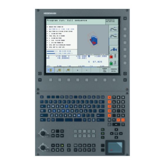
HEIDENHAIN ITNC 530 - 6-2010 DIN-ISO PROGRAMMING Manuals
Manuals and User Guides for HEIDENHAIN ITNC 530 - 6-2010 DIN-ISO PROGRAMMING. We have
1
HEIDENHAIN ITNC 530 - 6-2010 DIN-ISO PROGRAMMING manual available for free PDF download: User Manual
HEIDENHAIN ITNC 530 - 6-2010 DIN-ISO PROGRAMMING User Manual (618 pages)
DIN/ISO Programming
Brand:
HEIDENHAIN
| Category:
Control Panel
| Size: 22.92 MB
Table of Contents
About this Manual
5
Software Options
8
Legal Information
11
Table of Contents
19
1 First Steps with the Itnc 530
43
Machine Switch-On
43
Acknowledge the Power Interruption and Move to the Reference Points
43
Programming the First Part
44
The most Important Tnc Keys
44
Create a New Program/File Management
45
Define a Workpiece Blank
46
Program Layout
47
Program a Simple Contour
48
Create a Cycle Program
50
Select the Tool Table for the Test Run
52
Choose the Program You Want to Test
53
Select the Screen Layout and the View
53
Start the Program Test
54
Tool Setup
55
Prepare and Measure Tools
55
The Tool Table Tool.t
55
The Pocket Table Tool_P.tch
56
Workpiece Setup
57
Clamp the Workpiece
57
Align the Workpiece with a 3-D Touch Probe System
58
Set the Datum with a 3-D Touch Probe
59
Start the Program
60
Running the First Program
60
Choose the Program You Want to Run
60
2 Introduction
62
The Itnc
62
Programming: Heidenhain Conversational, Smart.nc and Iso Formats
62
Visual Display Unit
63
Sets the Screen Layout
64
Operating Panel
65
Operating Modes
66
Positioning with Manual Data Input
66
Manual Operation and Electronic Handwheel
66
Programming and Editing
67
Program Run, Full Sequence and Program Run, Single Block
68
Status Displays
69
General" Status Display
69
Additional Status Displays
71
Window Manager
79
Soft-Key Row
80
D Touch Probes
81
Hr Electronic Handwheels
82
Position Encoders and Reference Marks
84
Reference System
84
Reference System on Milling Machines
85
Polar Coordinates
86
Absolute and Incremental Workpiece Positions
87
Setting the Datum
88
3 Programming: Fundamentals, File Management
84
Creating and Writing Programs
89
Organization of an Nc Program in Din/Iso
89
Define the Blank: G30/G
89
Creating a New Part Program
90
Programming Tool Movements in Din/Iso Format
92
Actual Position Capture
93
Editing a Program
94
The Tnc Search Function
98
File Management
100
Data Backup
102
Show Externally Created Files on the Tnc
102
Working with the File Manager
103
Overview: Functions of the File Manager
104
Calling the File Manager
105
Selecting Drives, Directories and Files
106
Creating a New Directory (Only Possible on the Drive Tnc)
109
Creating a New File (Only Possible on the Drive Tnc)
109
Copying a Single File
110
Copying Files into Another Directory
111
Copying a Table
112
Choosing One of the Last Files Selected
113
Copying a Directory
113
Deleting a Directory
114
Deleting a File
114
Marking Files
115
Renaming a File
117
Additional Functions
118
Working with Shortcuts
120
Additional Tools for Management of External File Types
121
Data Transfer to or from an External Data Medium
125
The Tnc in a Network
127
Usb Devices on the Tnc (Fcl 2 Function)
128
4 Programming: Programming Aids
132
Adding Comments
132
Entering Comments During Programming
132
Inserting Comments after Program Entry
132
Entering a Comment in a Separate Block
132
Functions for Editing of the Comment
133
Structuring Programs
134
Definition and Applications
134
Displaying the Program Structure Window / Changing the Active Window
134
Inserting a Structuring Block in the (Left) Program Window
134
Selecting Blocks in the Program Structure Window
134
Integrated Pocket Calculator
135
Programming Graphics
136
Generating / Not Generating Graphics During Programming
136
Generating a Graphic for an Existing Program
136
Functions of the 3-D Line Graphics
138
Highlighting Nc Blocks in the Graphics
140
Display Help
141
Displaying Error Messages
141
Show Error List
142
Window Contents
143
Calling the Tncguide Help System
144
Generating Service Files
145
Working with the Tncguide
147
Table of Contents
148
Downloading Current Help Files
151
5 Programming: Tools
154
Entering Tool-Related Data
154
Feed Rate F
154
Spindle Speed S
155
Tool Data
156
Requirements for Tool Compensation
156
Tool Numbers and Tool Names
156
Tool Length L
156
Tool Radius R
156
Delta Values for Lengths and Radii
157
Entering Tool Data into the Program
157
Entering Tool Data in the Table
158
Tool-Carrier Kinematics
166
Using an External Pc to Overwrite Individual Tool Data
167
Pocket Table for Tool Changer
168
Calling Tool Data
171
Tool Change
173
Tool Usage Test
175
Tool Management (Software Option)
178
Introduction
182
Tool Compensation
182
Tool Length Compensation
182
Tool Radius Compensation
183
Programming: Programming Contours
187
Path Functions
188
Tool Movements
188
Miscellaneous Functions M
188
Subprograms and Program Section Repeats
188
Programming with Q Parameters
188
Programming Tool Movements for Workpiece Machining
189
Contour Approach and Departure
192
Starting Point and End Point
192
Tangential Approach and Departure
194
Overview of Path Functions
196
Inserting a Chamfer between Two Straight Lines
198
Corner Rounding G
199
Circle Center I, J
200
Circular Path C Around Circle Center CC
201
Circular Path G02/G03/G05 with Defined Radius
202
Circular Path G06 with Tangential Connection
204
Zero Point for Polar Coordinates: Pole I, J
210
Circular Path G12/G13/G15 Around Pole I, J
211
Circular Path G16 with Tangential Connection
212
Helical Interpolation
213
7 Programming: Data Transfer from DXF Files
219
Opening a Dxf File
219
Basic Settings
220
Layer Settings
222
Specifying the Reference Point
223
Selecting and Saving a Contour
225
Selecting and Storing Machining Positions
228
Zoom Function
234
Calling a Subprogram
238
Label G
239
Programming a Program Section Repeat
239
Calling a Program Section Repeat
239
Calling any Program as a Subprogram
240
Types of Nesting
242
Nesting Depth
242
Subprogram Within a Subprogram
243
Repeating Program Section Repeats
244
Repeating a Subprogram
245
Programming Examples
246
9 Programming: Q Parameters
254
Principle and Overview
254
Calling Q-Parameter Functions
257
Programming Fundamental Operations
260
Trigonometric Functions
261
Programming Trigonometric Functions
262
Unconditional Jumps
263
Programming If-Then Decisions
264
D14: Error: Displaying Error Messages
267
D15 Print: Output of Texts or Q Parameter Values
271
D19 Plc: Transfer Values to the Plc
272
Entering Formulas
273
Entering Formulas Directly
273
Rules for Formulas
275
Programming Example
276
String Parameters
277
String Processing Functions
277
Assigning String Parameters
278
Chain-Linking String Parameters
279
Converting a Numerical Value to a String Parameter
280
Copying a Substring from a String Parameter
281
Copying System Data to a String Parameter
282
Converting a String Parameter to a Numerical Value
284
Checking a String Parameter
285
Finding the Length of a String Parameter
286
Comparing Alphabetic Priority
287
Preassigned Q Parameters
288
Values from the Plc: Q100 to Q
288
Wmat Block: Qs
288
Active Tool Radius: Q
288
Tool Axis: Q
289
Spindle Status: Q
289
Coolant On/Off: Q
289
Overlap Factor: Q
289
Unit of Measurement for Dimensions in the Program: Q
290
Tool Length: Q
290
Coordinates after Probing During Program Run
290
Programming: Miscellaneous Functions
301
Programming Machine-Referenced Coordinates: M91/M
304
Activating the most Recently Entered Datum: M
306
Moving to Positions in a Non-Tilted Coordinate System with a Tilted Working Plane: M
306
Smoothing Corners: M
307
Insert Rounding Arc between Straight Lines: M
307
Machining Small Contour Steps: M
309
Machining Open Contours Corners: M
311
Feed Rate Factor for Plunging Movements: M
312
Feed Rate in Millimeters Per Spindle Revolution: M
313
Feed Rate for Circular Arcs: M109/M110/M
314
Calculating the Radius-Compensated Path in Advance (Look Ahead): M
315
Superimposing Handwheel Positioning During Program Run: M
317
Retraction from the Contour in the Tool-Axis Direction: M
318
Suppressing Touch Probe Monitoring: M
319
Delete Modal Program Information: M
320
Delete Basic Rotation: M
320
Automatically Retract Tool from the Contour at an Nc Stop: M
321
Suppress Limit Switch Message: M
322
Output the Programmed Voltage Directly: M
323
Output Voltage as a Function of Distance: M
323
Output Voltage as a Function of Speed: M
324
Programming: Special Functions
325
Overview of Special Functions
326
Main Menu for Spec Fct Special Functions
326
Program Defaults Menu
327
Functions for Contour and Point Machining Menu
327
Menu of Various Din/Iso Functions
328
Collision Monitoring in the Manual Operating Modes
331
Collision Monitoring in Automatic Operation
332
Graphic Depiction of the Protected Space (Fcl4 Function)
333
Collision Monitoring in the Test Run Mode of Operation
334
Fixture Templates
336
Setting Parameter Values for the Fixture: Fixturewizard
336
Placing the Fixture on the Machine
338
Editing Fixtures
339
Removing Fixtures
339
Check the Position of the Measured Fixture
340
Manage Fixtures
342
Tool-Holder Templates
344
Set the Tool Holder Parameters: Toolholderwizard
345
Removing a Tool Holder
346
Technical Prerequisites
349
Activating/Deactivating a Function
350
Basic Rotation
352
Swapping Axes
353
Superimposed Mirroring
354
Additional, Additive Datum Shift
354
Axis Locking
355
Superimposed Rotation
355
Feed Rate Override
355
Handwheel Superimposition
356
Defining the Afc Basic Settings
360
Recording a Teach-In Cut
362
Activating/Deactivating Afc
365
Log File
366
Tool Breakage/Tool Wear Monitoring
368
Spindle Load Monitoring
368
Creating Text Files
369
Opening and Exiting Text Files
369
Editing Texts
370
Deleting and Inserting Characters, Words and Lines
371
Editing Text Blocks
372
Finding Text Sections
373
Table for Workpiece Materials
375
Table for Tool Cutting Materials
376
Table for Cutting Data
376
Data Required for the Tool Table
377
Working with Automatic Speed / Feed Rate Calculation
378
Data Transfer from Cutting Data Tables
379
Configuration File Tnc.sys
379
Programming: Multiple Axis Machining
381
Define the Plane Function
385
Position Display
385
Reset the Plane Function
386
Defining the Machining Plane with Space Angles: Plane Spatial
387
Defining the Machining Plane with Projection Angles: Projected Plane
389
Defining the Machining Plane with Euler Angles: Euler Plane
391
Defining the Working Plane with Two Vectors: Vector Plane
393
Defining the Machining Plane Via Three Points: Plane Points
395
Defining the Machining Plane with a Single, Incremental Space Angle: Plane Relative
397
Tilting the Working Plane through Axis Angle: Plane Axial (Fcl 3 Function)
398
Specifying the Positioning Behavior of the Plane Function
400
Shorter-Path Traverse of Rotary Axes: M
407
Exact Stop at Corners with Nontangential Transitions: M
413
Selecting Tilting Axes: M
413
13 Programming: Pallet Editor
418
Pallet Editor
418
Selecting a Pallet Table
420
Pallet Datum Management with the Pallet Preset Table
421
Selecting a Pallet File
429
Setting up the Pallet File with the Entry Form
429
Sequence of Tool-Oriented Machining
434
14 Manual Operation and Setup
438
Switch-On, Switch-Off
438
Moving the Machine Axes
442
Incremental Jog Positioning
443
Traversing with Electronic Handwheels
444
MOD Functions
449
Entering Values
454
Changing the Spindle Speed and Feed Rate
455
General Information
456
Functional Safety Fs (Option)
456
Explanation of Terms
457
Check Axis Positions
458
Overview of Permitted Feed Rates and Speeds
459
Activating Feed-Rate Limitation
460
Workpiece Presetting with Axis Keys
462
Datum Management with the Preset Table
463
Using the 3-D Touch Probe
470
Selecting Probe Cycles
470
Writing the Measured Values from Touch Probe Cycles in Datum Tables
472
Writing the Measured Values from Touch Probe Cycles in the Preset Table
473
Storing Measured Values in the Pallet Preset Table
474
Calibrating a 3-D Touch Probe
475
Calibrating the Effective Length
475
Calibrating the Effective Radius and Compensating Center Misalignment
476
Displaying Calibration Values
477
Managing more than One Block of Calibrating Data
477
Basic Rotation Using 2 Points
480
Determining Basic Rotation Using 2 Holes/Studs
482
Workpiece Alignment Using 2 Points
483
Datum Setting in any Axis
484
Corner as Datum—Using Points that Were Already Probed for a Basic Rotation
485
Corner as Datum—Without Using Points that Were Already Probed for a Basic Rotation
485
Circle Center as Datum
486
Center Line as Datum
487
Setting Datum Points Using Holes/Cylindrical Studs
488
Measuring Workpieces with a 3-D Touch Probe
489
Using the Touch Probe Functions with Mechanical Probes or Dial Gauges
492
Traversing the Reference Points in Tilted Axes
495
Setting the Datum in a Tilted Coordinate System
495
Datum Setting on Machines with Rotary Tables
495
Datum Setting on Machines with Spindle-Head Changing Systems
496
Position Display in a Tilted System
496
Limitations on Working with the Tilting Function
496
Activating Manual Tilting
497
Setting the Current Tool-Axis Direction as the Active Machining Direction (Fcl 2 Function)
498
Positioning with Manual Data Input (MDI)
500
Protecting and Erasing Programs in $MDI
503
Plan View
508
Overview of Display Modes
508
Projection in 3 Planes
509
D View
510
Magnifying Details
513
Repeating Graphic Simulation
514
Displaying the Tool
514
Measuring the Machining Time
515
Functions for Program Display
516
Test Run
517
Program Run
523
Running a Part Program
524
Interrupting Machining
525
Moving the Machine Axes During an Interruption
527
Resuming Program Run after an Interruption
528
MID-Program Startup (Block Scan)
529
Returning to the Contour
532
Automatic Program Start
533
Optional Block Skip
534
Erasing the "/" Character
534
Changing the Settings
538
Selecting Mod Functions
538
Selecting the Mod Functions
538
Exiting the Mod Functions
538
Overview of Mod Functions
539
Software Numbers
540
Entering Code Numbers
541
Loading Service Packs
542
Setting the Data Interfaces
543
Setting the Rs-232 Interface
543
Setting the Rs-422 Interface
543
Setting the Operating Mode of the External Device
543
Setting the Baud Rate
543
Software for Data Transfer
545
Ethernet Interface
547
Connection Possibilities
547
Configuring the Tnc
547
Configuring Pgm Mgt
553
Changing the Pgm Mgt Setting
553
Dependent Files
554
Rotate the Entire Image
557
Position Display Types
558
Unit of Measurement
559
Working Without Additional Traverse Limits
562
Find and Enter the Maximum Traverse
562
Datum Display
563
Displaying Help Files
564
Selecting Help Files
564
Displaying Operating Times
565
Checking the Data Carrier
566
Performing the Data Carrier Check
566
Setting the System Time
567
Selecting Appropriate Settings
567
Calling/Exiting Teleservice
568
External Access
569
Setting the Transmission Channel
572
Selecting the Transmitter Power
573
Tables and Overviews
575
Overview
575
General User Parameters
576
Input Possibilities for Machine Parameters
576
Selecting General User Parameters
576
List of General User Parameters
577
Non-Heidenhain Devices
592
Rs-422/V.11 Interface
593
Ethernet Interface Rj45 Socket
593
Technical Information
594
Exchanging the Buffer Battery
603
Introduction
605
Operating Modes
606
Test Run
608
Status Displays
608
D Touch Probes
608
Overview Tables
609
Polar Coordinates
614
Files
615
Function
615
8 Programming: Subprograms and Program Section Repeats
616
Spindle Speed S
616
Function
616
Labels
616
Subprograms
616
Assignment
617
Advertisement
Advertisement
Related Products
Heidenhain 548431-05
HEIDENHAIN ND 522 - 2-2011
HEIDENHAIN ND 523 - 2-2011
HEIDENHAIN 547793-02
HEIDENHAIN 520010-01
HEIDENHAIN ITNC 530 - CYCLE PROGRAMMING
HEIDENHAIN ITNC 530 - PILOT SMART NC
HEIDENHAIN iTNC 530 E
HEIDENHAIN MANUALPLUS 4110
HEIDENHAIN ND 1100 - V2.15.0 GUIDE
HEIDENHAIN Categories
Media Converter
Measuring Instruments
Industrial Equipment
Control Systems
Controller
More HEIDENHAIN Manuals
Login
Sign In
OR
Sign in with Facebook
Sign in with Google
Upload manual
Upload from disk
Upload from URL