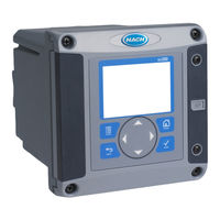
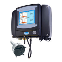
Sign In
Upload
Manuals
Brands
Hach Manuals
Controller
sc200
Hach sc200 Manuals
Manuals and User Guides for Hach sc200. We have
10
Hach sc200 manuals available for free PDF download: User Manual, Basic User Manual, Quick Manual, Software Update
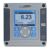
Hach sc200 User Manual (876 pages)
Brand:
Hach
| Category:
Controller
| Size: 27.96 MB
Table of Contents
Cleaning the Controller
1
Maintenance
1
Troubleshooting
1
Table of Contents
7
General Information
11
Specifications
11
Safety Information
12
Product Overview
13
Sensors and Sensor Modules
13
System Components
13
Controller Enclosure
14
Device Scans
14
Installation
14
Relays Outputs and Signals
14
Controller Mounting
15
Mounting Components
15
Surface Mounting Dimensions
15
Panel Mounting Dimensions
16
Pipe Mounting (Vertical Pipe)
16
Electrostatic Discharge (ESD) Considerations
17
High-Voltage Barrier
17
Top and Bottom Views
17
Wiring Overview
17
Wiring Connections Overview
18
Wiring for Power
19
Wiring Procedure
19
AC Power Wiring Information (AC Powered Models Only)
21
Alarms and Relays
21
DC Power Wiring Information (DC Powered Models Only)
21
Wiring Relays
21
Analog Output Connections
24
Discrete Input Wiring Connections
24
Input Connections
25
Jumper Settings
25
Connect a Digital Sc Sensor
26
Connect the Optional Digital Communication Output
26
Digital Sensor Quick Connect
26
Install a Secure Digital (SD) Memory Card
26
Display
27
Keypad and Front Panel Overview
27
User Interface and Navigation
27
Additional Display Formats
28
Example of Main Measurement Screen
28
Graphical Display
28
Icon Descriptions
28
Controller Configuration Information
29
Set the Language, Date and Time for the First Time
29
System Startup
29
Advanced Operation
30
Edit the Passcode
30
Enable or Disable the Passcode
30
Security Setup
30
Configure a 4-20 Ma Input Module
31
Configure a 4-20 Ma Output Module
31
Protect Features
31
Configure the Controller Analog Outputs
32
Bilinear Output Mode
34
Configure Relays
34
Logarithmic Output Mode
34
Scheduler Function
35
Alarm Function
36
Feeder Control Function
37
Event Control Function
38
Event Control Function (no Delay)
39
Event Control Function (Onmin Timer, Offmin Timer)
39
Event Control Function (ON/OFF Delay)
40
Pulse Width Modulation Control Function
40
Frequency Control Function
41
Pulse Width Modulation Function (Linear Mode)
41
Display Setup
42
Update the Date and Time
42
Warning Function
42
Set the Datalog Mode and Interval
43
Set up a Calculation
43
Set up the Discrete Inputs
43
Update the Display Language
44
Using the Secure Digital Memory (SD) Card
44
Saving Data and Event Logs with SD Cards
45
Updating Software
45
Access Data and Event Log Files on the SD Card
46
Backup Settings to an SD Card
46
Firmware Updates with SD Cards
46
Restore Settings to the Controller
47
Transfer Settings to Another Device
47
Using Datacom
47
Using the Service Port
47
Battery Replacement
48
Fuse Replacement
48
Maintenance
48
Test and Maintenance Menu
50
Warning and Error Conditions
51
Phd Sc Digital Differential Ph/Orp Sensors
55
Convertible Style Sensor Dimensions
62
Sensor Body Styles
62
Insertion Style Sensor Dimensions
63
Sanitary Style Sensor Dimensions
63
Stainless Steel Style Sensor (DPS1 and DRS5) Dimensions
63
Operating Precaution
64
The Digital Gateway
64
Attaching a Sc Sensor with a Quick-Connect Fitting
65
Connecting the Sc Sensor to a Sc100 Controller in a Non-Hazardous Location
65
Connecting/Wiring the Sensor to the Sc100 Controller
65
Attaching the Sensor Using the Quick-Connect Fitting
66
Hard-Wiring a Sc Sensor to the Controller
66
Connecting the Sc Sensor to a Sc100 Controller in a Hazardous Location
67
Hard-Wiring the Sensor
67
Wiring the Sensor at Terminal Block J5
67
Attaching a Sc Sensor with a Quick-Connect Fitting in a Hazardous Location
68
Connecting the Sensor to the Sc1000
68
Connecting the Sensor Using the Quick-Connect Fittings
68
Using the Digital Gateway
68
Proper Wire Preparation and Insertion
69
Wiring the Digital Gateway
69
Wiring and Assembling the Digital Gateway
70
Digital Gateway Dimensions
71
Mounting the Digital Gateway
71
Installing the Sensor in the Sample Stream
72
Sensor Installation Examples
72
Sensor Mounting Angle
73
Controller Key Functions/Features
75
Front of the Controller
75
Using the Sc100 Controller
75
Controller Display Features
76
Important Key Presses
76
Display Features
77
Using the Menu Windows
77
Using the Pop-Up Toolbar
77
Using the Sc1000 Controller
77
Navigating the Menu Windows
78
Changing a Menu Item
79
Keypad
79
List Box
80
Message Window
80
Operation
81
Sensor Data Logging
81
Sensor Diagnostics Menu for Ph and ORP Menu
81
Sensor Setup
81
ORP Sensor Setup Menu
83
One Point Manual Calibration
84
Ph Calibration
84
Two Point Automatic Calibration
84
ORP Calibration
85
Two Point Manual Calibration
85
Adjusting the Temperature
86
Concurrent Calibration of Two Sensors for Ph and ORP
86
Maintenance Schedule
87
Cleaning the Sensor
88
Replacing Standard Cell Solution and Salt Bridge
89
Replacing the Standard Cell Solution and Salt Bridge
89
Error Codes
91
Warning Codes
91
Warnings
91
Troubleshooting a Ph Sensor Without Integral Digital Electronics
92
Troubleshooting the Ph Sensor
92
Troubleshooting the Ph Sensor with Integral Digital Electronics
93
Checking ORP Sensor Operation
94
Troubleshooting the ORP Sensor with Integral Digital Electronics
94
Troubleshooting the ORP Sensor Without Integral Digital Electronics
94
Replacement Items, Accessories, and Reagent and Standards
95
Replacement Parts and Accessories
95
How to Order
97
General Ph Information
103
Ph Measurement Theory
103
PID Controller Basics
103
Modbus Register Information
107
Sensor Modbus Registers
107
Index
109
Differential Ph and ORP Sensors
111
Introducing the Modcon75 Controller
124
Overview
124
The Modcon75 System
124
Technical Description
125
Communications
126
Programming
126
HMI Application
127
PLC Application
127
Before Installation
128
Mounting
128
Vision Connectors and Mounting Brackets
128
Safety and Environmental Guideline
129
Earth Assembly
130
Modcon75 Controller Panel Cut-Out—Front View
130
Panel Mounted—Rear View
131
RS232 to RS422/RS485 Isolated Universal Converter
132
Top Connectors
133
Wiring Connections
133
Bottom Connectors
134
R-J11 Pin-Out
135
RS232 Wiring Considerations
135
RS485 Wiring Considerations
135
DIP Switch Settings
136
RS485 Terminal Wiring
136
Specifications of RS232 to RS485 Isolated Universal Controller
137
Mechanical Dimensions
138
Power Supply
139
Safety Considerations
139
Wiring the Power Supply
139
Earthing the Power Supply
140
Power Supply Wiring
140
I/O Modules
141
Installing a Snap-In I/O Module
141
Snap-In I/O Modules
141
Removing a Snap-In I/O Module
142
User Safety and Equipment Protection Guidelines
142
Environmental Considerations
143
Wiring
143
Digital Inputs
144
I/O Wiring—General
144
Wiring Procedures
144
Digital Inputs Used as Pnp (Source)
145
Digital Outputs
145
Relay Outputs
145
Wiring Power Supplies
145
Increasing Contact Life Span
146
Transistor Outputs
147
Snap-In I/O Module Technical Specifications
149
RS232 Port Printout
151
Operating Instructions
153
Power up Screen
153
Keypad Functions
154
Main Menu Screen
154
Add Units to Network
155
Password Entry
155
Add Units to the Network
156
Node Ids Found
157
Screen Displaying Node Ids Found
157
Add Unit Setpoints
158
Allows Users to Set Increasing or Decreasing Alarms
159
Allows Users to Set Latching / Non-Latching Alarms
159
Allows Users to Assign Zone Control Relays to Caution, Warning and Alarm Setpoints for Sensors 1, 2, and 3
160
Current Set-Point Values Read from the Selected Ultima X Unit
161
Sensor 1 Preset Screen
161
Sensor 2 Preset Screen
162
Sensor 3 Preset Screen
162
Displays All Presets before Downloading to the Unit
163
Verification Screen
164
All Clear Status Screen
165
Main Data Screen
165
Display Setpoints (View Only)
166
Password Editor
167
Modbus Alarms
168
Fault Status
169
Zone Editor
170
Zone Editor - Set Relays as Latched or Unlatched
170
Remote Relay Editor
171
Network Settings
172
Adjusting the LCD Screen Contrast
173
Labeling Keys
173
Operating Panel Options
173
Labeling Slides
174
Printing Customized Slides Using Templates
174
Removing and Inserting Slides
174
Modcon75 Specifications
175
Technical Specifications
175
Dimensions
176
Port 3 Ethernet Port / OPC Server
177
Critical Memory Bits
178
Memory Integers
178
Register Maps
178
Function Description – MI273 through MI297 – Signed Integer
185
Function Description – MI450 through MI474 – Signed Integer
186
Function Description – MI525 through MI599 – Signed Integer
186
Remote Relay Modules
187
Remote Relay Module Specifications
188
Power Supply, Pnp (Source) Inputs
190
JP1 Digital Inputs Type
191
JP2 Digital Inputs Voltage
191
JP3 Analog Input Type
191
JP5, JP6 Power Supply Voltage
191
Shown Jumper Settings
192
Opening the Controller Enclosure
193
Event Retrieval Tools
194
Installation Outline Wall Mount. Modcon 75
195
Contents
198
General Information
202
Ultima Calibrator
202
ADDRESS Button
203
At the Ultima Gas Monitor Display
203
CALIBRATE Button
203
Three Function Operation
203
ZERO Button
203
Setting up the Controller
204
The Ultima/Ultima X Controller (FIGURE 1-3)
204
To Disable the Password ID
205
To Enable or Change the Password ID
205
Turning the Controller on
205
Using the ID CODE Feature
205
Setting the Controller for an Ultima or Ultima X Series Instrument
206
Setting the Internal TIME of the Controller
206
Turning the Controller off
206
Note on Resetting Latched Alarms
207
Setting the Internal DATE of the Controller
207
When Sending a Command to the Ultima/Ultima X Series Gas Monitor
207
Chapter 2, Calibration
209
Equipment Required
209
Span Gas Values
210
Warning
210
Factory-Set Span Values
211
Calibration Kit 40 Contents
212
Calibration Kit 41 Contents
213
Calibration Kit 54 Contents
214
Calibration Guide for Combustible Gas Sensor
215
For Catalytic Type 1S General Solvents
216
For Ultima Ir Methane
216
For Ultima Ir Non-Methane
216
Ultima Xir Methane
217
Ultima Xir Non-Methane
217
Ultima/Ultima X Series Gas Monitor Calibration
217
Warning
217
INITIAL Calibration
218
Regular Calibration
219
Using the Zero Cap
219
Using Zero Gas Cylinder
219
Zeroing
219
Spanning
221
Span Set-Up (Ultima Unit Shown)
222
Span Gas Connection (Ultima Unit Shown)
223
Ultima X Series Unit Calibration End Display
223
OXYGEN Calibration
224
25% Oxygen Ultima/Ultima X Series Gas Monitor
225
Warning
225
XIR Calibration
225
Controller - Detailed Operation
226
The Controller Can Change the Display to Show
226
Viewing the Ultima Gas Monitor Display Modes
226
To View the Status of the Monitor
227
Procedure 1. Setting the Average Time Interval
228
Procedure 2. Setting the Span Value
228
Procedures (See TABLE 3-1)
228
To Change the Average Time Interval
228
To Change the Calibration Span Gas Value of the Ultima Sensor
228
To Change the Calibration Span Gas Value of the Ultima X Series Sensor
229
Procedure 3
230
Setting the Range on an Ultima X Series Sensor
230
Procedure 4
231
Setting the Gas Table for the Ultima XIR Sensor
231
Setting the Three Ultima Gas Monitor Alarm Setpoint Values
232
To Set the Three Levels of Alarm
232
Setting the Three Ultima X Series Gas Monitor Alarm Setpoint Values
233
To Set the Three Levels of Alarm
233
Enabling/Disabling and Setting the Mode of the Three Ultima Alarm Setpoints
234
Enabling/Disabling and Setting the Mode of Thethree Ultima X Series Alarm Setpoints
235
Procedure 6. Setting the Current Time
236
Procedure 7. Setting the Current Date
236
To Update the Ultima Gas Monitor Internal Clock
236
Enabling/Disabling Ultima Gas Monitor Calibration Output Signal
237
To Enable or Disable the Calibration Output Signal
237
To Update the Ultima Gas Monitor Internal Date
237
Setting the Number of Days between Ultima Gas Monitor Auto-Calibration Periods
238
Setting Time that Ultima Gas Monitor Auto-Calibration Is to Begin
238
Procedure 11. Changing the MUX Address
239
Setting the Date of the Next Scheduled Ultima Gas Monitor Calibration
239
Procedure 13. Calibrating/Checking the 4-20 Ma Ultima X Series Outputs
240
To Change the Address
240
Viewing the Previous Successful Calibration Date
240
Procedure 14. Resetting Ultima X Series Monitors
241
Alert Operation Settings
242
Setting the Alert Option on an Ultima X Series Sensor
242
Setting the Sensor Swap Delay on an Ultima X Sensor
242
Procedure 17
243
Setting an Unused Sensor to the Disabled Mode
243
Procedure 18. Setting the MODBUS BAUD Rate
244
Programming the Controller
244
Removing Existing Programs
244
Adding a New Program
245
To Use Programs 1 through 4
245
To Use Program #0
246
Determining a Low Battery Condition on the Ultima Controller
247
Maintenance
247
Replacing the Batteries
247
To Determine if Battery Replacement Is Necessary
247
To Install New Batteries in the Ultima Controller
247
Warning
247
Determining a Low Battery Condition on the Ultima Calibrator
248
To Install New Batteries in the Ultima Calibrator
248
Service
249
Troubleshooting Guidelines
249
Warning
249
Ultima X Series Gas Monitors
250
Gases
251
Installation Outline, Modbus, Ultima XE
256
Ultima X Gas Monitors with X Technology
260
Sensors
264
Transmitter Sensor Distance
264
Typical Modbus Network Topography
264
Maximum Power Cable Length
266
Remote Sensor Power Consumption (AC or DC Operation)
266
Transmitter Power Consumption
266
Typical Communications Wiring Scheme
267
Signal-Boost Sensor Diagram
268
Typical Communication Cable Wiring for Signal Boost
269
Typical Communication Cable Wiring for Signal Boost Option
270
Sensor Display Screens
271
Alarm Status Screen
272
Status Indication Codes
273
Ultima X Controller or Ultima X Calibrator
274
Modbus Communications
275
Push-Button Wiring
275
Modbus
276
Modbus Addressing
276
Supported Modbus Function Codes
276
Modbus Bas Address (Read/Write)
277
Modbus Base Address (Read/Write)
277
Modbus Memory Map Overview
277
Modbus Factory Configuration Data (Read Only)
278
Modbus User Configuration Data (Read/Write)
279
Alarm Function Codes
280
Modbus Fault Status Bits
283
Modbus General Status Bits
283
Control Words (Read/Write)
284
Odbus Command Word 1
284
Modbus Command Word 2
285
Sensor Type
285
Sensor Engineering Units
286
Information Flags Word #1
287
Information Flags Word #2
287
Information Flags Word #3
288
Information Flags Word #4
288
Alternate Gas Readings
289
Ft Simpson WWTP Upgrade
290
Getting Started
297
Connector Locations
298
Programming Cable Wiring
298
Alarms
299
Power Requirements
299
Protalk Plus Wiring Diagram
299
Expanders
300
Local Acknowledge
300
Radio
300
Telephone
300
Power-Up Sequence
301
Start-Up Programming
301
Site ID and Voice Alarm Messages
302
Telephone Numbers
303
Acknowledge Code
304
Front Panel
305
Protalk Plus Front Panel
305
Ptt
306
Ring
306
Acknowledging an Alarm
307
Alarm Sequence
307
Telephoning the B1290
307
Changing Telephone Directories
308
Error Messages
308
Program Summary
309
How to Enter the Programming Mode
310
Program Codes
310
Record Site ID and Alarm Messages
310
Directories
311
Erase All Messages
311
Record Relay Messages
311
Change this Line
313
Delete this Line
313
Insert a New Line
313
Access Code
314
DTMF Codes
314
Relay On/Off Input Codes
314
Alarm On/Off Output Codes
315
Directory Control Code
315
Interrogate Code
315
Remote Alarm Input Codes
315
Cycles through Timer a (Times A)
316
I/O Configuration
316
Interval Timer B
316
Rings before Answering
316
Alarm Delay (Debounce)
317
Alarm Format
317
Alarm Input Setup
317
Alarm Timer (Debounce) Timescale
317
Relay on Time
318
Relay Setup
318
Relay Timer Timescale
318
Using Directory
318
Acknowledge Request
319
Dial Format
319
Squelch Polarity
319
System Settings
319
Call Progress (Dial Tone Enable)
320
Number of Expanders
320
Site Voice Enable
320
Audio Levels
321
Reset Database
321
Alarm Announcement
323
Alarm Operation
323
Operation Codes
323
Programming Reference
323
Expander Attachment
324
Radio Specific Parameters
324
Telephone Specific Parameters
324
Programming Examples
325
Reporting Alarms over Radio and Telephone
325
Dialing from Two Different Telephone Directories
327
Different Alarms Dialing Different Telephone Numbers
329
Actuating Relays
330
Dialing a Paging Terminal
332
Operating a Radio Pager
332
Announcing Alarms over a Public Address System
333
Activating an Annunciator Panel
335
Concentrating Alarms from Remote Sites
335
Adding an Expander (B1292)
336
Concentrating Remote Alarms
336
I’ve Hooked up the B1290 as Per the Installation Instructions but Nothing Happens
338
The B1290 Does Not Dial out over the Telephone Line When an Alarm Occurs
338
The B1290 Waits a Long Time before Announcing the Alarm over the Radio
338
The B1290 will Not Program from a Local Programming Phone
338
Our Operators Live in an Area Which Has a Dial Pulse Exchange. How Can They Acknowledge the B1290 When It Calls?
339
The B1290 Does Not Activate Its Relay When I Send the DTMF on Code
339
The B1290 will Not Acknowledge
339
The B1290 Won’t Answer the Phone
339
How Can I Prevent Unauthorized Personnel from Calling up the B1290 and Altering Its Programming?
340
I Tried to Change the Telephone Numbers and Now the B1290 will Not Dial out at All
340
The B1290 Has Lost Its Programmin
340
Programmable Features
342
AC Adapter
344
Options
344
Programming Tree
345
Mounting Detail
348
Directory Summary
351
Hardware Summary
351
System Summary
351
The Eaton 9130 Rackmount EBM
361
The Eaton 9130 Rackmount UPS
361
The Eaton 9130 Tower UPS and EBM (2000–3000 VA Models Shown)
361
Safety Warnings
362
Inspecting the Equipment
376
Checking the Accessory Kit
377
Unpacking the Cabinet
377
Rackmount Installation
378
Assembling the Rails
379
Rackmount Setup
379
To Install the Rail Kit
379
Securing the Rails
380
Installing the Mounting Brackets (Forward Position Shown)
381
Securing the Front of the Cabinet
381
Installing the UPS
382
Rackmount Wiring Installation
382
Securing the Back of the Cabinet
382
Connect the Internal Battery Connector
383
Removing the UPS Right Front Cover
383
Connecting the UPS Internal Batteries
384
Connecting the EBM(S)
385
Removing the EBM Cable Knockout
385
Removing the EBM Front Cover
386
Typical EBM Installation
387
To Install the Cabinet
388
Tower Installation
388
Removing the UPS Front Cover
389
Tower Wiring Installation
389
UPS Initial Startup
393
Control Panel Functions
396
Eaton 9130 Control Panel
396
Changing the Language
397
Display Functions
397
Indicator Descriptions
397
Menu Map for Display Functions
398
User Settings
399
Battery Mode
402
Normal Mode
402
Operating Modes
402
Bypass Mode
403
Standby Mode
404
Starting the UPS
404
UPS Startup and Shutdown
404
Starting the UPS on Battery
405
Retrieving the Event Log
406
Transferring the UPS between Modes
406
UPS Shutdown
406
Configuring Bypass Settings
407
Setting Power Strategy
407
Configuring Load Segments
408
To Set the Restart and Shutdown Delay Times for each Load Segment
409
Configuring Battery Settings
410
Configuring the UPS for Ebms
410
Configuring Automatic Restart
411
For Automatic Battery Tests to Run
411
Running Automatic Battery Tests
411
Communication
412
Communication Options and Control Terminals
412
Communication Options
413
Installing Communication Options and Control Terminals
413
RS-232 and USB Communication Ports
413
RS-232 Communication Port (DB-9 Connector)
414
RS-232 Communication Port Pin Assignment
414
Connectivity Cards
415
Remote Emergency Power-Off
415
REPO Connections
416
Relay Output Configuration Options
417
Relay Output Contacts
417
Standard Relay Port Connections
417
Polarity Options
418
Programmable Signal Inputs
418
Lansafe Power Management Software
419
Modem Operation
419
UPS and Battery Care
420
UPS Maintenance
420
Replacing Batteries
421
Storing the UPS and Batteries
421
When to Replace Batteries
421
Replacing Rackmount UPS Internal Batteries
422
Disconnecting the UPS Internal Batteries (Shown Without Ebms)
423
Replacing Tower UPS Internal Batteries
425
To Replace the Batteries in the UPS
425
Replacing the UPS Internal Batteries
426
Replacing Rackmount Ebms
428
Replacing Tower Ebms
430
Testing New Batteries
431
Recycling the Used Battery or UPS
432
Updating the UPS Firmware
432
Extended Battery Module Model List
434
Model Specifications
434
UPS Model List (Rackmount Models)
435
UPS Model List (Tower Models)
436
Weights and Dimensions (Rackmount Models)
437
Electrical Input (Rackmount Models)
439
Electrical Input (Tower Models)
440
Electrical Input Connections (Rackmount Models)
441
Electrical Input Connections (Tower Models)
442
Electrical Output (All Models)
443
Electrical Output Connections (Rackmount Models)
444
Electrical Output Connections (Tower Models)
445
Environmental and Safety (All Models)
446
Battery Runtimes (in Minutes) at 100% Load (Rack Models)
447
Battery Runtimes (in Minutes) at 100% Load (Tower Models)
448
Battery
449
Rear Panels
450
Typical Alarms and Conditions
460
To Check the Event Log for a History of Conditions
461
Service and Support
464
Silencing the Alarm
464
Isolating Switching Amplifier 2-Channel IM1-22X-R
470
Solahd STV 25 K DIN Rail Series Instruction Manual
474
Applying Power
475
DIN Rail Mounting
475
Voltage Ratings & Power Source Configurations
475
RV042 and RV042G Ports
513
Rv0Xx Series Router Features
513
RV016 Ports and Status Lights
514
RV042 and RV042G Status Lights
514
RV082 Ports and Status Lights
514
Default Settings
516
Other Hardware Features
516
Desktop Placement
517
Mounting Options
517
Placement Tips
517
Wall Mounting
517
Rack Mounting RV082 or RV016
518
Connecting the Equipment
519
Getting Started with the Configuration
520
Troubleshooting Tips
521
LED Indicators
530
Typical LED Location
530
Recommended DIN Rail Mounting Steps
532
Mechanical Dimensions for SL-2/3/5/6/8/9ES-1/2/3 in Lexan Packaging
536
Mechanical Dimensions for SLX-2/3/5/6/8/9ES-1/2/3 in Metal Packaging
536
Mechanical Dimensions for SL/SLX-5/8MS-1/4/5 with up to 2 Fiber Ports
537
Mechanical Dimensions for SL/SLX-5MS-MDM-1
537
Mechanical Dimensions for SL/SLX-8ES-6/7 with 3 Fiber Ports
538
Mechanical Dimensions for SL/SLX-8MS-8/9 with 4 Fiber Ports
538
Mechanical Dimensions for SL/SLX-8MG with 8 Gigabit Ports
539
Mechanical Dimensions for SLX-10MG-1
539
Mechanical Dimensions for SLX-16MS-1
540
Mechanical Dimensions for SLX-18MG-1
540
Notes and Recommendations for Best Heat Dissipation
541
Overview of Optional Mounting Methods
541
Power and Output Wiring
542
Power & Alarm Wiring for SL/SLX-5/8MS Managed Switches
543
Power Wiring for SL/SLX-5/8/9ES Unmanaged Switches and SL-2ES Media Converter
543
Power & Alarm Wiring for SL/SLX-8MG Managed Switches
544
Power & PLC Wiring for SL/SLX-5MS-MDM Ethernet Modem
544
Power and Alarm Wiring for SL/SLX-6ES Unmanaged Switches
545
Power and Alarm Wiring for SLX-10/16/18-MX Managed Switches
545
Communication Ports Wiring
546
Cross-Over Cable Wiring
546
Ethernet Plug & Connector Pin Positions
546
Straight-Thru Cable Wiring
546
Telephone Ports on Modem Models
548
Serial Console Port Wiring
549
USB Console Port Wiring
549
Service Information
554
Broad Range of Application
564
Easy Maintenance
564
High Performance
564
Rugged ‘‘Long-Life’’ Construction
564
Heat Losses
565
Model Selection
565
Number of Units
565
Spot Heating
565
Steam Capacities
566
Vertical Projection
567
Btu Correction Factors
568
Design Conditions
568
Selecting a Unit Heater for Use with Steam
568
Selection Procedure
568
Air Density Ratio
569
Air Distribution Correction Factors
569
Noise Level Classes
569
Horizontal Projection
570
Hot Water Capacities
570
Hot Water Correction Factors
574
Selecting a Unit Heater for Use with Hot Water
574
Motor Characteristics
575
Typical Wiring Diagram
575
Unit Heater Motor Speeds & Switches
575
Casing
577
Coil
577
Diffusers
577
Guide Specifications
577
3100, 3900, 4000 and 4100 Series Control Dampers
580
MACH-Propoint
608
MACH-Pro Websys
610
Driverx VFD Cable
638
Drilling Template
661
Model 6 Motor Control Centers
673
Figure 1: Model 6 MCC 100 Ms Arc-Rated Option Label and Typical Location on Enclosure
682
Table 1: MCC-Related Literature
683
Table 2: IMCC-Related Literature
684
Figure 2: Motor Control Center Packaged in Sideways Position (Typical for most Sections)
686
Figure 3: Motor Control Center Packaged in Upright Position (Typical for Extra Heavy Sections such as 18-Pulse Drives or as Customer Option)
686
Table 3: Approximate MCC Shipping Weights
687
Figure 4: Moving the MCC with a Fork Truck
688
Figure 5: Proper Use of Sling to Lift Mccs
688
Figure 6: Proper/Improper Lifting Points for Plug-In Units Taller than 24 in
689
Figure 7: Required Obstruction-Free Area
691
Figure 8: Motor Control Center Views
692
Figure 10: Hardware Kit
693
Figure 9: Base Channel Notches
693
Figure 11: Bolting Sections Together
694
Figure 12: Standard Base Channel Mounting
695
Figure 13: Base Channel Mounting for 18-Pulse AC Drive MCC Sections
695
Figure 14: NEMA Type 1, Type 1 Gasketed, and Type 12 Seismic Tie-Down Locations
697
Figure 15: Seismic Tie-Down Locations for 18-Pulse AC Drive MCC Sections
697
Figure 16: NEMA Type 3R Seismic Tie-Down Locations
698
Figure 17: Attachment Locations for Top Lateral Bracing
699
Figure 18: P Gasketing
700
Figure 19: Removing the End Deflector
702
Figure 20: Removing the Insulating Barrier
703
Figure 21: Installing the Deflector Bracket
703
Figure 22: Re-Attaching the Back Plates
704
Figure 23: Installing the Splice Deflector
705
Figure 24: Remove MID and End Deflector Caps from the Top of the MCC
706
Figure 25: Attach the Multi-Section Bracket
706
Figure 26: Secure the Vertical Channels
706
Figure 27: Replace Lifting Angle Hardware
706
Figure 28: Horizontal Wireway Covers and Bus Barriers Removed
707
Figure 29: Correct Application of Splice (Shown Installed) for 600/800 A, Non-Fork Bus
708
Figure 30: Incorrect Application of Single-Bar Splice on Fork-Type Bus
708
Figure 31: Removing Bolts from Single-Splice Bar
708
Figure 32: Moving and Aligning the Splice Bar to the Bus Holes
709
Figure 33: Inserting Splice Bolts in the Left and Right Sections
709
Figure 34: Placing a Conical Washer under the Bolt Head
709
Figure 35: Torquing the Bolts
709
Figure 36: Removing the Left Bolts and Loosening the Right Bolts on the Splice Assembly
710
Figure 37: Aligning the Splice and Bus Holes
710
Figure 38: Inserting the Splice Bolts
711
Figure 39: Placing a Conical Washer under the Bolt Head
711
Figure 40: Torquing the Bolts
711
Figure 41: Wireway Covers Removed and Horizontal Bus Barriers Open
712
Figure 42: Loosen Bolts
712
Figure 43: 85,000 a Bracing Option
712
Figure 44: Slide the Splice Assembly to the Left
713
Figure 45: Inserting the Splice Bolts
713
Figure 46: Place a Conical Washer under the Bolt Head
713
Figure 47: Torque All Bolts
713
Figure 48: Ground Splice Bar as Shipped
714
Figure 49: Ground Bar Bolt Replaced
714
Figure 50: Wireway Covers Removed and Horizontal Bus Barriers Open
715
Figure 51: Removing the Bolts from the Splice Assembly
715
Figure 52: Aligning the Splice and Bus Holes
715
Figure 53: Inserting the Splice Bolts
715
Figure 54: Place a Conical Washer under the Bolt Head
715
Figure 55: Torque All Bolts
716
Figure 56: Splicing Offset Horizontal Bus
717
Figure 57: Remove the Hardware
718
Figure 58: Reposition and Attach the Vent Hood
719
Figure 59: Remove the Hardware
720
Figure 60: Install the Pull Box
720
Vented Pull Box Installation for Mccs with 2500 a Horizontal Bus
720
Figure 61: Wiring in the Top Horizontal Wire Trough
721
Figure 62: Vertical Wire Trough Grommet
721
Figure 63: Pull-Apart Type Terminal Blocks
721
Load and Control Wiring
721
Crimp Lug Cable Assembly for Cabled Disconnect Unit Installation
722
Figure 64: Typical Cabled Disconnect Unit
722
Figure 65: Typical Horizontal Bus Assembly
722
Cable Connection Torque Values
723
Component Instructional Information
723
Figure 66: Main Lug Compartment Torque Connection
723
Table 4: Connection Torque Values for Main Lug Compartments
723
Table 5: Connection Torque Values for Main and Branch Feeders
723
Figure 67: Size 1 and 2 Fuse Clip Locations
724
Modifying Fuse Clip Locations
724
Figure 68: Pre-Operation Check
725
Pre-Operation Checklist
725
Section 5-Operation
725
Energizing the MCC
726
Examining the Enclosure
727
Figure 69: Typical Bus Connection Points
727
Maintaining Bus Bars and Incoming Line Compartments
727
Section 6-Maintaining the MCC
727
Table 6: Bus Connection Torque Values
727
Figure 70: Main Lug Compartment Torque Connection
728
Figure 71: Control Unit
728
Maintaining the Control Unit
728
Figure 72: Operator Mechanism in the off Position
729
Figure 73: Loosening Captive Fasteners
729
Figure 74: Arc-Rated MCC Door Latches
729
Removing the Control Unit
729
Figure 75: Releasing the Lock-In Device (When Supplied)
730
Figure 76: Disconnected Terminal Blocks
730
Figure 77: Power Leads and Top of Terminal Blocks Fed through Wiring Port
730
Figure 78: Pulling the Twin Handle Cam Mechanism Forward
730
Figure 79: Operating the Mechanism-To-Structure Interlock
731
Figure 80: Locked out Device
731
Figure 81: Control Unit Removed
731
Figure 82: Control Unit with Bottom Plate Folded down
731
Figure 83: Driving out Hinge Pin
732
Removing the Compac™ 6 Control Unit
732
Figure 84: Operator Handle in the off Position
733
Figure 85: Loosening Captive Fasteners
733
Figure 86: Control Station Plate Removed
733
Figure 87: Operator Handle and Interlock Release
734
Figure 88: Stab Assembly
734
Tests and Maintenance Performed with the Control Unit Removed
734
Figure 89: Operator Mechanism in the Tripped Position
735
Figure 90: Inspecting Fuses
735
Figure 91: Starter Contacts
735
Figure 92: Control Devices
736
Figure 93: Tripping the Overload Relay
736
Figure 94: Tightening Electrical Connections
736
Figure 95: Manual and Automatic Bus Shutters
737
Reassembly
737
Insulation Test
738
Maintenance after a Fault Has Occurred
739
Figure 96: Typical Bus Connection Points
740
Figure 97: Operating Door Interlock Defeat Mechanism
740
Table 7: Bus Connection Torque Values
740
Figure 100: NEMA Rated Standard Unit
741
Figure 98: Motor Logic SSOLR
741
Figure 99: NEMA Rated Compac™ 6 Unit
741
Section 7-Motor Logic Solid-State Overload Relay (SSOLR)
741
Motor Logic Retrofit Applications
742
Figure 101: Looping Passes
743
Figure 102: Motor Logic Overload (Bottom View)
743
Table 8: Lug Types and Wire Sizes
743
Figure 103: Unit Adjustment Label
744
Unit Adjustment Label
744
Adjusting Mag-Gard or Powerpact Magnetic Trip Setting
745
Figure 104: Mag-Gard Magnetic Trip Adjustment
745
Section 8-Mag-Gard™ and Powerpact™ Motor Circuit Protector Settings
745
Figure 105: Powerpact H- and J-Frame Magnetic Trip Adjustment
746
Figure 106: Powerpact L-Frame Instantaneous Trip Adjustment
746
Figure 107: Powerpact P-Frame Instantaneous Trip Adjustment
746
IMCC Overview
747
Networks/Communications Overview
747
Section 9-IMCC
747
Bridges/Repeaters
748
Cables between Shipping Splits
748
Communication Networks
748
Connecting the IMCC Cabling System
748
Direct Cable Connection
748
Load Cables
748
Table 10: Network Connection Pin Outs
748
Table 9: Pin Outs for IMCC Networks
748
Terminating Resistors
748
Figure 108: Typical Cabling Scheme for Modbus ® Two-Wire
749
Figure 109: Typical Cabling Scheme for Devicenet™ and Canopen (8A Cable)
750
Figure 110: Typical Cabling Scheme for PROFIBUS
751
MCC Structure
752
Pre-Operation Checklists
752
Cabling Connections
753
Communications Setup
753
Energizing the MCC
753
IMCC Communications
753
Figure 111: Motor Logic Plus Communication Module Terminals
754
Motor Logic Plus Local Programming
754
Motor Logic Plus Remote Programming
755
Table 11: Local Error Display
755
Table 12: Command Line Codes
755
Table 13: Motor Logic Plus Address Descriptions
756
Table 14: Read-Only Registers
757
Table 15: Read/Write Registers
758
Figure 112: Tesys T Controllers
759
Figure 113: NEMA Rated Control Unit (Tesys T Modbus)
759
Tesys T Motor Management Controller
759
Applications Requiring Turns
760
Tesys T Retrofit Applications
760
Configuring with HMI
761
Tesys T Local Programming
761
Altistart 48
762
Altivar™ 61/71
762
Configuring with Powersuite Software
762
Powerlogic Circuit Monitor
762
Powerlogic™ Power Meter Series 800
762
Device Addressing
763
Powerpact Circuit Breakers with Micrologic Trip Units
763
Software
763
Figure 114: Typical Arc-Rated Label Locations on Sections and Units
764
Ordering Information
764
Section 10-Expansion
764
De-Energizing Equipment and Identifying Unit Type
765
Modifying MCC Units
765
Modifying Removable Units
765
Modifying Fixed Units
766
Figure 115: Shelf and Door Installation
767
Figure 116: Midshelf for Arc-Rated Mccs
767
Installing Additional MCC Units
767
Table 16: Shelf Installation Kit Parts
767
Figure 117: Cutting the Vertical Wire Trough Grommet (When Supplied)
768
Figure 118: Removing the Manual Bus Shutter
768
Figure 119: Engaging the Cam Mechanism
768
Figure 120: Handles Flush with the Front of the MCC
768
Compac 6 Units
769
Figure 121: Tightening the Control Unit Lock-In Panel (When Supplied)
769
Figure 122: Power Leads Connected to Power Terminals
769
Figure 123: Connecting Control Leads to the Terminal Blocks
769
Cable Connection Torque Values
770
Control and Load Wiring
770
Figure 124: Pull-Apart Terminals
770
Figure 125: Typical Unit Torque Label
770
Figure 126: Fuse Bases
770
Compac 6 Control Unit Installation
771
Figure 127: Reinstalling the Compac 6 Control Unit
771
Section 11-Troubleshooting
772
Table 17: Motor Control Center Troubleshooting Chart
773
Section 12-Insulation Resistance
776
Thermal Overload Unit Selection
777
Size 5 with CT Type Overloads and Circuit Breakers
778
Size 5 with CT Type Overloads and Fusible Switch Disconnects
778
Size 5 Without CT Type Overloads
778
Melting Alloy Overload Selection Tables for Part Winding Combination Starter Units
779
Ambient-Compensated Bimetallic Overload Selection Tables for Combination Starter Units
781
Ambient-Compensated Bimetallic Overload Selection Tables for Part Winding Combination Starter Units
782
Figure 128: Circuit Breaker Replacement
783
Section 13-Circuit Breaker and Fusible Switch Replacement
783
Section 14-Installation and Maintenance Log
784
Advertisement
Hach sc200 Basic User Manual (662 pages)
Brand:
Hach
| Category:
Controller
| Size: 4.4 MB
Table of Contents
Table of Contents
2
English
4
Specifications
4
General Information
4
Installation
7
User Interface and Navigation
22
Details
22
System Startup
25
Maintenance
26
Troubleshooting
26
Deutsch
30
Italiano
57
Italiano
58
Français
84
Español
111
Português 137
137
Čeština 163
163
Dansk 189
189
Nederlands 215
215
Polski
242
Svenska
268
Suomi
294
Български 319
319
Magyar
346
Română 373
373
Lietuvių Kalba
400
Türkçe 455
455
Slovenský Jazyk
480
Slovenski
506
Hrvatski 531
531
Ελληνικά
556
Eesti Keel 583
583
Српски 609
609
Hach sc200 Basic User Manual (210 pages)
Brand:
Hach
| Category:
Controller
| Size: 3.12 MB
Table of Contents
Table of Contents
2
English 3
3
Français
28
Español
56
Português 83
83
日本語
134
ไทย
184
Advertisement
Hach sc200 User Manual (146 pages)
Conductivity Module
Brand:
Hach
| Category:
Controller
| Size: 1.41 MB
Table of Contents
Table of Contents
2
English 3
3
Deutsch 9
9
Italiano
16
Français
22
Español
28
Português
34
Čeština
40
Dansk
46
Nederlands
52
Polski
58
Svenska 65
65
Suomi 71
71
Български 77
77
Magyar 83
83
Română 89
89
Lietuvių Kalba 95
95
Русский 101
101
Türkçe
108
Slovenský Jazyk
114
Slovenski
120
Hrvatski
126
Ελληνικά
132
Eesti Keel 139
139
Hach sc200 User Manual (56 pages)
Brand:
Hach
| Category:
Controller
| Size: 2.09 MB
Table of Contents
Table of Contents
3
Specifications
5
General Information
5
Safety Information
6
Use of Hazard Information
6
Precautionary Labels
6
Certification
6
Product Overview
7
Sensors and Sensor Modules
8
Relays Outputs and Signals
8
Device Scans
8
Controller Enclosure
8
Controller Mounting Options
8
Installation
9
Mounting Components and Dimensions
9
Controller Mounting
10
High-Voltage Barrier
13
Electrostatic Discharge (ESD) Considerations
13
Wiring Overview
14
Wiring for Power
14
Alarms and Relays
17
Wiring Relays
17
Analog Output Connections
19
Discrete Input Wiring Connections
20
Connect a Digital Sc Sensor
22
Connect the Optional Digital Communication Output
23
Install a Secure Digital (SD) Memory Card
23
User Interface and Navigation
24
User Interface
24
Display
24
Additional Display Formats
25
Graphical Display
25
System Startup
26
Set the Language, Date and Time for the First Time
26
Controller Configuration Information
26
Advanced Operation
27
Security Setup
27
Enable or Disable the Passcode
27
Edit the Passcode
27
Protect Features
28
Configure a 4-20 Ma Input Module
28
Configure a 4-20 Ma Output Module
29
Configure the Controller Analog Outputs
29
Logarithmic Output Mode
31
Bilinear Output Mode
31
Configure Relays
32
Display Setup
41
Update the Date and Time
42
Set the Datalog Mode and Interval
42
Set up a Calculation
42
Set up the Discrete Inputs
43
Update the Display Language
44
Using the Secure Digital Memory (SD) Card
44
Updating Software
44
Saving Data and Event Logs with SD Cards
45
Access Data and Event Log Files on the SD Card
45
Firmware Updates with SD Cards
46
Backup Settings to an SD Card
46
Restore Settings to the Controller
46
Transfer Settings to Another Device
47
Using the Service Port
47
Using Datacom
47
Hach sc200 User Manual (42 pages)
Brand:
Hach
| Category:
Controller
| Size: 1.93 MB
Table of Contents
Table of Contents
3
Specifications
5
General Information
5
Expanded Manual Version
5
Safety Information
6
Use of Hazard Information
6
Precautionary Labels
6
Hach Certification of Compliance
6
Product Overview
7
Installation
8
Mounting Components and Dimensions
8
Controller Mounting
9
High-Voltage Barrier
10
Electrostatic Discharge (ESD) Considerations
11
Wiring Overview
11
Wiring for Power
13
Alarms and Relays
15
Wiring Relays
15
Analog Output Connections
17
Connect a Digital Sc Sensor
18
Connect the Optional Digital Communication Output
18
Install a Secure Digital (SD) Memory Card
18
User Interface and Navigation
19
User Interface
19
Display
19
System Startup
20
Set the Language, Date and Time for the First Time
20
Adjust the Display Contrast
21
Controller Configuration Information
21
Advanced Operations
22
Security Setup
22
Enable or Disable the Passcode
22
Edit the Passcode
22
Configure a 4-20 Ma Input Module
22
Configure a 4-20 Ma Output Module
23
Configure the Controller Analog Outputs
23
Logarithmic Output Mode
25
Bilinear Output Mode
25
Configure Relays
26
Relay Function Graphs
28
Set up a Calculation
33
Set the Datalog Mode and Interval
33
Using the Secure Digital Memory (SD) Card
33
Saving Data and Event Logs with SD Cards
34
Access Data and Event Log Files on the SD Card
35
Firmware Updates with SD Cards
35
Using the Service Port
35
Using Datacom
35
Update the Display Language
36
Update the Date and Time
36
Hach sc200 User Manual (52 pages)
Conductivity Module
Brand:
Hach
| Category:
Control Unit
| Size: 1.27 MB
Table of Contents
Table of Contents
2
English 3
3
Français 9
9
Español 15
15
Português 21
21
日本語 33
33
Hach sc200 User Manual (44 pages)
Flow Module
Brand:
Hach
| Category:
Control Unit
| Size: 2.07 MB
Table of Contents
Table of Contents
2
English 3
3
Français
8
Español 13
13
Português
18
日本語
28
ไทย
38
Hach sc200 Quick Manual (2 pages)
Brand:
Hach
| Category:
Measuring Instruments
| Size: 0.88 MB
Hach sc200 Software Update (2 pages)
Brand:
Hach
| Category:
Controller
| Size: 0.17 MB
Advertisement
Related Products
Hach sc1000
Hach sc100
Hach SC1500
Hach SC4200c
Hach SC4500
Hach sc100 1720E
hach sc200 4-20
Hach si792 E
Hach sensION+ DL
Hach SIP 10 kit
Hach Categories
Measuring Instruments
Laboratory Equipment
Accessories
Controller
Control Unit
More Hach Manuals
Login
Sign In
OR
Sign in with Facebook
Sign in with Google
Upload manual
Upload from disk
Upload from URL