Hach sc200 User Manual
Hide thumbs
Also See for sc200:
- User manual (876 pages) ,
- Basic user manual (662 pages) ,
- Software update (2 pages)
Table of Contents
Advertisement
Advertisement
Table of Contents

Related Manuals for Hach sc200


Summary of Contents for Hach sc200
- Page 1 DOC023.53.80040 sc200 Controller 03/2010, Edition 1 User Manual...
-
Page 3: Table Of Contents
General Information ..................................3 Expanded manual version .................................3 Safety information ..................................4 Use of hazard information ..............................4 Precautionary labels ...................................4 Hach certification of compliance ............................4 Product overview ..................................5 Installation ......................................6 Mounting components and dimensions .............................6 Controller mounting ...................................7 High-voltage barrier ...................................8 Electrostatic discharge (ESD) considerations ...........................9 Wiring overview ....................................9... - Page 4 Table of Contents Advanced operations ................................20 Security setup ....................................20 Enable or disable the passcode ...............................20 Edit the passcode ..................................20 Configure a 4-20 mA input module ..............................20 Configure a 4-20 mA output module ...............................21 Configure the controller analog outputs ............................21 Logarithmic output mode ................................23 Bilinear output mode ..................................23 Configure relays ....................................24 Relay function graphs ................................26...
-
Page 5: Specifications
Four SPDT, user-configured contacts, rated 5A 250 VAC (resistive). Contacts are rated 250 VAC, 5 Amp Specifications are subject to change without notice. resistive maximum for the AC powered sc200 and 24 VDC, 5A resistive maximum for the DC powered Component description Microprocessor-controlled and menu-driven sc200. -
Page 6: Safety Information
W A R N I N G Hach certification of compliance Indicates a potentially or imminently hazardous situation which, if not avoided, could result in death or serious injury. -
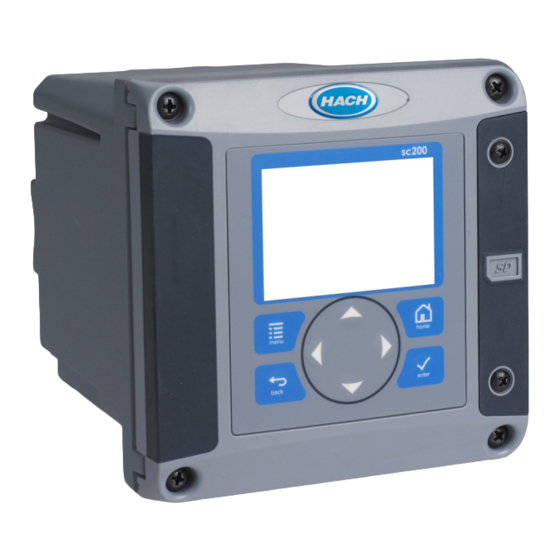
Page 7: Product Overview
These limits are designed to provide reasonable protection against Figure 1 System components harmful interference when the equipment is operated in a commercial environment. This equipment generates, uses, and can radiate radio frequency energy and, if not installed and used in accordance with the instruction manual, may cause harmful interference to radio communications. -
Page 8: Installation
The controller has four configurable relay switches and two analog For both horizontal and vertical pipe mounts, attach the mounting bracket outputs. An optional analog output module can increase the number of to the controller as shown in Figure 6 on page 8. -
Page 9: Controller Mounting
Controller mounting Figure 3 Controller dimensions Figure 4 Panel mount English 7... -
Page 10: High-Voltage Barrier
Figure 5 Wall mount Figure 6 Pipe mount (vertical pipe) High-voltage barrier High-voltage wiring for the controller is located behind the high-voltage barrier in the controller enclosure. The barrier must remain in place except when installing modules or when a qualified installation technician is wiring 8 English... -
Page 11: Electrostatic Discharge (Esd) Considerations
for power, alarms, outputs or relays. Do not remove the barrier while power from your body. This can be accomplished by touching an earth- is applied to the controller. grounded metal surface such as the chassis of an instrument, or a metal conduit or pipe. - Page 12 Figure 7 Wiring connections overview 1 Service cable connection 4 Communication module connector (e.g., Modbus, 7 Relay connections Profibus, optional 4-20 mA module, etc.) 2 4-20 mA output 5 AC and DC power connector 8 Digital sensor connector 3 Sensor module connector 6 Ground terminals 9 Digital sensor connector 10 English...
-
Page 13: Wiring For Power
The controller can be wired for line power by hard-wiring in conduit or Wiring for power wiring to a power cord. Regardless of the wire used, the connections are W A R N I N G made at the same terminals. A local disconnect designed to meet local electrical code is required and must be identified for all types of installation. - Page 14 12 English...
-
Page 15: Alarms And Relays
Table 1 AC power wiring information (AC powered models only) W A R N I N G Wire color code Terminal Wire color code Potential fire hazard. Do not daisy-chain the common relay connections Terminal number for North description for Europe or jumper wire from the mains power connection inside the instrument. - Page 16 14 English...
-
Page 17: Analog Output Connections
• Use of non-shielded cable may result in radio frequency emission Analog output connections or susceptibility levels higher than allowed. W A R N I N G • Maximum loop resistance is 500 ohm. 5. Close the controller cover and tighten the cover screws. Potential Electrocution Hazard. -
Page 18: Connect A Digital Sc Sensor
When a sensor is connected with the controller powered on, the controller lange.com or http://www.hach.com. does not automatically perform a device scan. To make the controller perform a device scan, navigate to the Test/Maintenance menu and select Install a Secure Digital (SD) memory card Scan Devices. -
Page 19: User Interface And Navigation
User interface and navigation Inputs and outputs are set up and configured through the front panel using the keypad and display screen. This user interface is used to set up and configure inputs and outputs, create log information and calculated values, User interface and calibrate sensors. -
Page 20: System Startup
Warning icons Figure 12 Example of Main Measurement screen A warning icon consists of an exclamation point within a triangle. Warning icons appear in the display footer along with a number that indicates the associated device. • 0=controller • 1=sensor 1 •... -
Page 21: Adjust The Display Contrast
2. Select an option and push ENTER to activate the menu item. on the CD. 1. To navigate to the menu options, from the Settings Menu, select sc200 Setup. English 19... -
Page 22: Advanced Operations
The passcode is enabled. This information will be used to set the display range. 5. Push the BACK key to return to the sc200 Setup Menu, or push the 4. From the Settings Menu, select Sensor Setup. MENU key to return to the Settings Menu. -
Page 23: Configure A 4-20 Ma Output Module
The Network Setup option appears in the Settings Menu only if an analog 1. From the Settings menu, select sc200 Setup. output module or other network module such as Modbus or Profibus is installed in the controller. - Page 24 5. From the Output Setup menu, choose Select Parameter and choose Option Description an option from the list. Parameters will vary depending on the type of Set mode (Auto Auto—the signal is automatically controlled by the algorithm sensors installed. or Manual) within the analyzer using proportional, integral, and 6.
-
Page 25: Logarithmic Output Mode
Figure 13 Logarithmic output Option Description Set low value Sets the low endpoint value of the process variable range. Set high value Sets the high endpoint value of the process variable range. Set knee point value Sets the value at which the process variable range divides into another linear segment. -
Page 26: Configure Relays
For more information about the Fail 8. From the Relay Setup menu, select Activation. Safe option, refer to sc200 Setup. To select a menu option, highlight the The activation options for the selected function appear. Use the option and push ENTER. - Page 27 9. Test the relay function to make sure it is properly energizing the Option Description connected device. Relay testing is performed through the Test/Maint High Sets the range where the relay remains on after the measured option of the Settings menu. deadband value decreases below the high alarm value.
-
Page 28: Relay Function Graphs
Option Description Option Description Deadband Sets a hysteresis so the relay will not swing unregulated when Set mode Auto—The relay works as a PID controller. the process value converges to the setpoint Manual—the relay output has an On/Off ratio as set in the Manual Output menu. - Page 29 Figure 15 Alarm mode Figure 16 Feeder control mode 1 High alarm 5 ON delay 2 High deadband 6 OFF delay 3 Low deadband 7 Time (x-axis) 1 Deadband (Phase = Low) 6 Time (x-axis) 4 Low alarm 8 Source (y-axis) 2 Deadband (Phase = High) 7 ON delay (phase set high) 3 setpoint...
- Page 30 Figure 17 Feeder control mode (Phase low, Overfeed timer) Figure 18 Event control mode (no delay) 1 Deadband 5 ON delay 2 setpoint 6 OFF delay 1 High alarm 4 OnMax-time 3 Overfeed timer 7 Source (y-axis) 2 Low alarm 5 OffMax-time 4 Time (x-axis) 3 Time (x-axis)
- Page 31 Figure 19 Event control mode (OnMin timer, OffMin timer) Figure 20 Event control mode (ON/OFF delay) 1 High alarm 4 OFF delay 1 High alarm 5 OnMin timer 2 Low alarm 5 Time (x-axis) 2 Low alarm 6 OffMin timer 3 ON delay 6 Source (y-axis) 3 OffMin timer...
- Page 32 Figure 21 Pulse Width Modulation control (linear mode) Figure 22 Frequency control mode 1 High alarm 4 Time (x-axis) 1 High limit 4 Cycle duration 2 Low alarm 5 Selected source (y-axis) 2 Low limit 5 Selected source (y-axis) 3 Period 3 Time (x-axis) 30 English...
-
Page 33: Set Up A Calculation
Datalog Setup is available if a calculation has been set up. 2 OFF delay 4 Time (x-axis) 1. From the Settings menu, select sc200 Setup and push ENTER. Set up a calculation 2. Select Datalog Setup and push ENTER. 3. Select Set Mode and push ENTER. -
Page 34: Saving Data And Event Logs With Sd Cards
The DataCom manual, software updates and other • Data and event logs can be downloaded to an SD card and viewed with downloadable resources are available at http://www.hach.com/ any device capable of reading an SD card. download-resources. • Data logs store the measurement data at selected intervals in a packed binary format (.flg file). -
Page 35: Access Data And Event Log Files On The Sd Card
Event logs have the following structure: Device Name, Device Serial device. Number, Device Identification, Event Log, Time Stamp. 2. In the directory of the SD card, open the HACH folder. To view data or event log files stored on the SD card: 3. Select the Firmware folder. -
Page 36: Update The Display Language
Use the right and left arrow keys to highlight a field. to be a service activity. If a blown fuse is suspected, contact Hach b. Use the up and down arrow keys to change the values in the field Technical Support. -
Page 37: Troubleshooting
Fat 32 format. The MMC format is not not recognized by the controller supported. Follow the instructions of the card Contact Hach Technical Support. manufacturer to format the SD card on a PC. Verify current output configuration. Make sure the card is not larger than 32 GB. -
Page 38: Test And Maintenance Menu
Resolution Make sure an appropriate folder is created by If the sensor is an analog sensor and a installing the SD card in the sc200. An update corresponding module is installed in the folder will automatically be created. controller, refer to the instructions supplied with the Network or Sensor Module. -
Page 39: Warning And Error Conditions
Reset default config Resets controller configuration settings to default Note: Errors cannot be acknowledged. values 5. For more information on a specific warning, error or event, refer to the Restart sc200 Performs a controller restart device manual. Simulation (only Source-... -
Page 40: Replacement Parts And Accessories
SD card reader LZY522 • Push the left arrow key to select or de-select a missing device. SD card cover for sc200 controller 8787100 • Push the Enter key to delete the missing device. Spare screws for controller installation kit... - Page 42 © Hach Company, 2010. All rights reserved. Printed in the U.S.A.
Need help?
Do you have a question about the sc200 and is the answer not in the manual?
Questions and answers