Sign In
Upload
Manuals
Brands
FLIR Manuals
Thermographic Cameras
ThermaCAM P20
User Manuals: FLIR ThermaCAM P20 Thermal Imaging Camera
Manuals and User Guides for FLIR ThermaCAM P20 Thermal Imaging Camera. We have
1
FLIR ThermaCAM P20 Thermal Imaging Camera manual available for free PDF download: Operator's Manual
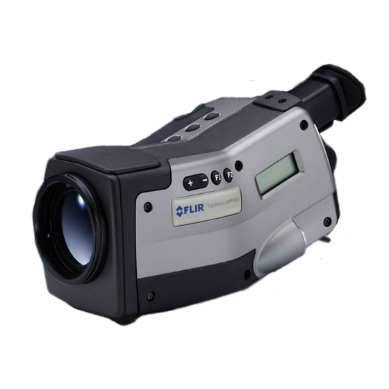
FLIR ThermaCAM P20 Operator's Manual (142 pages)
camera
Brand:
FLIR
| Category:
Thermographic Cameras
| Size: 8 MB
Table of Contents
Table of Contents
5
1 Warnings & Cautions
13
2 Welcome
14
About FLIR Systems
14
Figure 2.1 FLIR Systems, Boston, USA, FLIR Systems, Danderyd, Sweden, and FLIR Systems, Portland, USA
15
A few Images from Our Facilities
16
Figure 2.2 LEFT: FLIR Systems' Thermovision ® Model 661. the Photo Is Taken on May 30Th
16
Figure 2.3 LEFT: Development of System Electronics; RIGHT: Testing of an FPA Detector
16
Comments & Questions
17
Figure 2.4 LEFT: Diamond Turning Machine; RIGHT: Lens Polishing
17
Figure 2.5 LEFT: Testing of IR Cameras in the Climatic Chamber; RIGHT: Robot for Camera Testing and Calibration
17
3 Packing List
19
4 System Overview
20
Figure 4.1 System Overview
20
5 Connecting System Components
21
Figure 5.1 How to Connect System Components, 1: Rear Connectors
21
Figure 5.2 Explanations of Callouts
21
Figure 5.3 How to Connect System Components, 1: Front Connectors
22
Figure 5.4 Explanations of Callouts
22
6 Tutorials
23
Switching on & Switching off the Camera
23
Working with Images
23
Acquiring an Image
23
Opening an Image
23
Freezing & Unfreezing an Image
24
Saving an Image
24
Creating & Changing an Isotherm
24
Changing Level & Span
25
Changing the Level
25
Changing the Span
25
Changing System Settings
25
Changing the Language
25
Changing the Temperature Unit
26
Changing the Date Format
26
Changing the Time Format
26
Changing Date & Time
27
Working with the Camera
27
Mounting an Additional Lens
27
Figure 6.1 Mounting an Additional Lens
27
Focusing the Camera Using Autofocus
28
Focusing the Camera Manually
28
Using the Electronic Zoom
28
Inserting & Removing the Battery
28
Inserting the Battery
28
Figure 6.2 Inserting the Battery
28
Removing the Battery
29
Figure 6.3 Removing the Battery
29
7 Installation & Operation of Thermacam Connect
30
Introduction
30
Installation
30
Software Requirements
30
Camera
30
Installing Thermacam Connect 3
31
Installing Drivers
31
USB Driver Installation Procedure for Microsoft Windows XP
31
USB Driver Installation Procedure for Microsoft Windows 2000
32
USB Driver Installation Procedure for Microsoft Windows ME
33
USB Driver Installation Procedure for Microsoft Windows 98
34
Operation
34
Transferring the Images from the Camera to the Computer
34
Transferring All Images from the Internal Camera Memory
35
Figure 7.1 Image Transfer Application
35
Figure 7.2 Image Transfer
36
Transferring a Selection of Images or Images from Another Folder
37
Figure 7.3 Browse for Images
37
Program Options
38
Figure 7.4 Options
38
Auto Detect
39
How to Connect
39
Figure 7.5 RS-232 Options
39
How to Disconnect
40
Starting Transfer Application
40
Figure 7.6 Transfer Application
40
Support
41
Information
41
Troubleshooting
41
General
41
Figure 7.7 Starting the Transfer Application from Windows Start Menu
41
Problems When Trying to Communicate with the Camera
42
Problems When Connecting the IR Camera Using USB
42
Bus) or Firewire
42
Problems When Connecting the IR Camera Using Serial Communication
43
Camera Icon Not Visible on System Tray
43
8 Camera Overview
44
Camera Parts
44
Figure 8.1 Camera Parts
44
Figure 8.2 Camera Parts
45
Figure 8.3 Camera Parts
47
Keypad Buttons & Functions
48
Autofocus
48
Figure 8.4 Camera Buttons - Explanations
48
Camera Status LCD
49
Figure 8.5 Camera Status LCD
49
Figure 8.6 Camera Status LCD - Explanations
49
9 Camera Program
51
Screen Objects
51
Result Table
51
Status Bar
51
Temperature Scale
51
Figure 9.1 Explanation of Measurement Markers Appearing in the Result Table
51
Figure 9.2 Status Bar, Showing Atmospheric Temperature, Relative Humidity, Distance to Target
51
Figure 9.3 Temperature Scale
51
System Messages
52
Status Messages
52
Warning Messages
52
Menu System
52
Navigating in the Menu System
52
Figure 9.4 Status Messages - a few Examples
52
Figure 9.5 Critical Camera Information - a few Examples
52
File Menu
53
Open
53
Save
53
Directories
53
Figure 9.6 File Menu
53
Figure 9.7 Open Dialog Box
53
Figure 9.8 Directories Dialog Box
53
Delete Image
54
Analysis Menu
54
Edit Mode
54
Add Isotherm
54
Figure 9.9 Delete Image Dialog Box
54
Figure 9.10 Analysis Menu
54
Figure 9.11 Temperature Scale Showing an Isotherm Set to above +62 °C
55
Figure 9.12 Shortcut Menu for Isotherm
55
Figure 9.13 Explanations of the Isotherm Shortcut Menu
55
Figure 9.14 Isotherm Dialog Box
56
Figure 9.15 Explanations of the Isotherm Dialog Box
56
Remove All
57
Obj Par
57
Deactivate Local Par
57
Figure 9.16 Object Parameters Dialog Box
57
Image Menu
58
Freeze/Live
58
Range
58
Level/Span
58
Figure 9.17 Image Menu
58
Figure 9.18 Range Dialog Box
58
Figure 9.19 Symbols in the Temperature Scale, Indicating (1) Increasing Span; (2) Decreasing
58
Manual Adjust / Continuous Adjust
59
Palette
59
Hide Graphics
59
Figure 9.20 Palette Dialog Box
59
Figure 9.21 Explanations of the Palette Dialog Box
59
Setup Menu
60
Image
60
Figure 9.22 Setup Menu
60
Figure 9.23 Image Setup Dialog Box
60
Figure 9.24 Explanations of the Image Setup Dialog Box
60
Save
61
Figure 9.25 Save Setup Dialog Box
61
Figure 9.26 Explanations of the Save Setup Dialog Box
61
Figure 9.27 Naming Based on Unique Counter - Explanations
62
Figure 9.28 Naming Based on Current Date - Explanations
62
Figure 9.29 Naming Based on Current Directory - Explanations
62
Power
63
Figure 9.30 Power Setup Dialog Box
63
Figure 9.31 Explanations of the Power Setup Dialog Box
63
Status Bar
64
Figure 9.32 Status Bar Dialog Box
64
Figure 9.33 Explanations of the Status Bar Dialog Box
64
Date/Time
65
Local Settings
65
Figure 9.34 Date/Time Dialog Box
65
Figure 9.35 Explanations of the Date/Time Dialog Box
65
Figure 9.36 Local Settings Dialog Box
65
Camera Info
66
Factory Default
66
Figure 9.37 Explanations of the Local Settings Dialog Box
66
10 Electrical Power System
67
Internal Battery Charging
67
External Battery Charging
68
Figure 10.1 Stand-Alone Battery Charger
68
Figure 10.2 LED Indicators on the Stand-Alone Battery Charger
68
Figure 10.3 LED Indicators - Explanations
68
Battery Safety Warnings
69
11 Note on LEMO Connectors
71
How to Connect & Disconnect LEMO Connectors
71
Figure 11.1 Straight Body LEMO Connector
71
Figure 11.2 Unlocking a LEMO Connector
72
12 Maintenance & Cleaning
73
Camera Body, Cables & Accessories
73
Lenses
73
13 Troubleshooting
74
14 Technical Specifications & Dimensional Drawings
77
Imaging Performance
77
Detector
77
Image Presentation
77
Temperature Ranges
78
Electrical Power System
78
Environmental Specifications
78
Physical Specifications
79
Interfaces & Connectors
79
Pin Configurations
79
RS-232/USB Connector
79
Figure 14.1 Pin Configuration for RS-232/USB Connector (on Camera - Operator's Side)
79
Power Connector
80
CVBS Connector
80
Figure 14.2 Pin Configuration for Power Connector (on Camera - Operator's Side). A: Center Pin
80
Figure 14.3 Pin Configuration for CVBS Connector (on Camera - Operator's Side). A: Center Pin
80
Relationship between Fields of View and Distance
81
Figure 14.4 Relationship between Fields of View and Distance. 1: Distance to Target; 2: VFOV
81
Figure 14.5 Horizontal, Vertical and Instantaneous Fields of View for Certain Distances to Targets
81
Figure 14.6 F-Number and Close Focus Limits for Various Lenses
83
Basic Dimensions - Battery Charger
84
Figure 14.7 Overall Dimensions of the Battery Charger
84
Basic Dimensions - Battery
85
Figure 14.8 Overall Dimensions of the Battery
85
Basic Dimensions - Camera (1)
86
Figure 14.9 Overall Dimensions of the Camera
86
Basic Dimensions - Camera (2)
87
Figure 14.10 Location of the Standard Tripod Mount (1/4"-20) on the Bottom Side of the Camera
87
15 Glossary
88
Figure 15.1 Glossary of Common Infrared Terms & Expressions
88
16 Thermographic Measurement Techniques
92
Introduction
92
Emissivity
92
Finding the Emissivity of an Object
93
Using a Thermocouple
93
Using Reference Emissivity
93
Reflected Ambient Temperature
93
Distance
93
Relative Humidity
93
Other Parameters
93
17 History of Infrared Technology
95
Figure 17.1 Sir William Herschel (1738-1822)
95
Figure 17.2 Marsilio Landriani
96
Figure 17.3 Macedonio Melloni
97
Figure 17.4 Samuel
97
18 Theory of Thermography
99
Introduction
99
The Electromagnetic Spectrum
99
Figure 18.1 the Electromagnetic Spectrum. 1: X-Ray; 2: UV; 3: Visible; 4: IR; 5: Microwaves; 6: Radiowaves
99
Blackbody Radiation
100
Figure 18.2 Gustav Robert Kirchhoff
100
Figure 18.3 Max Planck (1858-1947)
101
Planck's Law
101
Figure 18.4 Blackbody Spectral Radiant Emittance According to Planck's Law, Plotted for Various Absolute Temperatures. 1: Spectral Radiant Emittance
102
Wien's Displacement Law
102
Figure 18.5 Wilhelm Wien
103
Figure 18.6 Planckian Curves Plotted on Semi-Log Scales from 100 K to 1000 K. the Dotted Line
104
Stefan-Boltzmann's Law
104
Figure 18.7 Josef Stefan (1835-1893), and Ludwig Boltzmann
105
Non-Blackbody Emitters
105
Infrared Semi-Transparent Materials
107
Figure 18.8 Spectral Radiant Emittance of Three Types of Radiators. 1: Spectral Radiant Emittance; 2: Wavelength; 3: Blackbody; 4: Selective Radiator; 5: Graybody
107
Figure 18.9 Spectral Emissivity of Three Types of Radiators. 1: Spectral Emissivity; 2: Wavelength; 3: Blackbody; 4: Graybody; 5: Selective Radiator
107
19 The Measurement Formula
109
Figure 19.1 a Schematic Representation of the General Thermographic Measurement Situation.1
109
Surroundings; 2: Object; 3: Atmosphere; 4: Camera
109
Figure 19.2 Voltages
111
Figure 19.3 Relative Magnitudes of Radiation Sources under Varying Measurement Conditions (SW Camera). 1: Object Temperature; 2: Emittance; RED: Object Radiation; BLUE
113
C (+68 °F); T = 20 °C (+68 °F)
113
Figure 19.4 Relative Magnitudes of Radiation Sources under Varying Measurement Conditions (LW Camera). 1: Object Temperature; 2: Emittance; RED: Object Radiation; BLUE
113
20 Emissivity Tables
114
References
114
Tables
114
Figure 20.1 T: Total Spectrum; SW: 2-5 ΜM; LW: 8-14 ΜM, LLW: 6.5-20 ΜM; 1: Material; 2: Specification; 3: Temperature in °C; 4: Spectrum; 5: Emissivity: 6: Reference
114
Index
131
Advertisement
Advertisement
Related Products
FLIR ThermaCAM P65
FLIR ThermaCAM P65 HS
FLIR ThermaCAM EX300
FLIR ThermaCAM EX320
FLIR ThermaCam P25
FLIR PTZ-35x140MS
FLIR PathFindIR II
FLIR PT-644 HD
FLIR Extech PQ3450-2
FLIR Raymarine p70s
FLIR Categories
Thermal cameras
Security Camera
Measuring Instruments
Digital Camera
Thermographic Cameras
More FLIR Manuals
Login
Sign In
OR
Sign in with Facebook
Sign in with Google
Upload manual
Upload from disk
Upload from URL