Sign In
Upload
Manuals
Brands
Daikin Manuals
Air Conditioner
RXS35BVMB
Daikin RXS35BVMB Manuals
Manuals and User Guides for Daikin RXS35BVMB. We have
4
Daikin RXS35BVMB manuals available for free PDF download: Service Manual, Pocket Manual
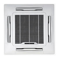
Daikin RXS35BVMB Service Manual (381 pages)
Sky-Air Indoor
Brand:
Daikin
| Category:
Air Conditioner
| Size: 7.24 MB
Table of Contents
Service Manual
1
Table of Contents
3
About this Manual
11
Combination Overview
12
System Outline
19
1 General Outline
21
What Is in this Chapter
21
Fcq35, 50, 60, 71B
22
Fcq100, 125B
24
Fcq71D
26
Fcq100, 125, 140D
28
Ffq25, 35, 50, 60B
30
Fbq35, 50B
32
Fbq60, 71B
34
Fbq100, 125B
36
Fdq125B
38
Fdq200, 250B
40
Fhq35, 50B
42
Fhq60, 71B
44
Fhq100B
46
Fhq125B
48
Fuq71B
50
Fuq100, 125B
52
Faq71B
54
Faq100B
56
Fdeq71, 100B
58
Fdeq125B
60
2 Specifications
63
What Is in this Chapter
63
Fcq - B
64
Fcq - D
65
Ffq - B
66
Fbq - B
67
Fdq - B
68
Fhq - B
69
Fuq - B
70
Faq - B
71
Technical Specifications
71
Electrical Specifications
71
Fdeq - B
72
What Is in this Chapter?
73
Indoor Piping
74
Pipe Connection Diameters
76
Piping Components
77
4 Wiring Diagrams
79
What Is in this Chapter
79
Fcq35, 50, 60B
80
Fcq71, 100, 125B
82
Fcq71, 100, 125, 140D
84
Ffq25, 35, 50, 60B
86
Fbq35, 50, 60B
88
Fbq71B
90
Fbq100, 125B
92
Fdq125, 200, 250B
94
Fhq35, 50, 60B
96
Fhq71, 100, 125B
98
Fuq71, 100, 125B
100
Faq71B
102
Faq100B
104
Fdeq71B
106
Fdeq100B
108
Fdeq125B
110
Switch Box Layout
113
What Is in this Chapter
113
Fcq35, 50, 60, 71B
114
Fcq100, 125B
115
Fcq71, 100, 125 140D
116
Ffq25, 35, 50, 60B
117
Fbq35, 50, 60, 71, 100, 125B
118
Fdq125, 200, 250B
119
Fhq35, 50, 60, 71, 100, 125B
120
Fuq71, 100, 125B
121
Faq71B
122
Faq100B
123
Fdeq71, 100, 125B
124
What Is in this Chapter
125
Fcq35, 50, 60B
126
Fcq71, 100, 125B
127
Fcq71, 100, 125, 140D
128
Ffq25, 35, 50, 60B
130
Fbq35, 50, 60, 71B & Fdeq71B
131
Fbq100, 125B & Fdeq100, 125B
132
Fdq125, 200, 250B
133
Fhq35, 50, 60B
134
Fhq71, 100, 125B
135
Fuq71, 100, 125B
136
Faq71B
137
Faq100B
138
What Is in this Chapter
141
Restart Standby
141
Automatic Restart
141
Forced Thermostat off
141
Freeze Prevention Function
141
Functions of Thermistors
142
Forced Operating Mode (Emergency Operation)
143
Outdoor Unit Identification Function
145
Simulated Operation Function
146
Restart Standby
147
Automatic Restart
148
Using Conditions for Remote Control Thermostat
149
Forced Thermostat off
151
Freeze Prevention Function
152
PMV Control
153
Thermostat Control
154
Drain Pump Control
155
Condensation Avoidance Control
157
Draft Avoidance Control 1
158
Draft Avoidance Control 2
159
Fan and Flap Operations
160
Indoor Unit Fan Control
161
Additional Checks for Troubleshooting
163
What Is in this Chapter
165
Checks
165
Overview of General Problems
165
Overview of General Problems
167
Equipment Does Not Operate
168
Equipment Operates but Does Not Provide Heating
174
Equipment Discharges White Mist
176
Equipment Produces Loud Noise or Shakes
177
Equipment Discharges Dust
178
Swing Flap Does Not Operate
180
Troubleshooting by LED Indications on the Indoor Unit
189
System Malfunctions
191
Overview of the Indoor Safety Devices
192
What Is in this Chapter?
193
Malfunctioning Indoor PCB
194
Malfunction of Drain Water Level System
195
Malfunctioning Drain System
197
Indoor Unit Fan Motor Lock
198
Malfunctioning Capacity Setting
200
Thermistor Abnormality
202
Malfunctioning Remote Controller Air Thermistor
204
Malfunctioning of Moisture Sensor System
205
What Is in this Chapter
209
Malfunction of Transmission between Indoor and Outdoor Unit (U4 or UF)
210
Remote Controller (U5)
213
Malfunction of Transmission between MAIN Remote Controller
213
And SUB Remote Controller
213
Malfunctioning Field Setting Switch
214
Centralized Address Setting Error
216
What Is in this Chapter?
217
Test Run Checks
218
What Is in this Chapter?
223
How to Change the Field Settings with the Wired Remote Control
224
How to Change the Field Settings with the Infrared Remote Control
226
Overview of the Field Settings on the Indoor Units
227
Overview of the Factory Settings on the Indoor Units
228
Setting the Ceiling Height
229
Setting the Filter Counter
230
Main/Sub Setting When Using Two Remote Controls
232
Setting the Centralized Group no
233
The Field Setting Levels
234
General Operation Data
238
Fbq100, 125B
243
Fbq60, 71B
243
Fdeq125B
243
Fcq35, 50, 60, 71B
244
Fcq100, 125B
246
Ffq25, 35, 50, 60B
248
Fbq35, 50B
250
Fbq60, 71B
252
Fbq100, 125B
254
Fdq125, 200, 250B
256
Fdeq71, 100B
258
Fdeq125B
260
Fcq71, 100, 125, 140D
262
Removal of Suction Grille
263
Removal of Air Filter
264
Removal of Decoration Panel
266
Removal of Horizontal Blade
268
Removal of Swing Motor
269
Removal of Switch Box
271
Removal of Pc Board
273
Removal of Humidity Sensor and Air Temperature Thermistor
275
Removal of Fan Motor
276
Removal of Drain Pan, Drain Pump, Float Switch
278
Removal of Heat Exchanger Temperature Thermistor
281
Ffq25, 50, 60B
282
Removal of Horizontal Vane
289
Removal of Fan Rotor and Fan Motor
295
Removal of Drain Pan
298
Removal of Drain Pump
299
Installation of Drain Pump
301
Replacement of Heat Exchanger Thermistor
304
Replacement of Heat Exchanger
306
Replacement of Pc Board
312
Replacement of Receiver Section of Infrared Remote Control
316
Fhq35, 50, 60, 71, 100, 125B
319
Removal of Air Filter and Suction Grille
320
Removal of Electrical Parts and Pc Boards
322
Removal of Fan Bearing
329
Removal of Bottom Panel and Drain Pan
331
Fuq71, 100, 125B
334
Removal of Fan
338
Removal of Air Flow Control Blade
349
Faq71B
351
Removal of Front Grille
354
Removal of Electrical Box
357
Removal of Heat Exchanger
358
Faq100B
362
Removal of Electrical Parts Box
365
Removal of Swing Louvre Unit
367
Removal of Fan Rotor
373
Advertisement
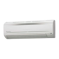
Daikin RXS35BVMB Service Manual (201 pages)
Brand:
Daikin
| Category:
Air Conditioner
| Size: 6.07 MB
Table of Contents
Table of Contents
3
Introduction
6
Safety Cautions
6
Caution in Repair
6
Cautions Regarding Products after Repair
7
Inspection after Repair
8
Using Icons
9
Using Icons List
9
Part 1 List of Function
10
Functions
11
Cooling Only
11
Heat Pump
14
Part 2 Specifications
18
Specifications
19
Cooling Only
19
Heat Pump
25
Part 3 Printed Circuit Board Connector Wiring Diagram
32
Printed Circuit Board Connector Wiring Diagram
33
Indoor Unit
33
Outdoor Unit
36
Part 4 Function and Control
38
Main Functions
39
Frequency Principle
39
Power-Airflow Dual Flaps, Wide Angle Louvers and Auto-Swing
41
Fan Speed Control for Indoor Units
42
Programme Dry Function
43
Automatic Operation
44
Night Set Mode
45
Intelligent Eye
46
Home Leave Operation
48
Inverter Powerful Operation
49
1.10 Other Functions
50
Function of Main Structural Parts
51
Main Structural Parts
51
Function of Thermistor
52
Cooling Only Model
53
Control Specification
54
Mode Hierarchy
54
Frequency Control
55
Controls at Mode Changing / Start-Up
57
Discharge Pipe Control
58
Input Current Control
58
Freeze-Up Protection Control
59
Heating Peak-Cut Control
59
Fan Control
60
Moisture Protection Function 1 (Securing of Differential Pressure and Blown Air Temperature)
60
Moisture Protection Function 2
61
Defrost Control
62
Electronic Expansion Valve Control
63
3.13 Malfunctions
66
Forced Operation Mode
67
3.15 Additional Function
67
Part 5 System Configuration
68
Sibe04
68
System Configuration
69
Instruction (in Case of FTK(X)S 25/35 BVMB)
70
Safety Precautions
70
Installation Site
71
Electrical Work
71
Names of Parts
72
I Outdoor Unit
73
Remote Controller
74
Preparation before Operation
75
AUTO·DRY·COOL·HEAT·FAN Operation
78
Adjusting the Air Flow Direction
80
POWERFUL Operation
82
OUTDOOR UNIT SILENT Operation
83
HOME LEAVE Operation
84
INTELLIGENT EYE Operation
86
TIMER Operation
88
Care and Cleaning
90
I Air Filter
91
Before a Long Idle Period
92
Trouble Shooting
93
Check Again
94
Disposal Requirements
95
Part 6 Service Diagnosis
96
Caution for Diagnosis
97
Problem Symptoms and Measures
98
Service Check Function
99
Troubleshooting
100
Error Codes and Description
100
Indoor Unit PCB Abnormality
101
Freeze-Up Protection Control or High Pressure Control
102
Fan Motor (AC Motor) or Related Abnormality
104
Thermistor or Related Abnormality (Indoor Unit)
105
Signal Transmission Error (between Indoor and Outdoor Units)
106
OL Activation (Compressor Overload)
107
Compressor Lock
108
Input over Current Detection
109
Four Way Valve Abnormality
110
Discharge Pipe Temperature Control
112
Position Sensor Abnormality
113
CT or Related Abnormality
114
Thermistor or Related Abnormality (Outdoor Unit)
116
Electrical Box Temperature Rise
118
Radiation Fin Temperature Rise
120
Output over Current Detection
122
Insufficient Gas
124
Over-Voltage Detection
126
High Pressure Control in Cooling
127
Check
129
How to Check
129
Four Way Valve Performance Check
130
Thermistor Resistance Check
131
Installation Condition Check
132
Discharge Pressure Check
133
Power Supply Waveforms Check
134
Capacitor Voltage Check
135
Power Transistor Check
135
Hall IC Check
136
Part 7 Removal Procedure
138
Indoor Unit
139
Removal of Air Filter
139
Removal of Front Grille
142
Removal of Front Grille
143
Removal of Horizontal Blade and Vertical Blade
145
Removal of Switch Box, PC Board and Swing Motor
147
Removal of Heat Exchanger
153
Install of Drain Plug
156
Removal of Fan Rotor and Fan Motor
157
Outdoor Unit
161
Removal of External Casing
161
Removal of Bell Mouth and Left Side Plate
164
Removal of PCB and Electrical Box
165
Removal of Propeller Fan and Fan Motor
171
Removal of Compressor Noise Absorption Pad
173
Removal of Partition Plate and Reactor
175
Removal of Four Way Valve and Motor Valve
178
Removal of Compressor
181
Part 8 Others
185
Others
185
Explanation
185
Jumper Settings
186
Part 9 Appendix
188
Piping Diagrams
189
Indoor Units
189
Outdoor Units
190
Wiring Diagrams
192
Indoor Units
192
Outdoor Units
193
Index
196
Drawings & Flow Charts
200
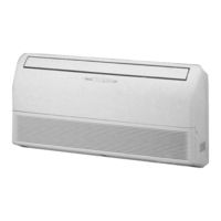
Daikin RXS35BVMB Service Manual (180 pages)
Inverter Pair Floor / Ceiling Suspended Dual Type B-Series
Brand:
Daikin
| Category:
Air Conditioner
| Size: 2.89 MB
Table of Contents
Table of Contents
3
Introduction
6
Safety Cautions
6
Caution in Repair
6
Cautions Regarding Products after Repair
7
Inspection after Repair
8
Using Icons
9
Using Icons List
9
Part 1 List of Functions
10
List of Functions
11
Cooling Only
11
Heat Pump
12
Part 2 Specifications
14
Specifications
15
Cooling Only
15
Heat Pump
17
Part 3 Printed Circuit Board
20
Connector Wiring Diagram
20
Printed Circuit Board Connector Wiring Diagram
21
Indoor Unit
21
Outdoor Unit
23
Part 4 Function and Control
26
Main Functions
27
Frequency Principle
27
Auto-Swing
29
Fan Speed Control for Indoor Units
30
Programme Dry Function
31
Automatic Operation
32
Night Set Mode
33
Home Leave Operation
34
Inverter Powerful Operation
35
Other Functions
36
Function of Main Structural Parts
37
Main Structural Parts
37
Function of Thermistor
38
Heat Pump Model
38
Cooling Only Model
39
Control Specification
40
Mode Hierarchy
40
Frequency Control
41
Controls at Mode Changing / Start-Up
43
Discharge Pipe Control
44
Input Current Control
44
Freeze-Up Protection Control
45
Heating Peak-Cut Control
45
Fan Control
46
Moisture Protection Function 1 (Securing of Differential Pressure and Blown Air Temperature)
46
Moisture Protection Function 2
47
Defrost Control
48
Electronic Expansion Valve Control
49
Target Discharge Pipe Temperature Control
51
Malfunctions
52
Forced Operation Mode
53
Additional Function
53
Part 5 System Configuration
54
System Configuration
55
Instruction
56
Safety Precautions
56
Installation Site
57
Electrical Work
57
Names of Parts
58
Remote Controller
60
Preparation before Operation
61
To Set the Clock
63
AUTO · DRY · COOL · HEAT · FAN Operation
64
To Change the Air Flow Rate Setting
65
Adjusting the Air Flow Direction
66
POWERFUL Operation
68
OUTDOOR UNIT SILENT Operation
69
HOME LEAVE Operation
70
TIMER Operation
72
To Use on Timer Operation
73
To Combine on Timer and off Timer
73
Care and Cleaning
74
Air Filter
75
Before a Long Idle Period
76
Troubleshooting
77
Check Again
78
Call the Service Shop Immediately
79
Disposal Requirements
79
Part 6 Service Diagnosis
80
Caution for Diagnosis
81
Problem Symptoms and Measures
82
Service Check Function
83
Troubleshooting
84
Error Codes and Description
84
Indoor Unit PCB Abnormality
85
Freeze-Up Protection Control or High Pressure Control
86
Fan Motor (AC Motor) or Related Abnormality
88
Thermistor or Related Abnormality (Indoor Unit)
89
Signal Transmission Error (between Indoor and Outdoor Units)
90
OL Activation (Compressor Overload)
91
Compressor Lock
92
Input over Current Detection
93
Four Way Valve Abnormality
94
Discharge Pipe Temperature Control
96
Position Sensor Abnormality
97
CT or Related Abnormality
98
Thermistor or Related Abnormality (Outdoor Unit)
100
Electrical Box Temperature Rise
102
Radiation Fin Temperature Rise
104
Output over Current Detection
106
Insufficient Gas
108
Over-Voltage Detection
110
High Pressure Control in Cooling
111
Check
113
How to Check
113
Four Way Valve Performance Check
114
Thermistor Resistance Check
115
Installation Condition Check
116
Discharge Pressure Check
117
Power Supply Waveforms Check
118
Inverter Units Refrigerant System Check
118
Capacitor Voltage Check
119
Power Transistor Check
119
Hall IC Check
120
Part 7 Removal Procedure
122
Indoor Unit
123
Removal of the Air Filter / Front Grille
123
Removal of the Front Panel
126
Removal of the Horizontal Blade
128
Removal of the Signal Receiver Unit / Swing Motor
129
Removal of the Discharge Grille
130
Removal of the Drain Pan
131
Removal of the Electrical Box / PCB
132
Removal of the Fan Rotor / Fan Motor
135
Removal of the Heat Exchanger
137
Outdoor Unit
139
Removal of External Casing
139
Removal of Bell Mouth and Left Side Plate
142
Removal of PCB and Electrical Box
143
Removal of Propeller Fan and Fan Motor
149
Removal of Compressor Noise Absorption Pad
151
Removal of Partition Plate and Reactor
153
Removal of Four Way Valve and Motor Valve
156
Removal of Compressor
159
Part 8 Others
162
Others
163
Test Run from the Remote Controller
163
Jumper Settings
164
Part 9 Appendix
166
Piping Diagrams
167
Indoor Units
167
Outdoor Units
168
Wiring Diagrams
170
Indoor Units
170
Outdoor Units
171
Index
174
Drawings & Flow Charts
178
Advertisement
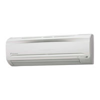
Daikin RXS35BVMB Pocket Manual (169 pages)
Service Diagnosis SPLIT & MULTI
Brand:
Daikin
| Category:
Air Conditioner
| Size: 3.94 MB
Table of Contents
Table of Contents
2
1 Diagnosis by LED
3
Indoor Unit
3
Outdoor Unit
5
2 Diagnosis by Remote Controller
7
To Know the Error Code
7
3 List of Applicable Models
12
Indoor Units
12
Outdoor Units
18
4 Error Codes and Description of Fault
22
Indoor Unit
22
Outdoor Unit
23
System
24
5 Troubleshooting
25
Indoor Unit
25
Outdoor Unit
36
System
125
Check
150
Advertisement
Related Products
Daikin RXS35E2V1B
Daikin RXS35DVMB
Daikin RXS35CVMB
Daikin RXS35CVMB9
Daikin RXS35C2VMB
Daikin RXS35J2V1B
Daikin RXS35F2V1B
Daikin RXS35L3V1B
Daikin RXS35L2V1B
Daikin RXS35LVMA
Daikin Categories
Air Conditioner
Heat Pump
Remote Control
Chiller
Fan
More Daikin Manuals
Login
Sign In
OR
Sign in with Facebook
Sign in with Google
Upload manual
Upload from disk
Upload from URL