Sign In
Upload
Manuals
Brands
Congatec Manuals
Motherboard
COM Express conga-MEVAL
Congatec COM Express conga-MEVAL Manuals
Manuals and User Guides for Congatec COM Express conga-MEVAL. We have
1
Congatec COM Express conga-MEVAL manual available for free PDF download: Manual
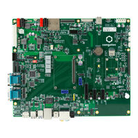
Congatec COM Express conga-MEVAL Manual (58 pages)
Brand:
Congatec
| Category:
Motherboard
| Size: 4 MB
Table of Contents
Table of Contents
8
Introduction
11
COM Express™ Concept
11
Conga-MEVAL
11
Order Number
12
Table 1 Order Description
12
Block Diagram
13
Connector Layout
14
Specifications
15
Feature List
15
Table 2 Feature Summary
15
Mechanical Dimensions
16
Environmental Specifications
16
Connectors and Features
17
COM Express a - B Connector
17
Table 3 Module Type 10 Connector Pinout-Rows a and B
17
Power Supply Connectors
19
Standard ATX Connector
19
Table 4 X58 - ATX PSU Control Description
19
Table 5 X60 - ATX 5V Standby Connection
19
Table 6 X59 - ATX Pinout
20
Table 7 X128 - ATX (4-Pin)
20
DC Banana Jack
21
Optional DC Banana Jack
21
Table 8 M22/M23 - DC Banana Jack
21
Table 9 M29/M30 - Optional DC Banana Jack
21
Table 10 X76 - Voltage Regulator Control
21
Status Leds
22
Table 11 Power Leds Status
22
PWR_OK Signal
23
Power-Up Control
23
Module Type Detection
23
Table 12 X57 - Module PWR_OK Signal
23
Table 13 Module Type Detection Pinout Description
23
CMOS Battery
24
Pcie Connectors
25
Pcie X4 Slot
26
Pcie X1 Slot
26
Table 14 X75 - Pcie X4 Slot Configuration
26
Table 15 Pcie X1 Lane Routing
26
Mini Pcie Socket
27
Table 16 X107 - USB Port 5 Routing
27
Table 17 D4-D6 - Mini Pcie Leds Description
27
SD Card Slot
28
Display Interfaces
28
Table 18 X22 - SDIO/GPIO Connection
28
Edp
29
Table 19 X82 - Edp Pinout Description
29
Panel Power and Backlight Jumpers
30
Table 20 X87 - Edp/Lvds Selection
30
Table 21 X122 - Edp Panel Power
30
Table 22 X34 - Backlight Voltage Selection
30
Lvds
31
Table 23 X87 - Edp/Lvds Selection
31
Table 24 X65 - LVDS Connector (Top Side)
31
Table 25 CN6 - LVDS Connector (Bottom Side)
32
Panel Power and Backlight Jumpers
33
Panel and Backlight Power Supply
33
Table 26 X33 - LVDS Panel Power
33
Table 27 X34 - Backlight Voltage Selection
33
Table 28 X35 - LVDS Power Pinout Description
33
Backlight Enable Polarity
34
Flat Panel Configuration Data
34
Table 29 X36 - Backlight Enable Polarity
34
Flat Panel and Backlight Power Supply Connection
35
Universal Serial Bus (USB)
36
Dual Stacked USB 3.1 Gen 2 Type-A
37
Dual Stacked USB 2.0 Type-A
37
USB Type-B
38
Sata
38
Table 30 X107 - USB5 Route Configuration
38
Table 31 X21 - External LED Header
38
Disk Drive Power Connector
39
Gigabit Ethernet
39
Table 32 X5 Status Leds
39
Table 33 D1 - Onboard Gbe Link LED
39
Audio Interfaces
40
Table 34 X6 - Ethernet Leds Power Configuration
40
Audio Jacks
41
Table 35 CN2 Pinout Description
41
Optical S/PDIF-Out
42
HDA Adapter/Debug Header
42
Table 36 X38 Pinout Description
42
Digital MIC
43
I 2 C Bus
43
Table 37 X123 Pinout
43
SM Bus
44
I 2 C Digital I/O
44
Table 38 X50/X51 Pinout Description
44
SPI Flash Header
45
Table 39 X20 - SPI Flash Header
45
Table 40 SW M13 - BIOS Boot Device Selection
45
LPC Interfaces
46
LPC Header
46
Table 41 CN7 - LPC Header
46
Table 42 X104 - Onboard TPM Activation
46
Super I/O Configuration
47
Table 43 X105 - Super I/O Activation
47
Table 44 X78 - SIO Upper Byte
47
Table 45 X79 - SIO Lower Byte
47
Serial Ports
48
COM Ports 0-3
48
Table 46 X10,X11 - COM Port 0-3 Pinout Description
48
Module Serial Port 0-1/CAN Bus
49
Table 47 X115, X116 - Module Serial Port 0-1
49
Table 48 X111 - SER1/CAN Bus Selection
49
Table 49 X109 - CAN Bus
49
Table 50 X110 - CAN Bus Mode
49
CPU Fan Header
50
Table 51 X56 - CPU Fan Header
50
Table 52 X55 - CPU Fan Voltage Selection
50
Smart Battery Header
51
Programming Header - Internal Use Only
51
Table 53 X52 - SBM Header Pinout
51
Table 54 X80/X81 - Bus Selection
51
Module Detection - Internal Use Only
52
Feature Connector
52
Table 55 X53 - Feature Connector
52
Additional Features
54
Buttons
54
Power
54
Reset
54
Lid
54
Sleep
55
Fast Standby Discharge
55
Beeper
55
Table 56 X83 - Beeper Configuration
55
Debug Display
56
Ground Test Points
56
Table 57 X63 - POST Code Decoder
56
External Power LED
57
Wireless Disable
57
Table 58 X54 - External Power LED
57
Table 59 X103 - Mini Pcie Wireless Disable Signal
57
Mechanical Dimensions
58
Advertisement
Advertisement
Related Products
Congatec COM Express conga-TCA
Congatec conga-IGX
Congatec COM Express conga-BM67
Congatec COM Express conga-BS67
Congatec COM Express conga-TR3
Congatec conga-IC175
Congatec Qseven conga-QA5
Congatec conga-PA5 Series
Congatec conga-IA4
Congatec SMARC conga-SMC1
Congatec Categories
Motherboard
Computer Hardware
Control Unit
Single board computers
Microcontrollers
More Congatec Manuals
Login
Sign In
OR
Sign in with Facebook
Sign in with Google
Upload manual
Upload from disk
Upload from URL