Sign In
Upload
Manuals
Brands
Chore-Time Manuals
Farm Equipment
C2 PLUS
Chore-Time C2 PLUS Manuals
Manuals and User Guides for Chore-Time C2 PLUS. We have
3
Chore-Time C2 PLUS manuals available for free PDF download: Installation And Operator's Manual
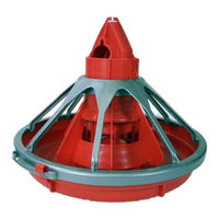
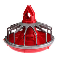
Chore-Time C2 PLUS Installation And Operator's Manual (68 pages)
Pan Breeder Feeder and Male Feeder
Brand:
Chore-Time
| Category:
Farm Equipment
| Size: 7 MB
Table of Contents
Chore-Time Warranty
2
Table of Contents
4
About this Manual
6
Safety Information
6
Safety Instructions
7
Follow Safety Instructions
7
Decal Descriptions
7
DANGER: Moving Auger
7
DANGER: Electrical Hazard
7
Caution
7
General
7
Information
7
Manufacturer's Recommendations: Birds Per Pan
8
Planning the Floor Feeding System
9
General Installation Information
10
Laying out the Suspension System
10
Installing the Suspension System
11
Power Lift Winch Installation
11
Installing the Main Winch Cable
12
Screw Hook Installation
13
Ceiling Hook Installation
14
Steel Truss Installations
14
Steel Truss Welded Installations
14
Wood Truss Installations
14
Drop Installation
15
Power Winch Installation
16
Drop Installation
18
Winch Control
19
Installation
19
Operation
19
Hopper Assembly Procedure
20
Feeder Assembly Procedure
22
Assembly Box Construction
22
Pan Assembly Procedure
23
Feeder Line Assembly & Suspension
24
Feeder Pan and Tube Assembly Process
24
Assemble and Suspend the Feeder Line
24
Indexing Chart for Pan Breeder Feeders
27
For Systems Using 9' (2.7 M) Auger Tube and 696 RPM Power Units
27
For Systems Using 12' (3.6 M) Auger Tube and 696 RPM Power Units
28
Indexing the Male Feeder
29
Indexing Chart for Male Feeders
30
For Systems Using 9' (2.7 M) Auger Tube and 348 RPM Power Units
30
For Systems Using 12' (3.6M) Auger Tube and 696 RPM Power Units
31
Model C2 Plus Feeder Lock Installation
32
Installing the End Control, Boot Assembly, and Auger
33
Auger Installation
34
Auger Brazing
38
Anti-Roost Installation
39
Feeder Management
42
Maintenance
43
Floor Feeding System Maintenance
43
Gear Head Maintenance
43
Mechanical Switch Adjustment Procedure for Control Units
44
SENSOR PLUS Sensor Switch Adjustment for Control Units
44
Feeder Line
44
Power Lift Winch Maintenance
45
Trouble Shooting the Floor Feeding System
46
Wiring Diagrams
47
Winch Control Wiring Diagram with 29820-3 Tower Limit Switch
47
Winch Control Wiring Diagram with 39464 Limit Switch
47
Male Feeder System Wiring Diagrams: Single Phase(Ø)
48
Single Phase(Ø) Wiring Diagram
48
Single Phase(Ø) Wiring Diagram: W/Motor Starter
48
Male Feeder System Wiring Diagrams: Three Phase(Ø)
49
Three Phase(Ø) Wiring Diagram: 220/230 V
49
Three Phase(Ø) Wiring Diagram: 380/415 V
49
Electric Power Lift Wiring Diagram
50
Parts Listing
51
Standard Breeder Pans
51
Standard Breeder Pans with Shut-Off
52
Shallow G™ Plus Breeder Pans with Slide Shut-Off
53
Shallow G™ Plus Breeder Pans
54
Shallow Breeder Pans
55
34812 Winch Control Parts Listing
56
14613 Switch Box Assembly
56
8798 Switch Assembly
57
Mechanical End Control
58
Sensor Plus™ End Control
60
Boot Assemblies
62
Single: Part No. 6822
62
Twin: Part No. 6824
62
Miscellaneous Suspension Components
63
14580 Electric Winch Kit
64
Feeder Line Components
65
47687 Power Winch
66
Indexing Gauge
66
Power Unit Assemblies
67
Advertisement
Chore-Time C2 PLUS Installation And Operator's Manual (64 pages)
Proximity Sensor Feeding System
Brand:
Chore-Time
| Category:
Farm Equipment
| Size: 7 MB
Table of Contents
Chore-Time Warranty
2
Table of Contents
3
Manufacturer's Recommendations: Birds Per Pan
5
About this Manual
6
Safety Information
6
Safety Instructions
7
Follow Safety Instructions
7
Decal Descriptions
7
DANGER: Moving Auger
7
DANGER: Electrical Hazard
7
Caution
7
General
7
Support Information
7
Planning the Suspension System
8
General Installation Information
9
Laying out the Suspension System
9
Installing the Suspension System
10
Power Lift Winch Installation
10
Installing the Main Winch Cable
11
Screw Hook Installation
12
Ceiling Hook Installation
13
Drop Installation
13
Hopper Assembly Procedure
14
Assembly
14
Suspend the Hopper
14
Feeder Pan Assembly
15
Feeder Line Assembly and Suspension
15
Feeder Pan and Tube Assembly Process
15
Assemble and Suspend the Feeder Line
15
Installing the End Control, Boot Assembly, and Auger
18
Auger Installation
18
Auger Installation
22
Auger Brazing
25
MID-Line Control
26
Anti-Roost Assembly
28
Wiring
31
End Control with Electronic Sensor Internal Wiring
31
Electronic Sensor Control Wiring Diagram
31
MID Control with Electronic Sensor Internal Wiring
31
Mechanical Switch Single Phase(Ø) Wiring Diagram
32
Mechanical Switch Single Phase(Ø) Wiring Diagram with Motor Starter
32
Mechanical Switch Three Phase(Ø) Wiring Diagram: 220 V
33
Mechanical Switch Three Phase(Ø) Wiring Diagram: 380/415 V
33
Electronic Sensor Three Phase (Ø) Wiring
34
Troubleshooting
35
Maintenance
36
Floor Feeding System Maintenance
36
Gear Head Maintenance
36
Mechanical Switch Adjustment Procedure for Control Units
37
Feeder Line
38
Power Lift Winch Maintenance
38
Management
39
Initial Start-Up of the Feeding System
39
General Operation of the MODEL C2® PLUS and MODEL G™ PLUS Feeders
40
End Control and MID Line Control Pans
41
Controlling the Feeders (Optional Equipment)
41
Electro-Guard Operation
41
Parts List
42
150# Plastic Hopper
42
200# Hopper Components
43
100 # Hopper Components
44
Hopper Mount Bracket (Optional)
45
Single Boot Components Part No. 6822
45
Twin Boot Components Part No. 6824
46
Feeder Line Components
47
C2 PLUS Standard with Two Piece Top
48
C2 PLUS Standard with One Piece Top
48
MODEL C2 PLUS Shallow with Two Piece Top
49
C2 PLUS Shallow with One Piece Top
49
MODEL C2 PLUS and G PLUS with Extended Fins
50
MODEL G PLUS Standard with Two Piece Top
51
MODEL G PLUS Standard with One Piece Top
51
MODEL G PLUS Shallow with Two Piece Top
52
Power Unit Assemblies
53
Power Unit Assembly Part Numbers
53
Mechanical End Control
54
Mechanical MID Line Control
56
Electronic Sensor End Control (56706)
58
Electronic Sensor MID Line Control (56934)
60
MODEL G PLUS Pan Extension (Optional)
61
2883 Power Winch
61
Miscellaneous Suspension Components
62
Chore-Time C2 PLUS Installation And Operator's Manual (62 pages)
Brand:
Chore-Time
| Category:
Toddler feeding
| Size: 7 MB
Table of Contents
Chore-Time Warranty
2
Table of Contents
4
About this Manual
6
Safety Information
6
Safety Instructions
7
Follow Safety Instructions
7
Decal Descriptions
7
DANGER: Moving Auger
7
DANGER: Electrical Hazard
7
Caution
7
General
7
Information
7
Manufacturer's Recommendations: Birds Per Pan
8
Planning the Floor Feeding System
9
General Installation Information
10
Laying out the Suspension System
10
Installing the Suspension System
11
Power Lift Winch Installation
11
Installing the Main Winch Cable
12
Screw Hook Installation
13
Ceiling Hook Installation
14
Drop Installation
15
Feeder Pan Assembly
16
Feeder Line Assembly and Suspension
16
Feeder Pan and Tube Assembly Process
16
Assemble and Suspend the Feeder Line
17
Installing the End Control, Boot Assembly, and Auger
19
Auger Installation
19
Auger Brazing
24
Anti-Roost Installation
25
MID-Line Control
28
Feeder Management and Operation
31
Initial Start-Up of the Feeding System
31
General Operation of the MODEL C2® PLUS and MODEL G™ PLUS Feeders
32
End Control and MID Line Control Pans
33
Controlling the Feeders (Optional Equipment)
33
Electro-Guard Operation
34
Optional Slide Shut-Off
34
Optional MODEL G Plus Pan Extension
34
Maintenance
35
Floor Feeding System Maintenance
35
Gear Head Maintenance
35
Mechanical Switch Adjustment Procedure for Control Units
36
SENSOR PLUS™ Sensor Switch Adjustment for Control Units
36
Feeder Line
36
Power Lift Winch Maintenance
37
Trouble Shooting the Floor Feeding System
38
Wiring Diagrams
39
SENSOR PLUS Internal Wiring
39
SENSOR PLUS Control Wiring Diagram
39
Mechanical Switch Single Phase(Ø) Wiring Diagram
40
Mechanical Switch Single Phase(Ø) Wiring Diagram with Motor Starter
40
Mechanical Switch Three Phase(Ø) Wiring Diagram: 220 V
41
Mechanical Switch Three Phase(Ø) Wiring Diagram: 380/415 V
41
Parts Listing
42
200# Hopper Components
42
100 # Hopper Components
43
Hopper Mount Bracket (Optional)
44
Single Boot Components Part No. 6822
45
Twin Boot Components Part No. 6824
45
Feeder Line Components
46
Model C2 Plus Feeder Pan Assemblies
47
Model C2 Plus Shallow Feeder Pan Assemblies
48
Model G Plus Feeder Pan Assemblies
49
Model G Plus Shallow Feeder Pan Assemblies
50
Power Unit Assemblies
51
Power Unit Assembly Part Numbers
51
Mechanical End Control
52
Mechanical MID Line Control
54
SENSOR PLUS End Control
56
SENSOR PLUS MID Line Control
58
Model G Plus Pan Extension (Optional)
59
2883 Power Winch
59
Miscellaneous Suspension Components
60
Advertisement
Advertisement
Related Products
Chore-Time Chore-Tronics 2
Chore-Time Control
Chore-Time C
Chore-Time C2
Chore-Time Chore-Tronics
Chore-Time Chore-Tronics 3 Auto Adjust PDS 16 Station
Chore-Time Chore-Tronics Natural Ventilation
Chore-Time Chore-Tronics Broadcaster
Chore-Time 40170
Chore-Time 55
Chore-Time Categories
Fan
Farm Equipment
Control Unit
Industrial Equipment
Controller
More Chore-Time Manuals
Login
Sign In
OR
Sign in with Facebook
Sign in with Google
Upload manual
Upload from disk
Upload from URL