Chore-Time C2 Plus Installation And Operator's Manual
Hide thumbs
Also See for C2 Plus:
- Installation and operator's manual (64 pages) ,
- Installation and operator's manual (68 pages)

Related Manuals for Chore-Time C2 Plus


Summary of Contents for Chore-Time C2 Plus
- Page 1 MODEL C2® Plus & MODEL G™ Plus Feeding System Installation and Operators Manual 1255-111 10/2000 August 2004 MF1255C...
-
Page 2: Chore-Time Warranty
CHORE-TIME® product manufactured by it to be free from defects in material or workmanship for one-year from and after the date of initial installation by or for the original purchaser. If such a defect is found by Chore-Time to exist within the one-year period, Chore-Time will, at its option, (a) repair or replace such product free of charge, F.O.B. - Page 3 Warranty. Chore-Time shall not be liable for any consequential or special damage which any purchaser may suffer or claim to suffer as a result of any defect in the product. “Consequential” or special damages” as used herein include, but are not limited to, lost or damaged products or goods, costs of transportation, lost sales, lost orders, lost income, increased overhead, labor and incidental costs and operational inefficiencies.
-
Page 4: Table Of Contents
Chore-Time Warranty ........ - Page 5 Model C2 Plus Shallow Feeder Pan Assemblies ........
-
Page 6: About This Manual
About This Manual MODEL C2® Plus & MODEL G™ Plus Feeding System About This Manual The intent of this manual is to help you in two ways. One is to follow step-by-step in the order of assembly of your product. The other way is for easy reference if you have questions in a particular area. Important: Read ALL instructions carefully before starting construction. -
Page 7: Safety Instructions
General Information The Chore-Time MODEL C2® Plus and MODEL G™ Plus Feeding Systems are designed to feed poultry feed types. Using this equipment for any other purpose or in a way not within the operating recommendations specified in this manual will void the warranty and may cause personal injury. -
Page 8: Manufacturer's Recommendations: Birds Per Pan
* NOTICE: The above Manufacturer’s recommendations do not constitute a product warranty and are in no way to be considered as a guarantee of performance for poultry production. In addition, the above information in no way alters or revises the terms and conditions of any applicable Chore-Time manufacturer’s warranty. MF1255C... -
Page 9: Planning The Floor Feeding System
MODEL C2® Plus & MODEL G™ Plus Feeding System Planning the Floor Feeding System Planning the Floor Feeding System 1. Select the House Layout. A. Optional Mid Line Controls may be used for partial house brooding. See Figure 1. 10' [3 m] 10' [3 m] Minimum Minimum... -
Page 10: General Installation Information
17 lbs [7.7 kg] per minute. This rating is based on feed with a density of 40 lbs per cubic foot [640 kg per cubic meter]. Single phase 60 Hz and single and three phase 50 Hz Power Units are available for the Model C2 Plus , G Plus Feeders. -
Page 11: Installing The Suspension System
MODEL C2® Plus & MODEL G™ Plus Feeding System Installing the Suspension System B. For systems over 350' [107 m] 3) Large Pulley with Double Clamps 1) Full Line Suspension Kit 4) Power Lift Winch Support 6) Small Pulley 2) Hopper Support 5) Roof Trusses and Screw Hook 12) Hopper... -
Page 12: Installing The Main Winch Cable
Adequate overhead structure must be provided to support the weight of the feeders, hoppers, power units, etc. The Suspension System is the same for the Model C2 Plus and G Plus Feeders. The type of installation required depends on the feeder line length. -
Page 13: Screw Hook Installation
Screw Hook Installation The recommended distance between the 1) 3/16" [5 mm] drops for the Model C2 Plus & G Plus is 8’ 2) 3/32" [2 mm] Main Winch Cable [2.4 m] on center. Do not exceed 10’ [3 m] Drop Cable spacing on drop lines. -
Page 14: Ceiling Hook Installation
Installing the Suspension System MODEL C2® Plus & MODEL G™ Plus Feeding System Ceiling Hook Installation The ceiling hook may be used in a variety of installations. Depending on your ceiling or rafter type, install the Ceiling Hooks as shown in Figures 14 - 17. Steel Truss Installations 2) Cable Travel 1) Secure Ceiling Hook to truss... -
Page 15: Drop Installation
MODEL C2® Plus & MODEL G™ Plus Feeding System Installing the Suspension System 6. After securing the Ceiling Hook to the truss, slide the hook of a Swivel Pulley into the slot, as shown 1) Wood Truss in Figure 17. 2) Ceiling Bracket 3) 1/4"... -
Page 16: Feeder Pan Assembly
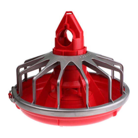
Feeder Pan over on the top of the Grill and Cones. Seat the Feeder Pan in the ring of the Grill. With the Feeder Pan fully seated rotate the pan clockwise to lock in place. Assemble the remaining Feeders. Rotate the Feeder Pan to lock into the Grill C2 Plus Grill Adjustment Cone Support Cone Feeder Pan 1255-114 4/2001 Figure 19. -
Page 17: Assemble And Suspend The Feeder Line
1255-123 3/2001 Figure 21. Attaching Feeder Tube Assemblies 3. To achieve total feed drop out all along the system, the Chore-Time Logo should be centered at the crown of the tubes and all the Hangers should be installed as shown in Figure 22. - Page 18 Chore-Time Logo is on crown of tube. make sure the clamps are located, as shown in Figure 24.
-
Page 19: Installing The End Control, Boot Assembly, And Auger
See Figure 27. DO NOT INSTALL THE POWER UNIT AT THIS TIME. End Control Unit Feed Line Control Tube CHOR E-TIME EQUIPMEN T A DIVISION OF CTB INC. MIL FORD, INDIANA 46542-2000 42680 MODEL C2 PLUS END CONTROL WITH PROXIMITY SWITCH 2529-710 DANGER ELECTROCUTION HAZARD! Do not open this control box until electrical power is disconnected at circuit breakers. - Page 20 Feeder Line Assembly and Suspension MODEL C2® Plus & MODEL G™ Plus Feeding System Cut the leading 18" [450 mm] and last 18" [450 mm] off each roll of auger. Also, cut out any other distorted auger sections and reconnect the auger as specified in the Auger Brazing section of this manual.. CAUTION KEEP HANDS AWAY FROM PINCH POINTS WHEN INSTALLING...
- Page 21 MODEL C2® Plus & MODEL G™ Plus Feeding System Feeder Line Assembly and Suspension 4. Slide the Drive Tube and flat washer over the output shaft on the Power Unit, as shown in Figure 30. 5. Continue installing auger until the auger reaches the Control Unit end of the feeder line. 6.
- Page 22 3) to length. Slide the wires from the end control through the Flex Conduit (item 3). Install the Flex Conduit (item 3) in the connectors. Connect the wires to the Feed Line Motor (item 2). CHORE-TIME EQUIPMENT A DIVISION OF CTB INC. MILFORD, INDIANA 46542-2000 42680 MODEL C2 PLUS END CONTROL WITH PROXIMITY SWITCH 2529-710 DANGER...
- Page 23 MODEL C2® Plus & MODEL G™ Plus Feeding System Feeder Line Assembly and Suspension Use a hacksaw or bolt cutters to cut the auger at the stretched auger mark. 1) Locking Pliers 2) Use a hacksaw or bolt cutters to cut the auger 4) Boot under Feed Hopper 3) Pull an extra 8"...
-
Page 24: Auger Brazing
Feeder Line Assembly and Suspension MODEL C2® Plus & MODEL G™ Plus Feeding System Auger Brazing The auger should be brazed if it is necessary to splice or lengthen it. A bronze, flux coated rod is recommended. The ends of the auger should butt against each other, DO NOT THREAD INSIDE EACH OTHER. See Figure 36. -
Page 25: Anti-Roost Installation
MODEL C2® Plus & MODEL G™ Plus Feeding System Feeder Line Assembly and Suspension Anti-Roost Installation 1. Unroll the bulk anti-roost cable. Note: If the cable is unrolled as shown in Figure 37, taking 5 loops of the coil with one hand, then changing hands to remove 5 loops as it is unrolled, it will lie flat during installation. - Page 26 Feeder Line Assembly and Suspension MODEL C2® Plus & MODEL G™ Plus Feeding System 9. At the control unit, after clamping the cable to the spring, cut the cable about 8" to 10" [200 to 250 mm] longer than necessary. Feed the end of the cable through the center of the spring, around the first insulator on the control unit, and clamp the cable using the cable clamp supplied with the control unit.
- Page 27 MODEL C2® Plus & MODEL G™ Plus Feeding System Feeder Line Assembly and Suspension 3) Anti-Roost Wire 2) Insulated Charger Wire 1) Line Charger 1255-92 9/2000 Figure 42. Line Charger Installation 12. The anti-roost system must be on a separate electrical circuit, allowing the system to be disconnected by a switch near the door.
-
Page 28: Mid-Line Control
Mid-Line Control MODEL C2® Plus & MODEL G™ Plus Feeding System Mid-Line Control Mid-Line Control Units are available for the Model C2 Plus & G Plus Feeders. The Mid-Line Controls are shown in Figure 43. CHORE-TIME EQUIPMENT CHORE-TIME EQUIPMENT A DIVISION OF CTB INC. - Page 29 The Mid-Line Control makes it possible to operate the feeding system when birds are confined away from the End Control Unit. Chore-Time recommends placing the Mid-Line Control Feeder at least 2 pans away from the curtain or partition. See Figure 44.
- Page 30 Assemble the Mid-Line Control to the Feeder Tube as shown in Figure 47. CHORE-TIME EQUIPMENT A DIVISION OF CTB INC. MILFORD, INDIANA 46542-2000 42663 MODEL C2 PLUS INTERMEDIATE CONTROL WITH PROXIMITY SWITCH 2529-711 DANGER b. Attach the Switch Box Assembly to the Feeder...
-
Page 31: Feeder Management And Operation
MODEL C2® Plus & MODEL G™ Plus Feeding System Feeder Management and Operation Feeder Management and Operation This section provides you with valuable information concerning feeder operation and management. It is important that you read this information and understand how the feeding system was designed to operate. Once you become familiar with the system, you may custom operate it to fit your individual needs. -
Page 32: General Operation Of The Model C2® Plus And Model G™ Plus Feeders
The Model C2 Plus and G Plus feeders have a feed flood windows which allows the feeder pan, when lowered to the floor, to be filled with feed for the brooding of young birds. Start young birds with the feeder line lowered so the feed pans are resting on the floor and the feed flood windows are completely open. -
Page 33: End Control And Mid Line Control Pans
The MODEL C2 Plus and G Plus Feeding Systems may be controlled by the #34385 Control Panel or the #34574 Time Clock Control. Refer to the instructions supplied with each control for information. -
Page 34: Electro-Guard Operation
Optional Slide Shut-Off MODEL C2® Plus & MODEL G™ Plus Feeding System Electro-guard Operation The electro-guard chargers should be operated on a separate electrical circuit so the anti-roost system can be shut off using a switch next to the entrance door when someone enters the building. Birds are less likely to become wild and flighty if the anti-roost is off when people are in the building. -
Page 35: Maintenance
Maintenance Maintenance Floor Feeding System Maintenance The Model C2 Plus and Model G Plus Feeders require minimum maintenance. However, a routine periodic inspection of the equipment will prevent unnecessary problems. Maintenance should be done by a qualified technician. ALWAYS DISCONNECT POWER TO THE SYSTEM WHEN SERVICING OR MAINTAINING THE EQUIPMENT. -
Page 36: Mechanical Switch Adjustment Procedure For Control Units
Maintenance MODEL C2® Plus & MODEL G™ Plus Feeding System Mechanical Switch Adjustment procedure for Control Units Refer to Figure 55. 1)Adjustment Nut A. Turn the adjustment nut counter- clockwise until the switch clicks. B. Turn the adjustment nut clockwise until the switch clicks. -
Page 37: Power Lift Winch Maintenance
MODEL C2® Plus & MODEL G™ Plus Feeding System Maintenance If the system must be disassembled, extreme caution must be used to prevent injury from springing auger. Refer to Figure 57. 1. Disconnect power to the entire system. 2. Loosen the Tube Clamp on the bearing at the hopper end of the system. -
Page 38: Trouble Shooting The Floor Feeding System
Trouble Shooting the Floor Feeding System MODEL C2® Plus & MODEL G™ Plus Feeding System Trouble Shooting the Floor Feeding System ALWAYS DISCONNECT POWER TO THE SYSTEM WHEN SERVICING OR MAINTAINING THE EQUIPMENT. FAILURE TO DISCONNECT POWER MAY CAUSE INJURY OR DEATH. Service and maintenance work should be done by a qualified technician only. -
Page 39: Wiring Diagrams
A DI VISION OF C TB IN C . M ILFO R D, IN DIA NA 46542-2000 42663 MOD EL C 2 PL US 42680 MODE L C2 PLUS IN TERME DIATE CONTR O L EN D CON TROL W ITH PR OXIMITY S WITCH... -
Page 40: Mechanical Switch Single Phase(Ø) Wiring Diagram
Wiring Diagrams MODEL C2® Plus & MODEL G™ Plus Feeding System Mechanical Switch Single Phase(Ø) Wiring Diagram FROM DISCONNECT OR FEEDER LINE MOTOR CONTROL DISCONNECT 220/230 VOLTS 50/60 HZ SINGLE PHASE WIRING DIAGRAM 220/230 VOLTS 50/60 HZ SINGLE PHASE MID LINE END CONTROL UNIT CONTROL UNIT... -
Page 41: Mechanical Switch Three Phase(Ø) Wiring Diagram: 220 V
MODEL C2® Plus & MODEL G™ Plus Feeding System Wiring Diagrams Mechanical Switch Three Phase(Ø) Wiring Diagram: 220 V. FROM DISCONNECT OR CONTROL DISCONNECT 220 VOLTS 50 HZ TO ADDITIONAL THREE PHASE FEEDER LINES PHASE PHASE PHASE SET OF FUSES SHORT CIRCUIT PROTECTION MID LINE... -
Page 42: Parts Listing
Parts Listing MODEL C2® Plus & MODEL G™ Plus Feeding System Parts Listing 200# Hopper Components 1660-02 10/2000 Item Description Part No. Hopper Cover (optional) 28206 Tube Support Assembly 14367 Hopper Side 2680 Boot Hanger 2671 Hanger Bracket Assembly 2681 Adjustment Bracket 2706 Hair Pin... -
Page 43: 100 # Hopper Components
MODEL C2® Plus & MODEL G™ Plus Feeding System Parts Listing 100 # Hopper Components 1660-01 10/2000 Description Part No. Hopper Cover (w/o hole) 28211 Hopper Cover (w/ hole) 28212 Hopper Hanger 28165 Adjustment Bracket 2706 Clevis Pin, 5/16'' x 1'' 2797-1 Hair Pin 2664... -
Page 44: Hopper Mount Bracket (Optional)
Parts Listing MODEL C2® Plus & MODEL G™ Plus Feeding System Hopper Mount Bracket (Optional) Part Number 49358 - Hopper Suspension Kit Item Description Part No. Part No. Single Boot Twin Boot Clevis Pin, 5/16'' x 1'' 2797-1 2797-1 Adjustment Bracket 2706 2706 Hair Pin... -
Page 45: Single Boot Components Part No. 6822
MODEL C2® Plus & MODEL G™ Plus Feeding System Parts Listing Twin Boot Components Part No. 6824 Item Description Part No. Item Description Part No. Boot Weldment 3932 Setscrew 47867 Tube Clamp 24063 Anchor and Bearing Ass’y 39372 29373 Cannonball 3531 Outlet Tube 4556... -
Page 46: Feeder Line Components
Parts Listing MODEL C2® Plus & MODEL G™ Plus Feeding System Feeder Line Components 1660-06 10/2000 Item Description Part No. 1/16'' Cable 1922 Charger Wire (165') 28994-165 Charger Wire (330') 28994-330 Spring 7551 1/16'' Cable Clamp 1826 Auger 6820-0 Tube Clamp 24063 Anti-Roost Bracket 24060... -
Page 47: Model C2 Plus Feeder Pan Assemblies
MODEL C2® Plus & MODEL G™ Plus Feeding System Parts Listing MF1255C... -
Page 48: Model C2 Plus Shallow Feeder Pan Assemblies
Parts Listing MODEL C2® Plus & MODEL G™ Plus Feeding System MF1255C... -
Page 49: Model G Plus Feeder Pan Assemblies
MODEL C2® Plus & MODEL G™ Plus Feeding System Parts Listing MF1255C... -
Page 50: Model G Plus Shallow Feeder Pan Assemblies
Parts Listing MODEL C2® Plus & MODEL G™ Plus Feeding System MF1255C... -
Page 51: Power Unit Assemblies
MODEL C2® Plus & MODEL G™ Plus Feeding System Parts Listing Power Unit Assemblies Item Description 3259-8 3259-25 3259-84 3259-85 3259-98 3259-100 3259-128 Part No. Part No. Part No. Part No. Part No. Part No. Part No. Pinion Assembly 5046 5046 5046 5046... -
Page 52: Mechanical End Control
MODEL C2® Plus & MODEL G™ Plus Feeding System Mechanical End Control CHORE-TIME EQUIPMENT A DIVISION OF CTB INC. MILFORD, INDIANA 46542-2000 40943 MODEL C2 PLUS END CONTROL WITH WINDOW CONTACT RATINGS: 1/2 H.P. @ 115 VAC 1 H.P. @ 230 VAC... - Page 53 Anti-Roost Guard 2798 2798 2798 2798 Parts Package 40809 40809 40809 40809 *These items are included in the Parts Package. **Actuator Switch, Chore-Time part number 7114, is no longer available. When replacing, use 7114 Switch Replacement Kit Part Number 46678. MF1255C...
-
Page 54: Mechanical Mid Line Control
MODEL C2® Plus & MODEL G™ Plus Feeding System Mechanical Mid Line Control CHORE-TIME EQUIPMENT A DIVISION OF CTB INC. MILFORD, INDIANA 46542-2000 40945 MODEL C2 PLUS INTERMEDIATE CONTROL WITH WINDOW CONTACT RATINGS: 1/2 H.P. @ 115 VAC 1 H.P. @ 230 VAC... - Page 55 46123 Feeder Pan 41501 41500 41501 41500 Feeder Grill 39567 39567 38599 38599 Adjustment Cone 38604 41504 38604 41504 *Actuator Switch, Chore-Time part number 7114, is no longer available. When replacing, use 7114 Switch Replacement Kit Part Number 46678. MF1255C...
-
Page 56: Sensor Plus End Control
Parts Listing MODEL C2® Plus & MODEL G™ Plus Feeding System SENSOR PLUS End Control SAME COVER FRONT AND BACK. MF1255C... - Page 57 MODEL C2® Plus & MODEL G™ Plus Feeding System Parts Listing Item Description C2 Plus C2 Plus G Plus G Plus Standard Shallow Standard Shallow Part No. Part No. Part No. Part No. 42680 44880 42597 44882 Cut Sleeve 43110...
-
Page 58: Sensor Plus Mid Line Control
MODEL C2® Plus & MODEL G™ Plus Feeding System SENSOR PLUS Mid Line Control SAME COVER FRONT AND BACK. Item Description MODEL MODEL MODEL MODEL C2 Plus C2 Plus G Plus G Plus Standard Shallow Standard Shallow Part No. Part No. -
Page 59: Model G Plus Pan Extension (Optional)
MODEL C2® Plus & MODEL G™ Plus Feeding System Parts Listing Model G Plus Pan Extension (Optional) Item Description Part No. Pan Extension 29510 Lock Nut 24208 1/4” Carriage Bolt 22692 1255-54 4/1998 2883 Power Winch 1660-25 2/2001 Item Description Part No. -
Page 60: Miscellaneous Suspension Components
Parts Listing MODEL C2® Plus & MODEL G™ Plus Feeding System Miscellaneous Suspension Components Miscellaneous Suspension Components Item Description Part No. 3/16 Cable 1213 Cable Lock 14337 Pulley with Swivel 3004 Heavy Duty Pulley Assembly 2014 Pulley 2500 3/16" Cable Clamp ATF Screw Hook 2041 Extendable drive tube... - Page 61 MODEL C2® Plus & MODEL G™ Plus Feeding System Parts Listing This page intentionally left blank MF1255C...
- Page 62 Made to work. Built to last. Contact your nearby Chore-Time distributor or representative for additional parts and information. CTB Inc. P.O. Box 2000 • Milford, Indiana 46542-2000 • U.S.A. Phone (574) 658-4101 • Fax (877) 730-8825 E-Mail:poultry@choretime.com • Internet: http//www.choretime.com Printed in the U.S.A.
Need help?
Do you have a question about the C2 Plus and is the answer not in the manual?
Questions and answers