Chore-Time G Plus Installation And Operator's Manual
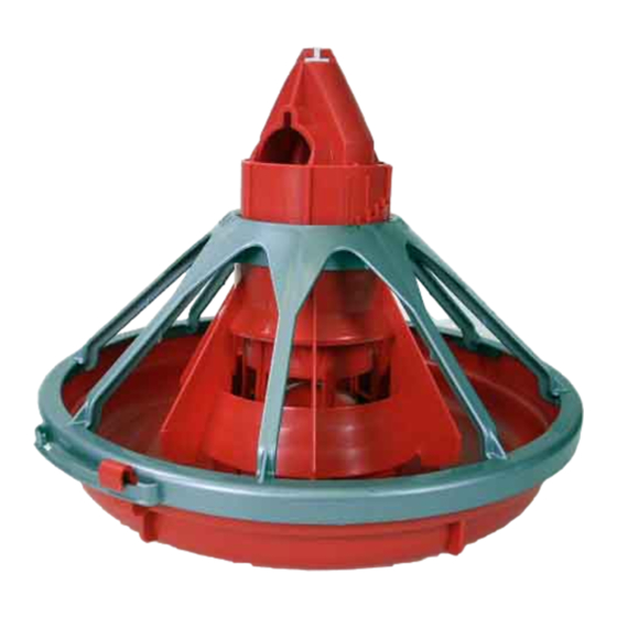
Pan breeder feeder and male feeder
Hide thumbs
Also See for G Plus:
- Installation and operator's manual (64 pages) ,
- Installation and operator's manual (62 pages)

Subscribe to Our Youtube Channel
Related Manuals for Chore-Time G Plus


Summary of Contents for Chore-Time G Plus
- Page 1 Pan Breeder Feeder and Male Feeder Installation and Operators manual Model G Plus for Male Feeder Model C2 Plus for Pan Breeder July 2023 MF513J...
-
Page 2: Chore-Time Warranty
If such a defect is found by Chore-Time to exist within the one-year period, Chore-Time will, at its option, (a) repair or replace such product free of charge, F.O.B. the factory of manufacture, or (b) refund to the original purchaser the original purchase price, in lieu of such repair or replacement. - Page 3 Warranty. Chore-Time shall not be liable for any consequential or special damage which any purchaser may suffer or claim to suffer as a result of any defect in the product. “Consequential” or special damages” as used herein include, but are not limited to, lost or damaged products or goods, costs of transportation, lost sales, lost orders, lost income, increased overhead, labor and incidental costs and operational inefficiencies.
-
Page 4: Table Of Contents
Chore-Time Warranty ........ - Page 5 Contents - continued Topic Page Installing the End Control, Boot Assembly, and Auger ........33 Auger Installation .
-
Page 6: About This Manual
About This Manual Pan Breeder Feeder About This Manual The intent of this manual is to help you in two ways. One is to follow step-by-step in the order of assembly of your product. The other way is for easy reference if you have questions in a particular area. Important: Read ALL instructions carefully before starting construction. -
Page 7: Safety Instructions
General Information The Chore-Time Pan Breeder and Male Feeding System has been designed to feed poultry. Using this equipment for any other purpose or in a way not within the operating recommendations specified in this manual will void the warranty and may cause personal injury. -
Page 8: Manufacturer's Recommendations: Birds Per Pan
* NOTICE: The above Manufacturer’s recommendations do not constitute a product warranty and are in no way to be considered as a guarantee of performance for poultry production. In addition, the above information in no way alters or revises the terms and conditions of any applicable Chore-Time manufacturer’s warranty. MF513J... -
Page 9: Planning The Floor Feeding System
Pan Breeder Feeder Planning the Floor Feeding System Planning the Floor Feeding System 1. Select the House Layout. Figure 1.Component location diagram for systems up to 400 feet [122 m]. A. Systems with line lengths over 400’ [122 m] should be split in the center, as shown in Figure 2. This will reduce auger running time and eliminate the need for Mid-Line Controls for partial house brooding. -
Page 10: General Installation Information
The Male Feeder use the Model G Plus breeder pan. The male feeder is available in nine foot 1 and 2 hole. The 9 foot tubes utilize the 348 rpm gearhead delivering 17# of feed per minute, also available is a 12 foot 3 hole feeder. -
Page 11: Installing The Suspension System
Pan Breeder Feeder Installing the Suspension System B. For systems over 350' [107 m] Figure 4. Suspension for systems over 350’ [107 m] 2. Locate the Power Lift Winch. The Power Lift Winch requires a support that will span, in a wood frame house at least 3 rafters, and in a steel frame house at least 2 rafters. -
Page 12: Installing The Main Winch Cable
Adequate overhead structure must be provided to support the weight of the feeders, hoppers, power units, etc. The Suspension System is the same for the Model C2 Plus and G Plus Feeders. The type of installation required depends on the feeder line length. -
Page 13: Screw Hook Installation
Screw Hook Installation The recommended distance between the 1) 3/16" [5 mm] drops for the Model C2 Plus & G Plus is 8’ Main Winch Cable 2) 3/32" [2 mm] [2.4 m] on center. Do not exceed 10’ [3 m] Drop Cable spacing on drop lines. -
Page 14: Ceiling Hook Installation
Installing the Suspension System Pan Breeder Feeder Ceiling Hook Installation The ceiling hook may be used in a variety of installations. Depending on your ceiling or rafter type, install the Ceiling Hooks as shown. Steel Truss Installations 2) Cable Travel 1) Secure Ceiling Hook to truss using self-drilling screws through opposite holes... -
Page 15: Drop Installation
Pan Breeder Feeder Installing the Suspension System Drop Installation Refer to Figure 12. on page 13. 1. Attach a 3004 Pulley to each hook. 2. Thread the end of the 3/32" or 1/8" cable through the pulley toward the winch. Clamp this end to the 3/16" winch cable about 6"... -
Page 16: Power Winch Installation
Pan Breeder Feeder Power Winch Installation When the 2883 Power Winch is used as an electric winch, the Input Shaft Assembly must be changed, as shown in Figure 19.. Note: If the Winch has already been installed, make sure there is no load on the Winch before attempting to change the Input Shaft Assembly. - Page 17 Pan Breeder Feeder Item Description Item Description Power Unit 5/16-18 x 3/4" Bolt Winch Winch Bracket 1/4-20 Sock Hd Bolt and Locknut Supplied 3/8-16 x 1" Bolt Heavy Duty Input Shaft 5/16-18 x 2-1/2" Bolt Install Spacer between Power Unit Bracket Cable Hook Flanges and Winch Bracket.
-
Page 18: Drop Installation
Pan Breeder Feeder 11. Turn the winch drum one full revolution. Guide the cable against the flange at the bottom of the winch drum. The cable must not wrap over itself on the drum, but should be wrapped as close as possible to each previous wrap. -
Page 19: Winch Control
Pan Breeder Feeder Winch Control Winch Control The Winch Control is designed to automatically lower feeder or water lines at a preset times on the time clock or manually. The Winch Control is not designed to automatically raise feeder or waterer lines. Installation Mount the Winch Control in a convenient location within view of the lines to be lowered. -
Page 20: Hopper Assembly Procedure
Loosely, assemble the 200# Hopper Side Panels, as shown in Figure 23, using 1/4-20 bolts and 1/4-20 hex nuts (supplied in Hardware Package). The Hopper should be assembled so that the "CHORE-TIME" decals are on opposite sides of the hopper. - Page 21 Pan Breeder Feeder Hopper Assembly Procedure Item Description Clevis Pin and Hair Pin Cable Assembly Adjustment Bracket Hanger Bracket Figure 24. 200# Hopper Suspension components. Use cotter pins, supplied, to secure the boot to the hopper. The Hopper Cover, shown in Figure 23, is optional and must be ordered separately, if desired. Secure the half of the cover with the tube opening on the top of the hopper.
-
Page 22: Feeder Assembly Procedure
This information and assembly only applies to Model C2 Plus installations. Chore-Time recommends building an assembly box to aid in assembling the Model C2 Plus feeders. To build the assembly box for the C2 Plus Feeder, use a 16" (406 mm) square piece of plywood and four 14-1/2"... -
Page 23: Pan Assembly Procedure
Pan Breeder Feeder Feeder Assembly Procedure 3. Remove the grill. Use a 7/8" (22 mm) spade bit to drill a hole at each strut location, as shown in Figure 26. 4. Use a sabre saw to cut along the inside circle, between the 7/8" holes, see figure 26. 5. -
Page 24: Feeder Line Assembly & Suspension
Feeder Line Assembly & Suspension Pan Breeder Feeder The Feeder Assemblies will be installed on the auger tubes in the Feeder Line Installation section. Description Model C2 Plus Pan Hinge Hook Hinge Lip Support Cone Figure 28. C2 Pan Assembly Feeder Line Assembly &... - Page 25 Pan Breeder Feeder Feeder Line Assembly & Suspension 4) Standard Tube 5) Control Tube 3) Feed Hopper 2) Direction of Feed Flow 2) Direction of Feed Flow 1) End Control 5) Control Tube 4) Standard Tube 4) Standard Tube 1255-123 3/2001 Figure 30.
- Page 26 Feeder Line Assembly & Suspension Pan Breeder Feeder 6. Install Adjustment Leveler within 6" (152 mm) of feeder line. Figure 34 shows the proper cable routing around the Adjustment Leveler. 7. Raise the feeder line to a convenient working height. 8.
-
Page 27: Indexing Chart For Pan Breeder Feeders
Pan Breeder Feeder Feeder Line Assembly & Suspension Indexing Chart for Pan Breeder Feeders For Systems using 9’ (2.7 m) Auger Tube and 696 RPM Power Units Number of Tubes MF513J... -
Page 28: For Systems Using 12' (3.6 M) Auger Tube And 696 Rpm Power Units
Feeder Line Assembly & Suspension Pan Breeder Feeder For Systems using 12’ (3.6 m) Auger Tube and 696 RPM Power Units Number of Tubes MF513J... -
Page 29: Indexing The Male Feeder
Pan Breeder Feeder Feeder Line Assembly & Suspension Indexing the Male Feeder 1. Beginning at the hopper, use a marker to number the feeder tubes. Begin with tube #1 at the hopper, then #2, #3, and do on, continuing until each tube in the line is marked. 2. -
Page 30: Indexing Chart For Male Feeders
Feeder Line Assembly & Suspension Pan Breeder Feeder Indexing Chart for Male Feeders For Systems using 9’ (2.7 m) Auger Tube and 348 RPM Power Units Number of Tubes MF513J... -
Page 31: For Systems Using 12' (3.6M) Auger Tube And 696 Rpm Power Units
Pan Breeder Feeder Feeder Line Assembly & Suspension For Systems using 12’ (3.6m) Auger Tube and 696 RPM Power Units Number of Tubes MF513J... -
Page 32: Model C2 Plus Feeder Lock Installation
Feeder Line Assembly & Suspension Pan Breeder Feeder Model C2 Plus Feeder Lock Installation The Model C2 Plus Feeder Lock is designed for pullet operations to prevent the feeders from swinging on the auger tubes. Note: The seam of auger tube and hardware for the Lock must be on opposite sides as shown. Otherwise an interference will occur. -
Page 33: Installing The End Control, Boot Assembly, And Auger
Pan Breeder Feeder Installing the End Control, Boot Assembly, and Auger The End Control Unit must be at least 10 feet [3 m] from the end of the building to allow birds access around the end of the feeder line. 1. -
Page 34: Auger Installation
Pan Breeder Feeder Auger Installation Note: Use extreme caution when working with the auger. The auger is under tension and may spring causing personal injury. Wear protective clothing, gloves, and safety glasses when working with the auger. BE CAREFUL WHEN WORKING WITH THE AUGER! Manboot 3/98... - Page 35 Pan Breeder Feeder 4. Slide the Drive Tube and flat washer over the output shaft on the Power Unit, as shown in Figure 43. 5. Continue installing auger until the auger reaches the Control Unit end of the feeder line. 6.
- Page 36 3) to length. Slide the wires from the end control through the Flex Conduit (item 3). Install the Flex Conduit (item 3) in the connectors. Connect the wires to the Feed Line Motor (item 2). CHORE-TIME EQUIPMENT A DIVISION OF CTB INC.
- Page 37 Pan Breeder Feeder Use a hacksaw or bolt cutters to cut the auger at the stretched auger mark. 1) Locking Pliers 2) Use a hacksaw or bolt cutters to cut the auger 4) Boot under Feed Hopper 3) Pull an extra 8" [200 mm] of auger (minimum) 1255-95 9/2000 to allow for Anchor and Bearing Installation Figure 46.
-
Page 38: Auger Brazing
Pan Breeder Feeder Auger Brazing The auger should be brazed if it is necessary to splice or lengthen it. A bronze, flux coated rod is recommended. The ends of the auger should butt against each other, DO NOT THREAD INSIDE EACH OTHER. See Figure 48.Figure 48. -
Page 39: Anti-Roost Installation
Pan Breeder Feeder Anti-Roost Installation 1. Unroll the bulk anti-roost cable. Note: If the cable is unrolled as shown in Figure 49, taking 5 loops of the coil with one hand, then changing hands to remove 5 loops as it is unrolled, it will lie flat during installation. - Page 40 Pan Breeder Feeder 2) Clamp with Anti-Roost Bracket and Insulator 5) Wire Form 4) Spring should be Stretched 3) Insulator 3/4" to 1" [19 mm to 25 mm] 1) Clamp 1255-90 9/2000 Figure 52. Anti-Roost Installation at the Control Unit 11.
- Page 41 Pan Breeder Feeder 3) Anti-Roost Wire 2) Insulated Charger Wire 1) Line Charger 1255-92 9/2000 Figure 54. Line Charger Installation 12. The anti-roost system must be on a separate electrical circuit, allowing the system to be disconnected by a switch near the door. Remember, the anti-roost system should be grounded through the poultry trainer.
-
Page 42: Feeder Management
Raise the feeder as the birds grow. This will automatically close the feed windows, unless they are locked open. Chore-Time recommends opening the feed windows in the pans for the first 5 to 10 days, for broilers. Open the feed windows in the pans for the first 10 to 14 days, for turkeys. The feeders will need to be operated at least twice a day for the first 5 days, thereafter pans may need to be resupplied 3 times a day or as birds eat feed level down. -
Page 43: Maintenance
Maintenance Maintenance Floor Feeding System Maintenance The Model C2 Plus and Model G Plus Feeders require minimum maintenance. However, a routine periodic inspection of the equipment will prevent unnecessary problems. Maintenance should be done by a qualified technician. ALWAYS DISCONNECT POWER TO THE SYSTEM WHEN SERVICING OR MAINTAINING THE EQUIPMENT. -
Page 44: Mechanical Switch Adjustment Procedure For Control Units
Maintenance Pan Breeder Feeder Mechanical Switch Adjustment procedure for Control Units Refer to Figure 56. 1) Adjustment Nut A. Turn the adjustment nut counter- clockwise until the switch clicks. B. Turn the adjustment nut clockwise until the switch clicks. C. Turn the adjustment nut counter- clockwise 3/4 turn. -
Page 45: Power Lift Winch Maintenance
Pan Breeder Feeder Maintenance Disconnect power to the system to prevent accidentally starting the system. If the system must be disassembled, extreme caution must be used to prevent injury from springing auger. Refer to Figure 58. 1. Disconnect power to the entire system. 2. -
Page 46: Trouble Shooting The Floor Feeding System
Trouble Shooting the Floor Feeding System Pan Breeder Feeder Trouble Shooting the Floor Feeding System ALWAYS DISCONNECT POWER TO THE SYSTEM WHEN SERVICING OR MAINTAINING THE EQUIPMENT. FAILURE TO DISCONNECT POWER MAY CAUSE INJURY OR DEATH. Service and maintenance work should be done by a qualified technician only. -
Page 47: Wiring Diagrams
Pan Breeder Feeder Wiring Diagrams Wiring Diagrams Winch Control Wiring Diagram with 29820-3 Tower Limit Switch 37215 MULTI-LIFT Winch with 34812 Winch Control and 29820-3 Tower Limit Switch 14560 or 14580 Electric Power Winch with 34812 Winch Control and 29820-3 Tower Limit Switch Winch Control Wiring Diagram with 39464 Limit Switch 37215 MULTI-LIFT with 34812 Winch Control and 39464 Limit Switch MF513J... -
Page 48: Male Feeder System Wiring Diagrams: Single Phase(Ø)
Wiring Diagrams Pan Breeder Feeder Male Feeder System Wiring Diagrams: Single Phase(Ø) Single Phase(Ø)Wiring Diagram Single Phase(Ø) Wiring Diagram: w/Motor Starter MF513J... -
Page 49: Male Feeder System Wiring Diagrams: Three Phase(Ø)
Pan Breeder Feeder Wiring Diagrams Male Feeder System Wiring Diagrams: Three Phase(Ø) Three Phase(Ø) Wiring Diagram: 220/230 V Three Phase(Ø) Wiring Diagram: 380/415 V MF513J... -
Page 50: Electric Power Lift Wiring Diagram
Wiring Diagrams Pan Breeder Feeder Electric Power Lift Wiring Diagram MF513J... -
Page 51: Parts Listing
Pan Breeder Feeder Parts Listing Parts Listing Standard Breeder Pans MF513J... -
Page 52: Standard Breeder Pans With Shut-Off
Parts Listing Pan Breeder Feeder Standard Breeder Pans with Shut-Off MF513J... -
Page 53: Shallow G™ Plus Breeder Pans With Slide Shut-Off
Pan Breeder Feeder Parts Listing Shallow G™ Plus Breeder Pans with Slide Shut-Off MF513J... -
Page 54: Shallow G™ Plus Breeder Pans
Parts Listing Pan Breeder Feeder Shallow G™ Plus Breeder Pans MF513J... -
Page 55: Shallow Breeder Pans
Pan Breeder Feeder Parts Listing Shallow Breeder Pans MF513J... -
Page 56: 34812 Winch Control Parts Listing
Parts Listing Pan Breeder Feeder 34812 Winch Control Parts Listing Item Description Part No. Item Description Part No. Switch Bracket 46846 Momentary Switch 5785 Toggle Switch (DPDT) 46847 Toggle Switch 6014 Clear Lid 30859-1 Pilot Light 7044 Control Box Latch 30862 Winch Control Panel 34382... -
Page 57: 8798 Switch Assembly
Pan Breeder Feeder Parts Listing 8798 Switch Assembly Item Description Part No. 6-32 x 7/8" Rd. Hd. M.S. 1921 SPDT Actuator Switch 7114 Switch Insulation 1907-5 Switch Bracket 7068 #6 x 3/8" Slot Wash. Hd. Screw 6782 6-32 Hex Nut 8757 Switch Box 7841... -
Page 58: Mechanical End Control
Parts Listing Pan Breeder Feeder Mechanical End Control CHORE-TIME EQUIPMENT A DIVISION OF CTB INC. MILFORD, INDIANA 46542-2000 40943 MODEL C2 PLUS END CONTROL WITH WINDOW CONTACT RATINGS: 1/2 H.P. @ 115 VAC 1 H.P. @ 230 VAC 2529-660 DANGER... - Page 59 Anti-Roost Guard 2798 2798 2798 2798 Parts Package 40809 40809 40809 40809 *These items are included in the Parts Package. **Actuator Switch, Chore-Time part number 7114, is no longer available. When replacing, use 7114 Switch Replacement Kit Part Number 46678. MF513J...
-
Page 60: Sensor Plus™ End Control
Parts Listing Pan Breeder Feeder Sensor Plus™ End Control CHORE-TIME EQUIPMENT A DIVISION OF CTB INC. MILFORD, INDIANA 46542-2000 40943 MODEL C2 PLUS END CONTROL WITH WINDOW CONTACT RATINGS: 1/2 H.P. @ 115 VAC 1 H.P. @ 230 VAC 2529-660... - Page 61 Pan Breeder Feeder Parts Listing Item Description C2 Plus C2 Plus G Plus G Plus Standard Shallow Standard Shallow Part No. Part No. Part No. Part No. 42680 44880 42597 44882 Cut Sleeve 43110 43110 43110 43110 Bottom Cover 42085...
-
Page 62: Boot Assemblies
Parts Listing Pan Breeder Feeder Boot Assemblies Single: Part No. 6822 Twin: Part No. 6824 Item Description Part No. Boot Weldment (Single) 3760 Boot Weldment (Twin) 3932 Tube Clamp 24063 29373 Outlet Tube 4556 Sleeve 5648 3/16 x 1" Pin 2960-1 Bearing 2689... -
Page 63: Miscellaneous Suspension Components
Pan Breeder Feeder Parts Listing Miscellaneous Suspension Components Item Description Part No. 3/16" Cable 1213 Cable Lock 14337 Pulley with Swivel 3004 Heavy Duty Pulley Assembly 2014 Pulley 2500 3/16" Cable Clamp Screw Hook 2041 Extendable Drive Tube 47637 Pulley Assembly 28429 Ceiling Hook 28550... -
Page 64: 14580 Electric Winch Kit
Parts Listing Pan Breeder Feeder 14580 Electric Winch Kit Item Description Part No. 5/16" Flat Washer 2230 5/16-18 Nut 2148 5/16-18 x 2-1/2" Hex Hd Bolt 2753 3/8-16 x 1" Hex Hd Bolt 2555 3/8" Flat Washer 4967 3/8" Patch Lock Nut 2183 Winch Mount Assembly 24580... -
Page 65: Feeder Line Components
Pan Breeder Feeder Parts Listing Feeder Line Components Item Description Part No. Auger 6820wm Line Charger (110v) 5458 Line Charger (220v) 5459 Feeder Lock 34570 1/16" Cable 1922 1/16" Cable Clamp 1826 Spring 7551 Roll Formed Tube 12 Ft. 4 Hole Tube 6854-7 9 Ft. -
Page 66: 47687 Power Winch
Parts Listing Pan Breeder Feeder 47687 Power Winch Item Qty. Description Part No. Pawl 47687-5 Input Shaft Assembly 47687-1 Indexing Gauge Item Description Part No. Level Glass 4853 Gauge Clamp Weldment 14523 Pointer Assembly 4852 Indexing Gauge Decal 2529-207 MF513J... -
Page 67: Power Unit Assemblies
Pan Breeder Feeder Parts Listing Power Unit Assemblies 1660-21 1/2001 Item Description 3259-81 3259-84 3259-100 3259-101 3259-144 Part No. Part No. Part No. Part No. Part No. Vent Plug 3516 3516 3516 3516 3516 5/16-18 x 5/8 Hex Hd Screw 4412-1 4412-1 4412-1... - Page 68 Description of Change Was 2883 Winch 35577 Various Updated Graphics For additional parts and information, contact your nearest Chore-Time distributor or representative. Find your nearest distributor at: www.choretime.com/contacts CTB, Inc. PO Box 2000 Milford, Indiana 46542-2000 USA Phone (574) 658-4101 Email: choretime@choretime.com...
Need help?
Do you have a question about the G Plus and is the answer not in the manual?
Questions and answers