Sign In
Upload
Manuals
Brands
Canon Manuals
Booklet makers
Perfect Binder D1
Canon Perfect Binder D1 Manuals
Manuals and User Guides for Canon Perfect Binder D1. We have
6
Canon Perfect Binder D1 manuals available for free PDF download: Troubleshooting Manual, Service Manual, User Manual, Service Manual Digest
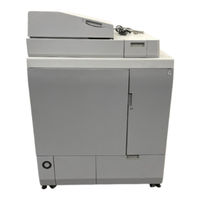
Canon Perfect Binder D1 Troubleshooting Manual (274 pages)
Brand:
Canon
| Category:
All in One Printer
| Size: 28 MB
Table of Contents
Table of Contents
3
Image Faults
5
Marks on Image Caused by Friction Due to Mini Gripper Edge (Perfect Binder- B1/D1/E1)
5
Marks on Image Caused by Friction Due to Mini Gripper Edge (Perfect Binder-C1)
11
Malfunction
17
The Spread Glue Amount Is Unstable Due to Conducting Inappropriate Procedure to Adjust the Glue Amount(Perfect Binder_A1 / Perfect Binder_C1)
17
The Spread Glue Amount Is Unstable Due to Conducting Inappropriate Procedure to Adjust the Glue Amount(Perfect Binder_B1)
27
Lines Occurring on the Trimming Side of the Books Due to the Nicked Trimming Blade (Perfect Binder_A1 / Perfect Binder_C1)
37
Lines Occurring on the Trimming Side of the Books Due to the Nicked Trimming Blade (Perfect Binder_B1 / Perfect Binder_D1)
52
Jam (Delivery Options)
67
1FA5 Jam Code Due to Wear of the Roller in the Signature Delivery Assembly(Perfect Binder-C1)
67
Error Code
68
E5B5-Xx16 Due to Damage on the Mount Portions of Dust Buffer Unit.(Perfect Binder-A1,Perfect Binder-C1)
68
E5B5-Xx16 Due to Damage on the Mount Portions of Dust Buffer Unit.(Perfect Binder-B1,Perfect Binder-D1)
76
E5B5-Xx16 Due to Fractured Hook Arm in the Waste Paper Case Assembly.(Perfect Binder-A1,Perfect Binder-C1)
84
E5B5-Xx16 Due to Fractured Hook Arm in the Waste Paper Case Assembly.(Perfect Binder-B1,Perfect Binder-D1)
110
E5B5-Xx16 Due to Sliding Failure of the Waste Stopper in the Waste Paper Case Assembly(Perfect Binder-A1,Perfect Binder-C1 )
136
E5B5-Xx16 Due to Sliding Failure of the Waste Stopper in the Waste Paper Case Assembly(Perfect Binder-B1,Perfect Binder-D1 )
144
E5B5-Xx07/ E5B5-Xx13 Errors May Occur Due to Front Cover of Booklet May be Stained and Rotation Sheet May Peel Off.(Perfect Binder_A1 / Perfect Binder_C1)
152
Rotation Sheet May Peel Off.(Perfect Binder_B1 / Perfect Binder_D1 / Perfect Binder_E1)
159
Error E5B5-Xx16 Due to the Deformation of Shutter for Waste Paper Case Assembly (Perfect Binder_A1 / Perfect Binder_C1)
165
Error E5B5-Xx16 Due to the Deformation of Shutter for Waste Paper Case Assembly (Perfect Binder_B1 / Perfect Binder_D1)
194
Measures When E5AA-000X, E5AA-800X or the Trimming Assembly Breakage Occurs (Perfect Binder-B1/D1)
223
Measures When E5AA-000X, E5AA-800X or the Trimming Assembly Breakage Occurs (Perfect Binder-C1)
238
Advertisement
Canon Perfect Binder D1 Service Manual (142 pages)
Booklet Trimmer
Brand:
Canon
| Category:
Trimmer
| Size: 17 MB
Table of Contents
Explanation of Symbols
2
Table of Contents
4
Safety Precautions
7
Notes before It Works Serving
8
Points to Note at Cleaning
8
Product Overview
9
Product Specifications
10
Names of Parts
11
External View
11
Cross Section
12
Technology
13
Basic Operation
14
Basic Operation of the Fore-Edge Trimmer
14
Communication between the Host Machine and the Fore-Edge Trimmer
15
The Fore-Edge Trimmer Control System
15
Transport Drive System
18
Overview
18
Control System
18
Fore-Edge Trim Operation
20
Preparation Stage Control
20
Infeed Section Control
22
Trim Section Control
22
Booklet Lifter and Delivery Section Control
23
Conveyor Section Control
23
Stop Control
23
Pass through Operation (Without Trimming)
24
Preparation Stage Control
24
Infeed Section Control
25
Trim Section Control
26
Booklet Lifter and Delivery Section Control
26
Conveyor Section Control
26
Stop Control
26
Detecting Jams
27
Power Source
31
208-240V Power Supply Route
31
5V/24V Power Supply Route
32
Periodical Service
34
User Maintenance
35
Maintenance and Inspection
36
Periodic Parts Replacement
36
Consumables
36
Periodic Servicing
36
Disassembly/Assembly
38
Electrical Components/Functions
39
Sensors
39
Switches
40
Motors
41
Printed Circuit Boards and Other Parts
42
Part Replacement Procedures
43
External Covers
43
Front Cover
43
Drive System
44
Infeed Unit
44
Document Feeding System
58
Electrical System
71
Adjustment
76
Service Mode
77
Home Position Calibration
77
Setting Position Check
78
Motion Test
78
Flat Belts Installing Direction
80
Lower Knife Height Adjustment
81
Upper Knife Upper Limit Sensor PI06 Height Adjustment
82
Normal Position for Stopping the Upper Knife
82
Trim Section Drive Belt Tension Adjustment
84
Adjusting the Position of Front Cover Switch SW01
85
Stopper Angle Adjustment
86
Troubleshooting
87
Trimming Problems
88
Skewed Trimming
88
The Trimmed Booklet Is Longer or Shorter than the Set Size
88
The Booklet Is Left Untrimmed, or Is Torn off
88
The Booklet Is Smeared on Its Surface
88
A Pressing Line Remains on the Booklet
88
Malfunction
89
Soiled Booklet/Stacking Fault Due to Heavy Stacking at the Conveyer Area
89
The Unbound Booklet Goes into Another Booklet on the Conveyor
89
Upgrading the Control Software
91
Overview
91
Error/Jam/Alarm
94
Error Codes
95
E0005A7-8011: Transport Hook Motor M02 Home Positioning Incompletion
95
E0005A7-8012: Transport Hook Motor M02 Remaining in Home Position
95
E0005A7-8021: Top-Bottom Guide Motor M03 Home Positioning Incompletion
96
E0005A7-8022: Top-Bottom Guide Motor M03 Remaining in Home Position
96
E0005A7-8033: Trim Section Transport Motor M04 Driver Problem
97
E0005A7-8043: Knife Motor M05 Driver Problem
97
E0005A7-8044: Upper Knife Cannot Detect Upper Limit Position in One Stroke
97
E0005A7-8051: Stopper Move Motor M06 Home Positioning Incompletion
97
E0005A7-8052: Stopper Move Motor M06 Remaining in Home Position
98
E0005A7-8055: Stopper EEPROM Error
98
E0005A7-8061: Conveyor Delivery Roller Positioning Motor M08 Home Positioning Incompletion
98
E0005A7-8062: Conveyor Delivery Roller Positioning Motor M08 Remaining in Home Position
99
E0005A7-8065: Conveyor Delivery Roller EEPROM Error
100
E0005A7-8073: Main Drive Motor M10 Driver Problem
100
E0005A7-8088: Two-Knife Booklet Trimmer Communication Command Retransfer Processing Error
100
Jam Code
101
11C7: the Booklet Jam Occurs Freguently in Entrance of Trim Section
101
11CF: the Booklet Jam Occurs Freguently in Delivery Section
101
Installation
102
Before Installation
103
Checking the Included Parts
103
Product Name
103
Selecting the Installation Site
104
Unpacking Procedure
105
Installation Procedure
111
Preparing the Booklet Trimmer
111
Preparing the Stitcher
113
Connecting to the Stitcher
114
Checking the Height and Tilt
116
Adjustments
119
Adjusting the Height and Tilt
119
Installation after Check/Adjustment
123
Appendices
133
Service Tools
134
Solvents
134
Accessory Tools
134
Timing Chart
135
Trimming Operation
135
Pass through (Without Trimming) Operation
136
Circuit Diagrams
137
Abbreviations for Signals and Wire Color
137
120-127VAC / 220-240VAC Circuit Diagram
138
24 VDC Circuit Diagram
139
I/O Circuit Diagram
140
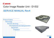
Canon Perfect Binder D1 Service Manual (99 pages)
Color Image Reader Unit
Brand:
Canon
| Category:
Card Reader
| Size: 13 MB
Table of Contents
Table of Contents
5
Safety Precautions
8
Notes before It Works Serving
9
1 Product Outline
10
Features (Reader)
10
Specifications (Reader)
10
Names of Parts (Reader)
10
External View
12
Cross Section
12
Major Components
13
Reader Relay PCB
13
Specifications (DADF)
14
Names of Parts (DADF)
15
External View
15
Cross Section
15
2 Technology
16
Technology (Reader)
16
Basic Sequence
17
Basic Sequence at Power-On
17
Basic Sequence at Start Key on (Book Mode/1 Original)
17
Basic Sequence at Start Key on (ADF Mode/1 Original)
17
Controls (Reader)
18
Controlling the Scanner Drive System
18
CCD
19
Enlargement/Reduction
21
Detecting the Size of Originals
21
Dirt Sensor Control
23
Image Processing
25
Reader Heater Control
27
Basic Configuration (DADF)
28
Component Configuration
28
Outline of Electric Circuits
28
Sensor Layout
29
Drive Configuration
29
Outline of Operation Modes
30
Outline
30
Forward Pickup/Delivery Operation
30
Forward Pickup/Reverse Delivery Operation
31
Controls (DADF)
33
Document Detection
33
Outline
33
Initial Document Size Detection
34
Detecting Jams
34
Power Supply
35
Fan
35
3 Periodic Servicing Work of Service (Reader)
37
List of Work for Scheduled Servicing
37
Action to Take When Replacing Parts
37
Consumables
37
Service Precautions
37
Work of Service (DADF)
38
When Replacing the Parts
38
Periodic Servicing
38
List of Work for Scheduled Servicing (DADF)
39
4 Parts Replacement and Cleaning Procedure
40
List of Parts(Reader)
40
External Covers
41
Main Units
41
List of Clutchs, Solenoids, Motors, Fans, Pcbs
41
List of Sensors
41
Consumable Parts Requiring Periodic Replacement and Cleaning Points
41
External Covers(Reader)
42
Removing the Reader Left Cover
42
Removing the Reader Front Cover
42
Removing the Reader Right Cover
42
Removing the Reader Rear Cover
43
Main Units/Parts (Reader)
44
Removing the CCD Unit
44
Action to Take after Replacing the CCD Unit
46
Removing the Platen Glass
47
Action to Take after Replacing the Platen Glass
47
Removing the ADF Scan Glass
48
Action to Take after Replacing the ADF Scan Glass
48
List of Parts(DADF)
50
External Covers
50
Consumable Parts Requiring Periodic Replacement and Cleaning Points
50
List of Clutchs, Solenoids, Motors, Fans, Pcbs
51
List of Sensors
51
External Covers (DADF)
52
Removing the Front Cover
52
Removing the Rear Cover
52
Removing the Feeder Cover
53
Main Units (DADF)
54
Removing the Feed Unit
54
Consumable Parts Requiring Periodic Replacement and Cleaning Points (DADF)
55
Removing the Pickup Roller Unit
55
Removing the Separation Pad
56
Replacing the Stamp
56
Exchanging the Feed Roller Guide
57
Clutch Solenoid Motor Fan PCB (DADF)
58
Removing the ADF Motor(M1)
58
Removing the Release Motor(M2)
58
Removing the Pressurization Solenoid(SL1)
59
Pickup Clutch/Registration Clutch(CL1/CL2)
59
Removing the ADF Driver PCB
60
Removing the LED PCB
61
Removing the Fan
61
Removing the Sensor(SR1,SR2,SR3)
62
Removing the Timing Sensor(SR4)
66
Removing the Document Set Sensor(SR5)
66
Removing the Cover Open/Closed Sensor(SR6)
66
Removing the Last Document Detection Sensor(SR7)
66
Removing the Document Length Sensor(SR8,SR9)
67
Removing the Release Motor HP Sensor(SR11)
67
5 Adjustment
69
Image Position Adjustment(Reader)
70
Leading Edge Non-Image Width
70
Left Non-Image Width
70
Overview (DADF)
71
Adjustment Method (DADF)
71
Adjusting the Height
71
Pre-Check
71
Checking the Left Hinge Height
72
Adjustment Procedure
73
Adjust the Height of the Left Hinge
73
Check the Height of the Right Hinge
73
Adjust the Height of the Right Hinge
73
Adjusting the Perpendicularity
74
Adjusting the Read Position
75
Adjusting the Horizontal Registration
75
Adjusting the Trailing Edge Registration
75
Adjusting the Magnification
75
Adjusting the White Level
76
6 Installation
77
How to Utilize this Installation Procedure
78
Illustrations Used in this Procedure
78
Descriptions Used in this Procedure
78
When Using the Contained Parts (Bundled Components in the Shipping Carton)
78
Symbols in the Illustration
78
Caution During Installation
79
Turning off the Host Machine Power
79
Checking the Contents
80
Installation Procedure
81
Operation Check
92
Appendix
93
Service Tools
93
Solvents and Oils
94
Special Tools
94
General Circuit Diagram(DADF)
95
General Circuit Diagram
95
General Circuit Diagram(Reader)
96
General Circuit Diagram
96
Signal Name List(Reader)
97
Signal Name List(DADF)
98
Signal Name List
98
Advertisement
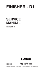
Canon Perfect Binder D1 Service Manual (188 pages)
Brand:
Canon
| Category:
Power Tool
| Size: 2 MB
Table of Contents
Table of Contents
5
Chapter 1 General Description
9
Features
9
Specifications
10
Cross Section
12
Operating the Finisher
13
Removing Jams from the Finisher
13
Removing Jams in Sort, Group, or Staple Sort Mode
15
Replacing the Staple Cartridge
18
Removing Staple Jams in the Stapler Unit
21
Maintenance by the User
23
Basic Operations
27
Specifications
27
Outline of Electrial Circuitry
28
Inputs to and Outputs from the Finisher Controller PCB
29
Feeding/Drive System
40
Outline
40
Feeding/Delivery
45
Job Offset
48
Releasing the Knurled Belt
55
Buffer Path
60
Controlling the Paddle
65
Controlling the Tray Auxiliary Plate
66
Stapling
68
Tray Movement
76
Fans
80
Power Supply
82
Detecting Jams
85
Processing Tray Unit
101
Tray B Unit
109
Knurled Belt
116
Knurled Belt Releasing Unit
116
Knurled Belt
118
Buffer Roller Unit
119
Stapler Unit
123
Pcbs
130
Chapter 4 Maintenance and Servicing
131
Parts
131
Consumables and Durables
133
Chapter 5 Troubleshooting
137
Adjustment
137
Electrical System
137
Arrangement of Electrical Parts
150
Sensors
150
Microswitches
152
Motors
154
Solenoids
156
Pcbs
158
Fans
160
Light-Emitting Diodes and Check Pins by PCB
161
Troubleshooting
166
Self Diagnosis
174
Alarms
176
Appendix
177
General Circuit Diagram
177
Solvents and Oils List
185
canon Perfect Binder D1 Service Manual Digest (28 pages)
staple finisher and finisher additional tray
Brand:
canon
| Category:
Finishers
| Size: 2 MB
Table of Contents
Table of Contents
1
Safety Precautions
6
Notes before It Works Serving
7
Periodic Servicing
8
Periodic Service Works(Finisher)
8
Periodical Service
9
Adjustment
10
Basic Adjustment
10
Adjustment Item
11
Adjustment
11
Counter
12
Function Setting
12
Adjustment at Time of Parts Replacement(Finisher)
13
Action on Replacing the Finisher Controller PCB
13
Measures at Time of Parts Replacement
13
Parts Placement Diagram
14
List of Parts(Finisher)
14
Motors/Switches/Solenoids
15
Sensors1
15
Sensors2
16
Pcbs
16
Product Outline
17
Features(Finisher)
17
Specifications(Finisher)
17
Names of Parts(Finisher)
17
External View 1
21
Cross Section
21
Basic Configuration(Finisher)
22
Outline of Basic Operation
22
Non-Sort Operation
22
Offset Operation
22
Stapling Operation
23
General Circuit Diagram
25
Service Tools
25
Solvents and Oils
26
Special Tools
26
General Circuit Diagram(Finisher)
27
General Circuit Diagram(Additional Tray)
28
Canon Perfect Binder D1 User Manual (28 pages)
Booklet Trimmer
Brand:
Canon
| Category:
Booklet makers
| Size: 3 MB
Table of Contents
Important Information
4
Safe Use of Machine
5
Operating Safety Precautions
5
Caution Label Locations
6
Fcc Notices
6
Table of Contents
7
Before You Begin
8
Machine Description
9
Section Descriptions
10
Infeed Section
10
Trimmer Booklet Waste Tray
11
Trim Section
11
Booklet Lifter Section 1
12
Booklet Lifter Section 2
12
Booklet Lifter Section 2
13
Delivery Tray
14
Conveyor Section
14
Operation While Trimming
16
Operating Procedures
16
Trimmer Setup
17
Operation While Trimming
18
Troubleshooting
20
Error Messages
21
Service Call Error
21
Error Message Chart
22
Jam in Booklet Lifter Section
23
Jam in Infeed Section
23
Clearing Paper Jams
23
Index
24
Appendix
24
Specifications
25
Index
26
Advertisement
Related Products
Canon D17-3712-251 - GL1 Camcorder - 270 KP
Canon CanoScan D1230UF
Canon D1250U2F - CanoScan USB Flatbed Scanner
Canon D1230U/D2400U
Canon PowerShot D10
Canon INON D-180
Canon imageCLASS D1320
Canon imageCLASS D1350
Canon imageCLASS D1370
Canon imageCLASS D1120
Canon Categories
Printer
Digital Camera
All in One Printer
Camcorder
Scanner
More Canon Manuals
Login
Sign In
OR
Sign in with Facebook
Sign in with Google
Upload manual
Upload from disk
Upload from URL