Sign In
Upload
Manuals
Brands
Baby Lock Manuals
Sewing Machine
BLMY
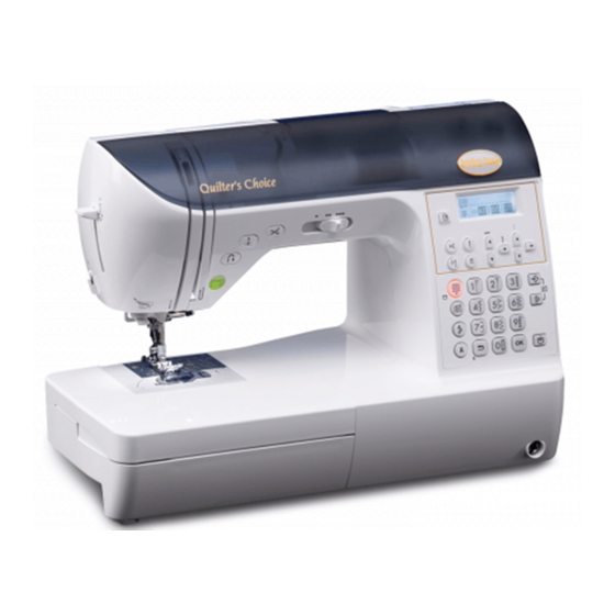
Baby Lock BLMY Sewing Machine Manuals
Manuals and User Guides for Baby Lock BLMY Sewing Machine. We have
1
Baby Lock BLMY Sewing Machine manual available for free PDF download: Service Manual
Baby Lock BLMY Service Manual (226 pages)
Computerized Sewing Machine
Brand:
Baby Lock
| Category:
Sewing Machine
| Size: 12 MB
Table of Contents
Table of Contents
5
Main Mechanisms
13
Driveline
14
Positions of Electronic Components
15
Control System Block Diagram
16
Operation of Other Electronic Components
17
Using the Threader
18
2 Disassembly
20
Main Unit Main Parts
22
Electrical Parts and Motors
31
Thread Tension Mechanism
38
PF-F SW Assy. Removal
39
Thread Guide Shutter Removal
40
Thread Guide Removal
41
Thread Take up Spring Removal
42
Bobbin Winder Mechanism
43
Bobbin Winder Cover Removal
44
Bobbin Winder Mechanism
44
BW Holder Supporter Removal
45
Cutter Assy. Location Diagram
47
Leading Guide Removal
47
Rotary Hook Drive Mechanism
47
Lower Shaft a Assy. Removal
48
Needle Bar, Presser Mechanism
49
Upper Shaft Mechanism
50
Upper Shaft Removal
50
Needle-Presser Module Removal
51
Plate Spring Removal
52
Needle-Presser Module
53
Modules Needle-Presser Module
54
BH Switch Assy. Removal
54
Spring-Z Removal
55
Spring Guard Removal
56
Release Lever Removal
57
Needle Bar Assy. Removal
58
Lever a Spring Removal
59
Lever AB Assy. Disassembly
60
Threader Hook Assy. Disassembly
61
Thread Take-Up Assy. Removal
62
Remove the Z Zigzag Cam
63
T Cam Removal
64
Thread Take-Up Lever Link Removal
65
Feed and Bobbin Module
66
Feed and Bobbin Module
67
Needle Plate a Removal
67
F Pulse Motor Assembly Removal
68
Feed Bar Spring Removal
69
Lower Shaft B Assy. Removal
70
Shaft Stopper Plate Removal
71
Feed Arm Assy. Disassembly
72
Feed Adjuster Assembly Removal
73
Drop Assy. Removal
74
Thread Cutter Module
75
Thread Cutter Module
76
Thread Cutter Frame Assembly Removal
76
Cutter Holder Assembly Removal
77
Thread Cutter Lever Assy. Removal
78
3 Assembly
80
Needle Bar, Presser Mechanism / Upper Shaft Mechanism
81
Main Unit Needle Bar, Presser Mechanism / Upper Shaft Mechanism
82
Plate Spring Attachment
82
Needle-Presser Module Attachment
83
Pulley Attachment
84
Connecting the Needle-Presser Module and Upper Shaft
85
Rotary Hook Drive Mechanism / Feed and Bobbin Mechanism /Cutter Assy
86
Assembling the Lower Shaft a Assembly
87
Lower Shaft a Attachment
88
Thread Cutter Module Attachment
89
Bobbin Winder Mechanism
90
Bobbin Winder Mechanism
91
Bobbin Winder Shaft Stopper (Bobbin Winder Assembly Holder) Assembly
91
BW Holder Supporter Attachment
92
Bobbin Winder Cover Attachment
93
Thread Tension Mechanism
94
Thread Tension Mechanism
95
Spring Tape Attachment
95
Thread Take up Spring Attachment
96
Tension Disk Attachment
97
Thread Tension Gear Attachment
98
Tension Releaser Link Attachment
99
Thread Release Holder Assy. Attachment
100
Thread Guide Cover Assembly
101
Electrical Parts and Motors
102
Electrical Parts and Motors
103
NP PCB Assy. Attachment
103
Side Feed Mechanism Assembly
104
Side Feed Mechanism Attachment
105
Base Plate Rubber Attachment
106
Power Supply Unit F Attachment
107
Lead Assembly (BH-Cable-F) Attachment
108
Main Parts
109
Handle Assembly and Attachment
110
Main Parts
110
Rear Cover Attachment
111
Front Cover Assembly (SV Keytop Attachment)
112
Front Cover Assembly (Spool Pin Attachment)
113
Operation PCB Holder Assembly Attachment
114
Operation PCB Assembly Attachment
115
Front Cover Attachment
116
Free Arm Cover Attachment
117
Face Plate Assembly
118
Accessory Table Assembly and Attachment
119
Needle-Presser Module
120
Shaft Bushing Assembly Attachment
121
Presser Bar Attachment
122
Modules Needle-Presser Module
123
Shaft Attachment
123
Z Pulse Motor Attachment
124
Z Zigzag Lever Assy. Attachment
125
Thread Take-Up Lever Assy. Attachment
126
Presser Foot Lifter Attachment
127
Threader Hook Assy. Attachment
128
Thread Guide Plate Attachment
129
Lever AB Assy. Attachment
130
Lever a Spring Attachment
131
Needle Bar Assembly
132
Needle Bar Assembly Attachment
133
Release Lever Attachment
134
Spring (for Needle Bar Supporter Assy.) Attachment
135
Presser Dial Attachment
136
Zigzag Adjusting Nut Attachment
137
Adjusting Plate Assy. Attachment
138
Feed Module
139
Feed Module
140
Drop Knob Attachment
140
Drop Assy. Attachment
141
Feed Adjuster Assembly Attachment
142
Assembling the Feed Arm Assy
143
Feed Arm Assembly Attachment
144
Shaft Stopper Plate Attachment
145
Lower Shaft B Assy. Attachment
146
Supporting Plate Spring Attachment
147
Vertical Adjusting Screw Attachment
148
Feed Bar Spring Attachment
149
Inner Rotary Hook Bracket Assy. Attachment
150
FPM Holder Assy. Attachment
151
F Gear Teeth Alignment
152
Spring Attachment (for FPM Holder Assy.)
153
Needle Plate a Assy. Attachment
154
Thread Cutter Module
155
Thread Cutter Module
156
C Pulse Motor Attachment
156
Assembling the Thread Cutter Lever Assy
157
Assembling the Thread Hook Assy
158
Sensor Holder Attachment
159
Thread Cutter Frame Assembly Attachment
160
4 Adjustment
162
Needle Curvature
163
Tip Damage to Needle
164
Starting Test Mode
165
Test Mode
166
Timing Belt Tension Adjustment
167
Motor Belt Tension Adjustment
168
Needle Bar Rise Adjustment
169
Needle Bar Height Adjustment
170
Three Point Needle Drop Adjustment
171
Needle Interference Left/Right Adjustment
172
Clearance between the Needle and the Rotary Hook Point Adjustment
173
Presser Bar Height and Parallel Adjustment
174
Fine Tension Adjustment
175
Upper Thread Tension Adjustment
176
Inner Rotary Hook (Lower Thread) Tension Adjustment
177
Feed Adjustment
178
Bobbin Winder (Uneven Bobbin Winding and Bobbin Winding Amounts) Adjustment
179
BH Lever Switch Position Adjustment
180
Forward and Back Adjustment of Needle and Presser
181
Knee Lifter Adjustment
182
Side Feed Line Adjustment
183
One-Point Pattern Adjustment
184
Left and Right Feed Dog Position Adjustment
185
Release Adjustment
186
Front/Back, Left/Right Position of Feed Dog Adjustment
187
Feed Dog Height Adjustment
188
Inner Rotary Hook Bracket Position Adjustment
189
Adjust the Needle Thread Block
190
5 Failure Investigation
192
5 Failure Investigation for Electronic Parts
192
Pattern Cannot be Selected
196
Main Motor Does Not Turn
197
Cannot Sew Pattern Well
200
Cannot Sew Button Holes Well
201
Stitch Length and Zigzag Width Cannot be Done by Manual Adjustment
202
Problems with Vertical Needle Movement and Reverse Stitching
203
Does Not Operate When the Foot Controller Is Used
204
Thread Tensioning Does Not Go Well
205
Thread Cutter Does Not Work Normally
206
LCD Display Is Not Normal
207
LCD Light Does Not Come on
208
Bobbin Winding Cannot be Done
209
The Lamp at Hand Does Not Have Light
210
Error Is Displayed
211
6 Special Instructions of Wiring
218
Needle Bar Module Wiring
219
Thred Cutter / Rotary Hook Module Wiring
221
Side Feed Mechanism Wiring
222
Main PCB Assembly Wiring
223
Front Cover Assembly Wiring
225
Advertisement
Advertisement
Related Products
Baby Lock BLMPR2
Baby Lock BLMA2
Baby Lock BLMJZ-2
Baby Lock BLMAG
Baby Lock Model BLCS
Baby Lock imagine wave BLE3ATW
Baby Lock Molly BL30A
Baby Lock Pro-Stitcher BLPS3
Baby Lock BL450
Baby Lock BLTA2
Baby Lock Categories
Sewing Machine
Sewing Machine Accessories
PDA
Software
Accessories
More Baby Lock Manuals
Login
Sign In
OR
Sign in with Facebook
Sign in with Google
Upload manual
Upload from disk
Upload from URL