Sign In
Upload
Manuals
Brands
Allen-Bradley Manuals
Measuring Instruments
1756-CFM
Allen-Bradley 1756-CFM Manuals
Manuals and User Guides for Allen-Bradley 1756-CFM. We have
1
Allen-Bradley 1756-CFM manual available for free PDF download: User Manual
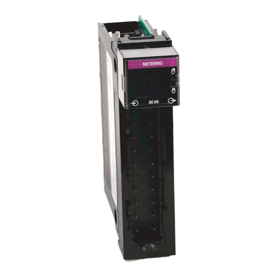
Allen-Bradley 1756-CFM User Manual (150 pages)
ControlLogix Configurable Flowmeter Module
Brand:
Allen-Bradley
| Category:
Measuring Instruments
| Size: 2.96 MB
Table of Contents
Table of Contents
3
Additional Resources
7
Preface
7
Summary of Changes
7
Who Should Use this Manual
7
Chapter 1 Using a Controllogix CFM Module
9
What this Chapter Contains
9
Module Features
10
Physical Features
10
Typical Applications
11
Understanding Module Input Capabilities
12
Understanding Module Output Capabilities
12
Using Module Identification and Status Information
13
What this Chapter Contains
15
Chapter 2
16
Ownership
16
Using Rsnetworx and the Programming Software
17
CFM Modules in Local Chassis
17
CFM Modules in Remote Chassis
17
Connections
18
Direct Connections
18
Listen-Only Connections
18
Configurable Flowmeter Modules in a Local Chassis
19
Requested Packet Interval (RPI)
19
Configurable Flowmeter Modules in a Remote Chassis
20
Chapter 3 Understanding General Module Features
21
Removal and Insertion under Power (RIUP)
21
Module Fault Reporting
21
Fully Software Configurable
22
Electronic Keying
22
Producer/Consumer Model
29
Module Status Information
29
Configurable Flowmetering Channels
29
Flowmeter Inputs
29
Gate Inputs
30
User-Defined Preset and Rollover Values
30
Current-Sourcing Outputs
30
What this Chapter Contains
21
Choosing an Operational Mode
30
Operating in High Resolution Frequency Mode
31
Terminal Usage in High Resolution Frequency Mode
32
Output Operation in High Resolution Frequency Mode
32
Module Features Used in High Resolution Frequency Mode
32
Alarms in High Resolution Frequency Mode
34
Sample Configuration for High Resolution Frequency Mode
34
Operating in Totalizer Mode
35
Nonresettable Totalizer
35
Terminal Usage in Totalizer Mode
35
Output Operation in Totalizer Mode
35
Using the Totalizer Mode Prover Function
36
Using a Prover
37
Features Available with the Prover Function
38
Alarms with the Prover Function
43
Sample Configuration for Totalizer Mode Prover Function
43
Using the Totalizer Mode Filler Function
44
Trickle Function for Totalizer Mode
45
Totalizer Mode Filler Function
46
Alarms with the Filler Function
51
Sample Configuration for Totalizer Mode Filler Function
51
Configurable Output Behaviors
52
How to Enable Output Behavior Configuration
53
Install the Configurable Flowmeter Module
55
Chapter 4
56
Power Requirements
56
Installing the Module
57
Keying the Removable Terminal Block/Interface Module
58
Key the Module
58
Key the RTB/IFM
58
Wiring the Removable Terminal Block
59
Connect Grounded End of the Cable
59
Connect Ungrounded End of the Cable
60
Connect Wires to the Rtbs
60
Wiring the Module
61
Standard Flowmeter Wiring Example
61
Standard Prover/Detector Wiring Example 1
62
Standard Prover/Detector Wiring Example 2
63
Standard Output Wiring Example
64
Assembling the Removable Terminal Block and Housing
65
Installing the Removable Terminal Block on the Module
65
Removing the Removable Terminal Block from the Module
66
Removing the Module
67
Chapter 5
69
Using this Chapter
69
What this Chapter Contains
69
Overview of the Configuration Process
70
Creating a New Module
72
Communication Format
74
Electronic Keying
75
Using the Default Configuration
75
Altering the Default Configuration
76
Accessing the Tags
77
Changing Configuration Information at the Tags
78
Configurable Features
78
Downloading Configuration Data
79
Changing Configuration During CFM Module Operation
80
Using Ladder Logic
80
Using Message Instructions
81
Processing Real-Time Control and Module Services
81
One Service Performed Per Instruction
81
Creating a New Tag
82
Enter Message Configuration
84
Configuring CFM Modules in a Remote Chassis
86
Sample Configuration for High Resolution Frequency Mode
88
Sample Configuration for Totalizer Mode Prover Function
91
Sample Configuration for Totalizer Mode Filler Function
96
Digital Filter
101
Appendix A
103
Using the Status Indicators
103
What this Appendix Contains
103
Using Programming Software to Troubleshoot Your Module
104
Determining Fault Type
105
Using Error Codes
105
Configuration Structure
107
Appendix B
112
Input Tags
112
Output Tags
115
Input Circuits
119
Flowmeter Inputs
119
Gate Inputs
120
What this Appendix Contains
119
Output Circuits
122
Discrete Outputs
122
Appendix D Frequency Accuracy in High Resolution Frequency Mode
125
Calculate Frequency Accuracy
125
Frequency Accuracy in Totalizer Mode
127
Calculate Frequency Accuracy
127
Appendix E
130
Add the 1756-Generic Profile to the Program
130
Program
131
Specify the Configurable On/Off Behavior
133
Configure the 1756-CFM for Use in a New Application
130
Configure a 1756-CFM Module for Use in an Existing Application
134
Add the 1756-Generic Profile to the Program
134
Program
135
Specify the Configurable On/Off Behavior
137
Glossary
139
Index
141
Advertisement
Advertisement
Related Products
Allen-Bradley Dynamix 1444 Series
Allen-Bradley 1444-DYN04-01RA
Allen-Bradley 1444-TSCX02-02RB
Allen-Bradley 1444-RELX00-04RB
Allen-Bradley 1444-AOFX00-04RB
Allen-Bradley 1756-CN2/B
Allen-Bradley 1756-CNBR/E
Allen-Bradley 1756-CN2R/B
Allen-Bradley ControlLogix 1756-CNB
Allen-Bradley 1756-CND: 1756-CNE
Allen-Bradley Categories
Control Unit
Controller
I/O Systems
Power Supply
Switch
More Allen-Bradley Manuals
Login
Sign In
OR
Sign in with Facebook
Sign in with Google
Upload manual
Upload from disk
Upload from URL