Sign In
Upload
Manuals
Brands
Agilent Technologies Manuals
Multimeter
U1253B
Agilent Technologies U1253B Manuals
Manuals and User Guides for Agilent Technologies U1253B. We have
4
Agilent Technologies U1253B manuals available for free PDF download: User's Manual And Service Manual, User's And Service Manual, Quick Start Manual
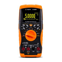
Agilent Technologies U1253B User's Manual And Service Manual (225 pages)
True RMS OLED Multimeter
Brand:
Agilent Technologies
| Category:
Multimeter
| Size: 5.56 MB
Table of Contents
Trademark Acknowledgements
2
Safety Symbols
3
General Safety Information
4
Environmental Conditions
6
In this Guide
9
Table of Contents
11
1 Getting Started
24
Introducing the Agilent U1253B True RMS OLED Multimeter
24
Check the Shipment
26
Adjusting the Tilt-Stand
27
Figure 1-3 Tilt-Stand at Hanging Position
29
The Front Panel at a Glance
30
Figure 1-4 U1253B Front Panel
30
The Rear Panel at a Glance
31
Figure 1-5 Rear Panel
31
The Rotary Switch at a Glance
32
Figure 1-6 Rotary Switch
32
Table 1-1 Rotary Switch Description and Functions
32
The Keypad at a Glance
33
Figure 1-7 U1253B Keypad
33
Table 1-2 Keypad Descriptions and Functions
34
The Display at a Glance
36
Table 1-3 General Display Symbols
36
Table 1-4 Primary Display Symbols
37
Table 1-5 Secondary Display Symbols
39
Table 1-6 Analog Bar Range and Counts
41
Selecting Display with the Shift Button
42
Table 1-7 Selecting Display with the Shift Button
42
Selecting Display with the Dual Button
43
Table 1-8 Selecting Display with the Dual Button
43
Selecting Display with the Hz Button
47
Table 1-9 Selecting Display with the Hz Button
47
The Terminals at a Glance
49
Figure 1-8 Connector Terminals
49
Table 1-10 Terminal Connections for Different Measurement
50
2 Making Measurements
51
Understanding the Measurement Instructions
52
Measuring Voltage
52
2 Making Measurements
52
Table 2-1 Numerical Steps Descriptions
52
Figure 2-1 Measuring AC Voltage
53
Measuring AC Voltage
53
Figure 2-2 Measuring DC Voltage
54
Measuring DC Voltage
54
Measuring Current
55
Μa and Ma Measurement
55
Figure 2-3 Measuring Μa and Ma Current
56
Percentage Scale of 4 Ma to 20 Ma
57
Table 2-2 Percentage Scale and Measurement Range
57
Figure 2-4 Measurement Scale of 4 Ma to 20 Ma
58
A (Ampere) Measurement
59
Figure 2-5 a (Ampere) Current Measurement
59
Frequency Counter
60
Figure 2-6 Measuring Frequency
61
Measuring Resistance, Conductance, and Testing Continuity
62
Figure 2-7 Type of Display When Smart
63
Figure 2-8 Measuring Resistance
64
Figure 2-9 Resistance, Audible Continuity, and Conductance
65
Table 2-3 Audible Continuity Measurement Range
66
Figure 2-10 Short Continuity and Open Continuity Test
67
Figure 2-11 Conductance Measurement
68
Testing Diodes
69
Figure 2-12 Measuring the Forward Bias of a Diode
70
Figure 2-13 Measuring the Reverse Bias of a Diode
71
Measuring Capacitance
72
Figure 2-14 Capacitance Measurements
73
Measuring Temperature
74
Figure 2-15 Connecting the Thermal Probe into the Non-Compensation Transfer Adapter
75
Figure 2-16 Connecting the Probe with Adapter into the
75
Figure 2-17 Surface Temperature Measurement
77
Alerts and Warning During Measurement
78
Overload Alert
78
Input Warning
79
Figure 2-18 Input Terminal Warning
79
Charge Terminal Alert
80
Figure 2-19 Charge Terminal Alert
80
Dynamic Recording
81
3 Functions and Features
82
Dynamic Recording
82
Figure 3-1 Dynamic Recording Mode Operation
83
Data Hold (Trigger Hold)
84
Figure 3-2 Data Hold Mode Operation
85
Refresh Hold
86
Figure 3-3 Refresh Hold Mode Operation
87
Null (Relative)
88
Figure 3-4 Null (Relative) Mode Operation
89
Decibel Display
90
Figure 3-5 Dbm Display Mode Operation
91
Figure 3-6 Dbv Display Mode Operation
92
Ms Peak Hold
93
Figure 3-7 1 Ms Peak Hold Mode Operation
94
Data Logging
95
Manual Logging
95
Figure 3-8 Manual (Hand) Logging Mode Operation
96
Figure 3-9 Full Log
96
Interval Logging
97
Figure 3-10 Interval (Time) Logging Mode Operation
98
Reviewing Logged Data
99
Figure 3-11 Log Review Mode Operation
100
Square Wave Output
101
Table 3-1 Available Frequencies for Square Wave Output
101
Figure 3-12 Frequency Adjustment for Square Wave Output
102
Figure 3-13 Duty Cycle Adjustment for Square Wave Output
103
Figure 3-14 Pulse Width Adjustment for Square Wave Output
104
Remote Communication
105
Figure 3-15 Cable Connection for Remote Communication
105
Selecting Setup Mode
107
4 Changing the Default Settings
108
Selecting Setup Mode
108
Default Factory Settings and Available Setting Options
109
Table 4-1 Default Factory Settings and Available Setting Options for
109
Figure 4-2 Data Hold/Refresh Hold Setup
113
Setting Data Hold/Refresh Hold Mode
113
Figure 4-3 Data Logging Setup
114
Setting Data Logging Mode
114
Figure 4-4 Log Time Setup for Interval (Time) Logging
115
Figure 4-5 Decibel Measurement Setup
116
Setting Db Measurement
116
Figure 4-6 Setting up the Reference Impedance for Dbm Unit
117
Setting Reference Impedance for Dbm Measurement
117
Figure 4-7 Thermocouple Type Setup
118
Setting Temperature Unit
118
Setting Thermocouple Types
118
Figure 4-8 Temperature Unit Setup
119
Figure 4-9 Setting up Percentage Scale Readout
120
Setting Percentage Scale Readout
120
Figure 4-10 Choosing the Sound Used in Continuity Test
121
Sound Setting for Continuity Test
121
Figure 4-11 Minimum Frequency Setup
122
Setting Minimum Measurable Frequency
122
Figure 4-12 Beep Frequency Setup
123
Setting Beep Frequency
123
Setting Auto Power off Mode
124
Figure 4-13 Automatic Power Saving Setup
125
Figure 4-14 Power-On Backlight Setup
126
Setting Power-On Backlight Brightness Level
126
Figure 4-15 Power-On Melody Setup
127
Figure 4-16 Power-On Greeting Setup
127
Setting the Power-On Greeting Screen
127
Setting the Power-On Melody
127
Figure 4-17 Baud Rate Setup for Remote Control
128
Setting Baud Rate
128
Figure 4-18 Data Bits Setup for Remote Control
129
Setting Data Bits
129
Figure 4-19 Parity Check Setup for Remote Control
130
Setting Parity Check
130
Figure 4-20 Echo Mode Setup for Remote Control
131
Setting Echo Mode
131
Figure 4-21 Print Mode Setup for Remote Control
132
Setting Print Mode
132
Figure 4-22 Revision Number
133
Figure 4-23 Serial Number
133
Revision
133
Serial Number
133
Figure 4-24 Voltage Alert Setup
134
Voltage Alert
134
M-Initial
135
Table 4-2 Available Settings for M-Initial
135
Figure 4-25 Setting Initial Measurement Functions
136
Figure 4-27 Editing Initial Measurement Function/Range
137
Figure 4-28 Editing Initial Measurement Function/Range and Initial Output Values
138
Figure 4-29 Refresh Rate for Primary Display Readings
139
Smooth Refresh Rate
139
Figure 4-30 Resetting to Default Factory Settings
140
Returning to Default Factory Settings
140
Figure 4-31 Battery Type Selection
141
Setting the Battery Type
141
Figure 4-32 DC Filter
142
Setting the DC Filter
142
5 Maintenance
143
Introduction
144
General Maintenance
144
Battery Replacement
145
Figure 5-1 9 V Rectangular Battery
145
Figure 5-2 Rear Panel of the Agilent U1253B True RMS OLED
146
Storage Considerations
147
Charging the Battery
148
Figure 5-3 Self-Testing Time Display
150
Table 5-1 Battery Voltage and Corresponding Percentage of Charg
150
Figure 5-4 Performing Self-Test
151
Table 5-2 Error Messages
151
Figure 5-5 Charging Mode
152
Figure 5-6 Fully Charged and in the Trickle State
153
Figure 5-7 Battery Charging Procedures
154
Fuse Checking Procedure
155
Figure 5-8 Fuse Checking Procedures
155
Table 5-3 U1253B Measurement Readings for Fuse Checking
156
Fuse Replacement
157
Figure 5-9 Fuse Replacement
158
Table 5-4 Fuse Specifications
158
Troubleshooting
159
Table 5-5 Basic Troubleshooting Procedures
160
Replaceable Parts
161
To Order Replaceable Parts
161
Calibration Overview
163
6 Performance Tests and Calibration
164
Calibration Overview
164
Closed-Case Electronic Calibration
164
Agilent Technologies' Calibration Services
164
Calibration Interval
165
Other Recommendations for Calibration
165
Recommended Test Equipment
166
Table 6-1 Recommended Test Equipment
166
Basic Operating Tests
167
Testing the Display
167
Figure 6-1 Displaying All OLED Pixels
167
Current Terminals Test
168
Figure 6-2 Current Terminal Error Message
168
Charge Terminals Alert Test
169
Figure 6-3 Charge Terminal Error Message
169
Test Considerations
170
Performance Verification Tests
171
Table 6-2 Performance Verification Tests
172
Calibration Security
178
Unsecuring the Instrument for Calibration
178
Figure 6-4 Unsecuring the Instrument for Calibration
180
Changing Calibration Security Code
181
Figure 6-5 Changing the Calibration Security Code
182
Resetting the Security Code to Factory Default
183
Figure 6-6 Resetting Security Code to Factory Default
184
Adjustment Considerations
185
Valid Adjustment Reference Input Values
186
Table 6-3 Valid Adjustment Reference Input Values
186
Calibration from Front Panel
190
Calibration Process
190
Calibration Procedures
191
Figure 6-7 Typical Calibration Process Flow
193
Table 6-4 List of Calibration Items
194
Calibration Count
198
Calibration Error Codes
199
Table 6-5 Calibration Error Codes and Their Respective
199
7 Specifications
201
Product Characteristics
201
Product Characteristics
202
Measurement Category
204
Measurement Category Definition
204
Specification Assumptions
205
Electrical Specifications
206
DC Specifications
206
AC Specifications
210
Table 7-2 Accuracy Specifications ± (% of Reading + Number of LSD) for True RMS AC Voltage
210
Table 7-3 Accuracy Specifications ± (% of Reading + Number of LSD) for True RMS AC Current
211
AC+DC Specifications
212
Table 7-4 Accuracy Specifications
212
Table 7-5 Accuracy Specifications ± (% of Reading + Number of LSD) for AC+DC Current
213
Capacitance Specifications
214
Table 7-6 Capacitance Specifications
214
Temperature Specifications
215
Table 7-7 Temperature Specifications
215
Frequency Specifications
216
Duty Cycle and Pulse Width Specifications
216
Table 7-8 Frequency Specifications
216
Table 7-9 Duty Cycle and Pulse Width Specifications
216
Frequency Sensitivity Specifications
217
Table 7-10 Frequency Sensitivity and Trigger Level Specifications for
217
Peak Hold Specifications
218
Table 7-11 Frequency Sensitivity Specifications for Current
218
Table 7-12 Peak Hold Specifications for DC Voltage and Current
218
Frequency Counter Specifications
219
Table 7-13 Frequency Counter (Divide by 1) Specifications
219
Table 7-14 Frequency Counter
219
Square Wave Output
220
Table 7-15 Square Wave Output Specifications
220
Operating Specifications
221
Display Update Rate (Approximate)
221
Table 7-16 Display Update Rate (Approximate)
221
Input Impedance
222
Table 7-17 Input Impedance
222
Advertisement
Agilent Technologies U1253B User's And Service Manual (221 pages)
Agilent U1253B True RMS OLED Multimeter
Brand:
Agilent Technologies
| Category:
Multimeter
| Size: 3.95 MB
Table of Contents
Trademark Acknowledgements
2
Safety Symbols
3
General Safety Information
4
Environmental Conditions
7
In this Guide
10
Table of Contents
13
1 Getting Started Tutorial
26
Introducing the Agilent U1253B True RMS OLED Multimeter
26
Adjusting the Tilt-Stand
27
Figure 1-3 Tilt-Stand at Hanging Position
29
The Front Panel at a Glance
30
The Rotary Switch at a Glance
31
Table 1-1 Rotary Switch Description and Functions
31
The Keypad at a Glance
32
Figure 1-4 U1253B Keypad
32
Table 1-2 Keypad Descriptions and Functions
33
The Display at a Glance
35
Table 1-3 General Display Annunciators
35
Table 1-4 Primary Display Annunciators
36
Table 1-5 Secondary Display Annunciators
38
Table 1-6 Analog Bar Range and Counts
40
Selecting Display with the Shift Button
41
Table 1-7 Selecting Display with the Shift Button
41
Selecting Display with the Dual Button
43
Table 1-8 Selecting Display with the Dual Button
43
Selecting Display with the Hz Button
46
Table 1-9 Selecting Display with the Hz Button
46
The Terminals at a Glance
49
Figure 1-5 Connector Terminals
49
Table 1-10 Terminal Connections for Different Measurement
50
The Rear Panel at a Glance
51
Figure 1-6 Rear Panel of U1253B
51
2 Making Measurements
53
Measuring Voltage
54
Measuring AC Voltage
54
Figure 2-1 Measuring AC Voltage
55
Measuring DC Voltage
56
Figure 2-2 Measuring DC Voltage
56
Measuring Current
57
A and Ma Measurement
57
Μa and Ma Measurement
57
Figure 2-3 Measuring Μa and Ma Current
58
Percentage Scale of 4 Ma to 20 Ma
59
Table 2-1 Percentage Scale and Measurement Range
59
Figure 2-4 Measurement Scale of 4 Ma to 20 Ma
60
A (Ampere) Measurement
61
Figure 2-5 a (Ampere) Current Measurement
61
Frequency Counter
62
Figure 2-6 Measuring Frequency
63
Measuring Resistance, Conductance, and Testing Continuity
64
Figure 2-7 Type of Display When Smart
65
Figure 2-8 Measuring Resistance
66
Figure 2-9 Resistance, Audible Continuity, and Conductance
67
Table 2-2 Audible Continuity Measurement Range
68
Figure 2-10 Short Continuity and Open Continuity Test
69
Figure 2-11 Conductance Measurement
70
Testing Diodes
71
Figure 2-12 Measuring the Forward Bias of a Diode
72
Figure 2-13 Measuring the Reverse Bias of a Diode
73
Measuring Capacitance
74
Measuring Temperature
75
Figure 2-14 Surface Temperature Measurement
77
Alerts and Warning During Measurement
78
Voltage Alert
78
Input Warning
79
Figure 2-15 Input Terminal Warning
79
Charge Terminal Alert
80
Figure 2-16 Charge Terminal Alert
80
3 Functions and Features
82
Dynamic Recording
82
Figure 3-1 Dynamic Recording Mode Operation
83
Data Hold (Trigger Hold)
84
Figure 3-2 Data Hold Mode Operation
85
Refresh Hold
86
Figure 3-3 Refresh Hold Mode Operation
87
Null (Relative)
88
Figure 3-4 Null (Relative) Mode Operation
89
Decibel Display
90
Figure 3-5 Dbm Display Mode Operation
91
Figure 3-6 Dbv Display Mode Operation
92
Ms Peak Hold
93
Figure 3-7 1 Ms Peak Hold Mode Operation
94
Data Logging
95
Manual Logging
95
Figure 3-8 Manual (Hand) Logging Mode Operation
96
Figure 3-9 Full Log
96
Interval Logging
97
Figure 3-10 Interval (Time) Logging Mode Operation
98
Reviewing Logged Data
99
Figure 3-11 Log Review Mode Operation
100
Square Wave Output
101
Table 3-1 Available Frequencies for Square Wave Output
101
Figure 3-12 Frequency Adjustment for Square Wave Output
102
Figure 3-13 Duty Cycle Adjustment for Square Wave Output
103
Figure 3-14 Pulse Width Adjustment for Square Wave Output
104
Remote Communication
105
Figure 3-15 Cable Connection for Remote Communication
105
4 Changing the Default Settings
108
Selecting Setup Mode
108
Default Factory Settings and Available Setting Options
109
Table 4-1 Default Factory Settings and Available Setting Options for
109
Figure 4-1 Setup Menu Screens
112
Figure 4-2 Data Hold/Refresh Hold Setup
113
Setting Data Hold/Refresh Hold Mode
113
Figure 4-3 Data Logging Setup
114
Setting Data Logging Mode
114
Figure 4-4 Log Time Setup for Interval (Time) Logging
115
Figure 4-5 Decibel Measurement Setup
116
Setting Db Measurement
116
Figure 4-6 Setting up the Reference Impedance for Dbm Unit
117
Setting Reference Impedance for Dbm Measurement
117
Figure 4-7 Thermocouple Type Setup
118
Setting Temperature Unit
118
Setting Thermocouple Types
118
Figure 4-8 Temperature Unit Setup
119
Figure 4-9 Setting up Percentage Scale Readout
120
Setting Percentage Scale Readout
120
Figure 4-10 Choosing the Sound Used in Continuity Test
121
Sound Setting for Continuity Test
121
Figure 4-11 Minimum Frequency Setup
122
Setting Minimum Measurable Frequency
122
Figure 4-12 Beep Frequency Setup
123
Setting Beep Frequency
123
Setting Auto Power off Mode
124
Figure 4-13 Automatic Power Saving Setup
125
Figure 4-14 Power-On Backlight Setup
126
Setting Power-On Backlight Brightness Level
126
Figure 4-15 Power-On Melody Setup
127
Setting the Power-On Melody
127
Figure 4-16 Power-On Greeting Setup
128
Setting the Power-On Greeting Screen
128
Figure 4-17 Baud Rate Setup for Remote Control
129
Setting Baud Rate
129
Figure 4-18 Parity Check Setup for Remote Control
130
Setting Parity Check
130
Figure 4-19 Data Bits Setup for Remote Control
131
Setting Data Bits
131
Figure 4-20 Echo Mode Setup for Remote Control
132
Setting Echo Mode
132
Figure 4-21 Print Mode Setup for Remote Control
133
Setting Print Mode
133
Figure 4-22 Revision Number
134
Figure 4-23 Serial Number
134
Revision
134
Serial Number
134
Figure 4-24 Voltage Alert Setup
135
Voltage Alert
135
M-Initial
136
Table 4-2 Available Settings for M-Initial
136
Figure 4-25 Setting Initial Measurement Functions
137
Figure 4-26 Navigating between the Initial Functions Pages
138
Figure 4-27 Editing Initial Measurement Function/Range
138
Figure 4-28 Editing Initial Measurement Function/Range and Initial Output Values
139
Figure 4-29 Refresh Rate for Primary Display Readings
140
Smooth Refresh Rate
140
Figure 4-30 Resetting to Default Factory Settings
141
Returning to Default Factory Settings
141
Figure 4-31 Battery Type Selection
142
Setting the Battery Type
142
Figure 4-32 DC Filter
143
Setting the DC Filter
143
5 Maintenance
145
Introduction
146
General Maintenance
146
Battery Replacement
147
Figure 5-1 Rear Panel of the Agilent U1253B True RMS OLED
148
Charging Battery
149
Figure 5-2 Self-Testing Time Display
150
Table 5-1 Battery Voltage and Corresponding Percentage of Charg
150
Figure 5-3 Performing Self-Test
151
Table 5-2 Error Messages
152
Figure 5-4 Charging Mode
153
Figure 5-5 Fully Charged and in the Trickle State
153
Figure 5-6 Battery Charging Procedures
155
Fuse Checking Procedure
156
Figure 5-7 Fuse Checking Procedures
156
Table 5-3 U1253B Measurement Readings for Fuse Checking
157
Fuse Replacement
158
Table 5-4 Fuse Specifications
158
Figure 5-8 Fuse Replacement
159
Troubleshooting
160
Table 5-5 Basic Troubleshooting Procedures
160
6 Performance Tests and Calibration
161
Calibration Overview
162
Closed-Case Electronic Calibration
162
Agilent Technologies' Calibration Services
162
Calibration Interval
162
Other Recommendations for Calibration
163
Recommended Test Equipment
164
Table 6-1 Recommended Test Equipment
164
Basic Operating Tests
165
Testing the Display
165
Figure 6-1 Displaying All OLED Pixels
165
Current Terminals Test
166
Figure 6-2 Current Terminal Error Message
166
Charge Terminals Alert Test
167
Figure 6-3 Charge Terminal Error Message
167
Test Considerations
168
Input Connections
169
Performance Verification Tests
170
Table 6-2 Performance Verification Tests
171
Calibration Security
177
Unsecuring the Instrument for Calibration
177
Figure 6-4 Unsecuring the Instrument for Calibration
179
Changing Calibration Security Code
180
Figure 6-5 Changing the Calibration Security Code
181
Resetting the Security Code to Factory Default
182
Figure 6-6 Resetting Security Code to Factory Default
183
Adjustment Considerations
184
Valid Adjustment Reference Input Values
185
Table 6-3 Valid Adjustment Reference Input Values
185
Calibration from Front Panel
189
Calibration Process
189
Calibration Procedures
190
Figure 6-7 Typical Calibration Process Flow
192
Table 6-4 List of Calibration Items
193
Calibration Count
197
Calibration Error Codes
198
Table 6-5 Calibration Error Codes and Their Respective
198
7 Specifications
199
DC Specifications
200
AC Specifications
203
Table 7-2 Accuracy Specifications ± (% of Reading + Number of LSD) for True RMS AC Voltage
203
Table 7-3 Accuracy Specifications ± (% of Reading + Number of LSD) for True RMS AC Current
203
AC+DC Specifications
205
Table 7-4 Accuracy Specifications ± (% of Reading + Number of LSD) for AC+DC Voltage
205
Table 7-5 Accuracy Specifications
205
Temperature and Capacitance Specifications
207
Temperature Specifications
207
Table 7-6 Temperature Specifications
207
Capacitance Specifications
208
Table 7-7 Capacitance Specifications
208
Frequency Specifications
209
Frequency Sensitivity During Voltage Measurement
209
Table 7-8 Frequency Specifications
209
Table 7-9 Frequency Sensitivity and Trigger Level
209
Frequency Sensitivity During Current Measurement
210
Table 7-10 Sensitivity for Current Measurement
210
Duty Cycle [1] and Pulse Width [2]
211
Table 7-11 Accuracy for Duty Cycle
211
Table 7-12 Accuracy for Pulse Width
211
Frequency Counter Specifications
212
Table 7-13 Frequency Counter (Divide 1) Specifications
212
Table 7-14 Frequency Counter (Divide 100) Specifications
212
Peak Hold (Capturing Changes)
213
Square Wave Output
213
Table 7-15 Peak Hold Specification
213
Table 7-16 Square Wave Output Specifications
213
Operating Specifications
214
Table 7-17 Measurement Rate
214
Table 7-18 Input Impedance
215
General Specifications
216
Measurement Category
219
Measurement Category Definition
219
Agilent Technologies U1253B Quick Start Manual (122 pages)
Brand:
Agilent Technologies
| Category:
Multimeter
| Size: 3.86 MB
Table of Contents
Charging the Battery
2
Functions and Features
3
Input Terminals and Overload Protection
4
Performing Voltage Measurements
5
Performing Current Measurements
7
Performing Resistance, Conductance, and Continuity Measurements
8
Square Wave Output
11
Safety Symbols
12
Safety Information
12
Charge de la Batterie
14
Mesures de Tension
17
Mesures de Courant
19
Mesures en Termes de Résistance, de Conductance Et de Continuité
20
Mesures de la Capacité Et de la Température
21
Mesures en Termes de Fréquence Et Fréquencemètre
22
Signal Carré en Sortie
23
Laden des Akkus
26
Merkmale und Funktionen
27
Eingangsanschlüsse und Überspannungsschutz
28
Durchführen von Spannungsmessungen
29
Durchführen einer Stromstärkenmessung
31
Durchführen von Messwiderstands-, Leitfähigkeits-Und Testdurchgangsmessungen
32
Durchführen von Kapazitäts-Und Temperaturmessungen
33
Frequenz-Und Frequenzzählermessungen
34
Guida Rapida
37
Carica Della Batteria
38
Funzioni E Funzionalità
39
Terminali DI Ingresso E Protezione da Sovraccarico
40
Esecuzione DI Misure DI Tensione
41
Esecuzione DI Misure DI Corrente
43
Misurazione Della Resistenza, Della Conduttanza E Della Continuità
44
Misure DI Frequenza E del Contatore DI Frequenze
46
Risultato Onda Quadra
47
Carga de la Batería
50
Funciones y Características
51
Cómo Realizar Mediciones de Tensión
53
Cómo Realizar de Mediciones de Corriente
55
Cómo Realizar Mediciones de Resistencia, Conductancia y de Prueba de Continuidad
56
Mediciones de Frecuencia y Contador de Frecuencia
58
Salida de Onda Cuadrada
59
기능 및 특징
99
전압 측정 실행
101
전류 측정 실행
103
저항 , 컨덕턴스 및 연속성 측정 수행
104
주파수 및 주파수 카운터 측정
106
Carga da Bateria
110
Funções E Recursos
111
Terminais de Entrada E Proteção contra Sobrecarga
112
Medições de Tensão
113
Medidas de Corrente
115
Medidas de Resistência, Condutância E Continuidade
116
Medidas de Capacitância E de Temperatura
117
Medidas de Frequência E Contador de Freqüência
118
Saída de Onda Quadrada
119
Advertisement
Agilent Technologies U1253B Quick Start Manual (14 pages)
True RMS OLED Multimeter
Brand:
Agilent Technologies
| Category:
Multimeter
| Size: 1.05 MB
Table of Contents
Charging the Battery
2
Functions and Features
3
Input Terminals and Overload Protection
4
Performing Voltage Measurements
5
Measuring Ac Voltage
5
Using the Filter
6
Performing Current Measurements
7
Measuring AC Current
7
Measuring DC Current
7
Performing Resistance, Conductance, and Continuity Measurements
8
Frequency Counter Measurement
10
Square Wave Output
11
Safety Information
12
Advertisement
Related Products
Agilent Technologies U1252B
Agilent Technologies U1251B
Agilent Technologies U1252A
Agilent Technologies U1251A
Agilent Technologies U1253A
Agilent Technologies U1241A
Agilent Technologies U1233A
Agilent Technologies U1232A
Agilent Technologies U1270 Series
Agilent Technologies U1273A
Agilent Technologies Categories
Measuring Instruments
Laboratory Equipment
Test Equipment
Water Pump
Power Supply
More Agilent Technologies Manuals
Login
Sign In
OR
Sign in with Facebook
Sign in with Google
Upload manual
Upload from disk
Upload from URL