Agilent Technologies U1253B User's Manual And Service Manual
True rms oled multimeter
Hide thumbs
Also See for U1253B:
- Quick start manual (14 pages) ,
- User's and service manual (221 pages) ,
- Quick start manual (122 pages)

Related Manuals for Agilent Technologies U1253B


Summary of Contents for Agilent Technologies U1253B
- Page 1 Agilent U1253B True RMS OLED Multimeter User’s and Service Guide Agilent Technologies...
-
Page 2: Trademark Acknowledgements
Notices Warranty Safety Notices ® Agilent Technologies, Inc. , 2009–2013 No part of this manual may be reproduced in The material contained in this docu- any form or by any means (including elec- ment is provided “as is,” and is sub-... -
Page 3: Safety Symbols
Safety Symbols The following symbols on the instrument and in the documentation indicate precautions which must be taken to maintain safe operation of the instrument. Direct current (DC) Off (supply) Alternating current (AC) On (supply) Both direct and alternating current Caution, risk of electric shock Caution, risk of danger (refer to this manual Three-phase alternating current... -
Page 4: General Safety Information
Agilent Technologies assumes no liability for the customer’s failure to comply with these requirements. • Turn off the circuit power and discharge all high-voltage capacitors in the circuit before C A U T I O N you perform resistance and capacitance measurements or continuity and diodes tests. - Page 5 Remove power and do not use the product until safe operation can be verified by service-trained personnel. If necessary, return the product to the nearest Agilent Technologies Sales and Service office for service and repair to ensure the safety features are maintained.
-
Page 6: Environmental Conditions
Environmental Conditions This instrument is designed for indoor use and in areas with low condensation. The table below shows the general environmental requirements for this instrument. Environmental conditions Requirements Operating temperature Full accuracy from –20 °C to 55 °C Operating humidity Full accuracy up to 80% R.H. - Page 7 Regulatory Markings The C-tick mark is a registered The CE mark is a registered trademark trademark of the Spectrum of the European Community. This CE Management Agency of Australia. This mark shows that the product complies signifies compliance with with all the relevant European Legal the Australia EMC Framework Directives.
- Page 8 Technologies, or visit: www.agilent.com/environment/product for more information. Agilent Technologies, through Rechargeable Battery Recycling Corporation (RBRC), offers free and convenient battery recycling options in the U.S. and Canada. Contact RBRC at 877-2-RECYCLE (877.273.2925) or online at: http://www.call2recycle.org/ for the nearest recycling location.
-
Page 9: In This Guide
In This Guide… Getting Started This chapter contains information on the U1253B true RMS OLED multimeter front panel, rotary switch, keypad, display, terminals and rear panel. Making Measurements This chapter contains information on how to make measurements using the U1253B true RMS OLED multimeter. Functions and Features This chapter contains information on the functions and features available for the U1253B true RMS OLED multimeter. - Page 10 Declaration of Conformity (DoC) The Declaration of Conformity (DoC) for this instrument is available on the Web site. You can search the DoC by its product model or description. http://regulations.corporate.agilent.com/DoC/search.htm If you are unable to search for the respective DoC, please contact your N O T E local Agilent representative.
-
Page 11: Table Of Contents
Contents Getting Started Introducing the Agilent U1253B True RMS OLED Multimeter Check the shipment Adjusting the tilt-stand The front panel at a glance The rear panel at a glance The rotary switch at a glance The keypad at a glance The display at a glance Selecting display with the Shift button Selecting display with the Dual button... - Page 12 Measuring Capacitance Measuring Temperature Alerts and Warning During Measurement Overload alert Input warning Charge terminal alert Functions and Features Dynamic Recording Data Hold (Trigger Hold) Refresh Hold Null (Relative) Decibel Display 1 ms Peak Hold Data Logging Manual logging Interval logging Reviewing logged data Square Wave Output Remote Communication...
- Page 13 Setting temperature unit Setting percentage scale readout Sound setting for continuity test Setting minimum measurable frequency Setting beep frequency Setting Auto Power Off mode Setting power-on backlight brightness level Setting the power-on melody Setting the power-on greeting screen Setting baud rate Setting data bits Setting parity check Setting echo mode...
- Page 14 Replaceable Parts To order replaceable parts Performance Tests and Calibration Calibration Overview Closed-case electronic calibration Agilent Technologies’ calibration services Calibration interval Other recommendations for calibration Recommended Test Equipment Basic Operating Tests Testing the display Current terminals test Charge terminals alert test...
- Page 15 Measurement Category Measurement category definition Specification Assumptions Electrical Specifications DC Specifications AC Specifications AC+DC Specifications Capacitance Specifications Temperature Specifications Frequency Specifications Duty Cycle and Pulse Width Specifications Frequency Sensitivity Specifications Peak Hold Specifications Frequency Counter Specifications Square Wave Output Operating Specifications Display update rate (approximate) Input impedance U1253B User’s and Service Guide...
- Page 16 U1253B User’s and Service Guide...
- Page 17 List of Figures Figure 1-1 Tilt-stand at 60° Figure 1-2 Tilt-stand at 30° Figure 1-3 Tilt-stand at hanging position Figure 1-4 U1253B front panel Figure 1-5 Rear panel Figure 1-6 Rotary switch Figure 1-7 U1253B keypad Figure 1-8 Connector terminals Figure 2-1 Measuring AC voltage Figure 2-2...
- Page 18 Figure 3-7 1 ms peak hold mode operation Figure 3-8 Manual (hand) logging mode operation Figure 3-9 Full log Figure 3-10 Interval (time) logging mode operation Figure 3-11 Log review mode operation Figure 3-12 Frequency adjustment for square wave output Figure 3-13 Duty cycle adjustment for square wave output Figure 3-14...
- Page 19 Figure 4-29 Refresh rate for primary display readings Figure 4-30 Resetting to default factory settings Figure 4-31 Battery type selection Figure 4-32 DC filter Figure 5-1 9 V rectangular battery Figure 5-2 Rear panel of the Agilent U1253B True RMS OLED Multimeter Figure 5-3 Self-testing time display...
- Page 20 U1253B User’s and Service Guide...
- Page 21 List of Tables Table 1-1 Rotary switch description and functions Table 1-2 Keypad descriptions and functions Table 1-3 General display symbols Table 1-4 Primary display symbols Table 1-5 Secondary display symbols Table 1-6 Analog bar range and counts Table 1-7 Selecting display with the Shift button Table 1-8 Selecting display with the Dual button...
- Page 22 LSD) for AC+DC voltage Table 7-5 Accuracy specifications ± (% of reading + number of LSD) for AC+DC current Table 7-6 Capacitance specifications Table 7-7 Temperature specifications Table 7-8 Frequency specifications Table 7-9 Duty cycle and pulse width specifications Table 7-10 Frequency sensitivity and trigger level specifications for voltage measurements Table 7-11...
- Page 23 Selecting display with the Dual button Selecting display with the Hz button The terminals at a glance This chapter contains information on the U1253B true RMS OLED multimeter front panel, rotary switch, keypad, display, terminals and rear panel. Agilent Technologies...
-
Page 24: Introducing The Agilent U1253B True Rms Oled Multimeter
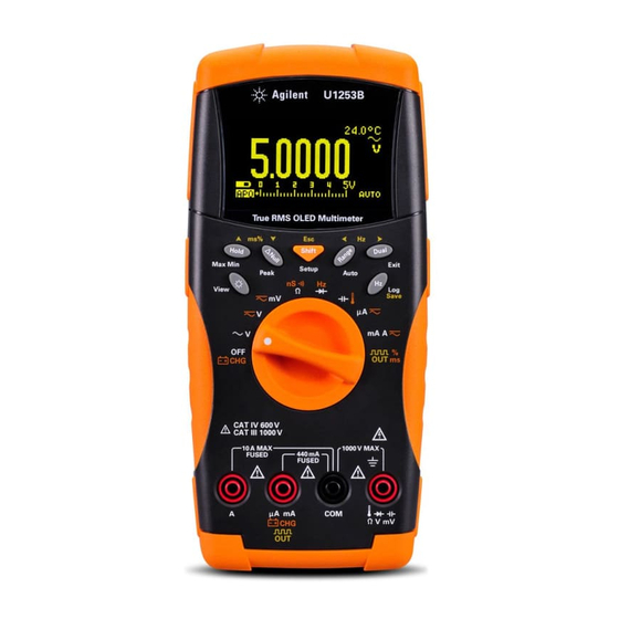
Getting Started Introducing the Agilent U1253B True RMS OLED Multimeter The key features of the true RMS OLED multimeter are: • DC, AC and AC+DC voltage and current measurements. • True RMS measurement for both AC voltage and current. • Rechargeable Ni- MH battery with built- in charging capability. - Page 25 Getting Started • Agilent GUI Application Software (IR- USB cable sold separately). • Closed case calibration. • 50,000- count precision true RMS digital multimeter, designed to meet EN/IEC 61010- 1:2001 Category III 1000 V/ Category IV 600 V, Pollution Degree 2 standards. U1253B User’s and Service Guide...
-
Page 26: Check The Shipment
Getting Started Check the shipment Verify that you have received the following items with your multimeter: • 4 mm probes • Test leads • Alligator clips • Rechargeable 7.2 V battery • Power cord & AC adapter • Quick Start Guide •... -
Page 27: Adjusting The Tilt-Stand
Getting Started Adjusting the tilt-stand To adjust the multimeter to a 60° standing position, pull the tilt- stand outward to its maximum reach. IR-USB cable To PC (host) ° Tilt-stand at 60 Figure 1-1 Tilt-stand at 60° U1253B User’s and Service Guide... - Page 28 Getting Started To adjust the multimeter to a 30° standing position, bend the tip of the stand so that it is parallel to ground, then pull the stand outward to its maximum reach. IR-USB cable To PC (host) ° Tilt-stand at 30 Figure 1-2 Tilt-stand at 30°...
-
Page 29: Figure 1-3 Tilt-Stand At Hanging Position
Getting Started Detach the tilt-stand Extend the tilt-stand until its maximum reach Re-attach the tilt-stand to an upright position Flip the tilt-stand over until this side of the stand is facing the multimeter as opposed to facing you Figure 1-3 Tilt-stand at hanging position U1253B User’s and Service Guide... -
Page 30: The Front Panel At A Glance
Getting Started The front panel at a glance Display Keypad Rotary switch Terminal connectors Figure 1-4 U1253B front panel U1253B User’s and Service Guide... -
Page 31: The Rear Panel At A Glance
Getting Started The rear panel at a glance IR communication port Test probe holders Tilt-stand Battery access cover Figure 1-5 Rear panel U1253B User’s and Service Guide... -
Page 32: The Rotary Switch At A Glance
Getting Started The rotary switch at a glance Figure 1-6 Rotary switch Table 1-1 Rotary switch description and functions Description/Function Charge mode or OFF AC V DC V, AC V, or AC + DC V DC mV, AC mV, or AC + DC mV Resistance (Ω), continuity, or conductance (nS) Frequency counter or diode Capacitance or temperature... -
Page 33: The Keypad At A Glance
Getting Started The keypad at a glance The operation of each key is explained in Table 1- 2 below. Pressing a key displays a related symbol and emits a sound on the beeper. Turning the rotary switch to another position resets the current operation of the key. -
Page 34: Table 1-2 Keypad Descriptions And Functions
Getting Started Table 1-2 Keypad descriptions and functions Button Function when pressed for less than 1 second Function when pressed for more than 1 second cycles through OLED display brightness • enters Log Review mode. Press to switch levels. between manual or interval logging data. •... - Page 35 Getting Started Table 1-2 Keypad descriptions and functions (continued) Button Function when pressed for less than 1 second Function when pressed for more than 1 second scrolls through the available exits Hold, Null, Dynamic Recording, 1 ms Peak dual-combination displays (except when the Hold, and dual display modes.
-
Page 36: The Display At A Glance
Getting Started The display at a glance The display symbols are explained in the following tables. Table 1-3 General display symbols OLED Annunciator Description Remote control Type of thermocouple: (K-type); (J-type) Null math function Relative value for Null mode Diode Audible continuity: (SINGLE) or (TONE) depending on Setup configuration... -
Page 37: Table 1-4 Primary Display Symbols
Getting Started Table 1-3 General display symbols (continued) OLED Annunciator Description Trigger (manual) Hold Dynamic Recording mode: Present value on primary display Dynamic Recording mode: Maximum value on primary display Dynamic Recording mode: Minimum value on primary display Dynamic Recording mode: Average value on primary display 1 ms Peak Hold mode: Positive peak value on primary display 1 ms Peak Hold mode: Negative peak value on primary display Hazardous voltage annunciator for measuring voltage ≥... - Page 38 Getting Started Table 1-4 Primary display symbols (continued) OLED Annunciator Description Decibel unit relative to 1 mW Decibel unit relative to 1 V Frequency units: Hz, kHz, MHz Resistance units: Ω, kΩ, MΩ Conductance unit: nS Voltage units: mV, V Current units: μA, mA, A Capacitance units: nF, μF, mF Celsius temperature unit...
-
Page 39: Table 1-5 Secondary Display Symbols
Getting Started Table 1-4 Primary display symbols (continued) OLED Annunciator Description Reference impedance for the dBm unit Scale of bar graph The secondary display annunciators are described below. Table 1-5 Secondary display symbols OLED Annunciator Description AC+DC Polarity, digits, and decimal points for secondary display Decibel unit relative to 1 mW Decibel unit relative to 1 V Frequency units: Hz, kHz, MHz... - Page 40 Getting Started Table 1-5 Secondary display symbols (continued) OLED Annunciator Description Celsius ambient temperature unit Fahrenheit ambient temperature unit No ambient temperature compensation; just thermocouple measurement Pulse width unit Bias display Leak display Elapsed time unit: s (second) for Dynamic Recording and 1 ms Peak Hold modes Hazardous voltage annunciator for measuring voltage >= 30 V or Overload The analog bar emulates the needle on an analog multimeter, without displaying the overshoot.
-
Page 41: Table 1-6 Analog Bar Range And Counts
Getting Started The “+” or “–” sign indicates whether the measured or calculated value is positive or negative. Each segment represents 2000 or 400 counts depending on the range indicated on the peak bar graph. See the following table. Table 1-6 Analog bar range and counts Range Counts/segments Used for the function... -
Page 42: Selecting Display With The Shift Button
Getting Started Selecting display with the Shift button The table below shows the primary display selection, with respect to measurement function (rotary switch position), using the Shift button. Table 1-7 Selecting display with the Shift button Rotary switch position (Function) Primary display AC V (AC voltage) -
Page 43: Selecting Display With The Dual Button
Getting Started Table 1-7 Selecting display with the Shift button (continued) Rotary switch position (Function) Primary display DC mA AC mA (AC+DC current) (With the positive probe inserted into the μA.mA AC+DC mA terminal) % (0 mA to 20 mA or 4 mA to 20 mA (Reading in mA or A is shown as secondary display) DC A (AC+DC current) - Page 44 Getting Started Table 1-8 Selecting display with the Dual button (continued) Rotary switch position (Function) Primary display Secondary display DC V Hz (DC coupling) dBm or dBV DC V (Default is DC voltage) DC V AC V AC V Hz (AC coupling) dBm or dBV AC V (Press...
- Page 45 Getting Started Table 1-8 Selecting display with the Dual button (continued) Rotary switch position (Function) Primary display Secondary display AC+DC μA Hz (AC coupling) AC+DC μA AC μA (Press twice to select AC+DC AC+DC μA DC μA current) DC mA Hz (DC coupling) DC mA AC mA...
- Page 46 Getting Started Table 1-8 Selecting display with the Dual button (continued) Rotary switch position (Function) Primary display Secondary display If ºC/ºF or ºF/ºC dual-display is selected in the Setup, then the secondary display will indicate the temperature in the other unit (as opposed to the primary display).
-
Page 47: Selecting Display With The Hz Button
Getting Started Selecting display with the Hz button The frequency measurement function is able to detect the presence of harmonic currents in neutral conductors and determine whether these neutral currents are the result of unbalanced phases or non- linear loads. •... - Page 48 Getting Started Table 1-9 Selecting display with the Hz button (continued) Rotary switch position (Function) Primary display Secondary display Frequency (Hz) Pulse width (ms) AC mV (Press to select AC voltage) Duty cycle (%) Frequency (Hz) Pulse width (ms) AC+DC mV (Press twice to select AC+DC voltage) Duty cycle (%)
-
Page 49: The Terminals At A Glance
Getting Started Table 1-9 Selecting display with the Hz button (continued) Rotary switch position (Function) Primary display Secondary display Frequency (Hz) Pulse width (ms) Hz (Frequency counter) Pulse width (ms) Frequency (Hz) (Only applicable for Divide-1 input) Duty cycle (%) The terminals at a glance To avoid damaging the multimeter, do not exceed the rated input limit. -
Page 50: Table 1-10 Terminal Connections For Different Measurement
Getting Started Table 1-10 Terminal connections for different measurement functions Rotary switch position Input terminals Overload protection 1000 Vrms 1000 Vrms for short circuit <0.3 A 440 mA/1000 V, 30 kA μA.mA fast-acting fuse 11 A/1000 V, 30kA fast-acting fuse 440 mA/1000 V fast-acting fuse U1253B User’s and Service Guide... -
Page 51: Making Measurements
Measuring Resistance, Conductance, and Testing Continuity Testing Diodes Measuring Capacitance Measuring Temperature Alerts and Warning During Measurement Overload alert Input warning Charge terminal alert This chapter contains information on how to make measurements using the U1253B true RMS OLED multimeter. Agilent Technologies... -
Page 52: Understanding The Measurement Instructions
Making Measurements Understanding The Measurement Instructions When making measurements, follow the numerical steps labelled in the diagrams. Refer to Table 2- 1 below for a description of the steps. Table 2-1 Numerical steps descriptions Instructions Turn the rotary switch to the measurement option shown in the diagram Connect the test leads into the input terminals shown in the diagram Probe the test points Read the results on the display... -
Page 53: Measuring Ac Voltage
Making Measurements Measuring AC voltage Set up your multimeter to measure AC voltage as shown in Figure 2- 1. Probe the test points and read the display. Red Lead Black Lead Figure 2-1 Measuring AC voltage • Press if necessary to ensure is shown on the display. -
Page 54: Measuring Dc Voltage
Making Measurements Measuring DC voltage Set up your multimeter to measure DC voltage as shown in Figure 2- 2. Probe the test points and read the display. • Press if necessary to ensure that is shown on the display. N O T E •... -
Page 55: Measuring Current
Making Measurements Measuring Current µA and mA measurement Set up your multimeter to measure µA and mA as shown in Figure 2- 3. Probe the test and read the display. • Press if necessary to ensure is shown on the display. N O T E •... -
Page 56: Figure 2-3 Measuring Μa And Ma Current
Making Measurements Black Lead Red Lead Figure 2-3 Measuring μA and mA current U1253B User’s and Service Guide... -
Page 57: Percentage Scale Of 4 Ma To 20 Ma
Making Measurements Percentage scale of 4 mA to 20 mA Set up the multimeter to measure percentage scale as shown Figure 2- 4. Probe the test points and read the display. • Press to select percentage scale display. N O T E Ensure that is shown on the display. -
Page 58: Figure 2-4 Measurement Scale Of 4 Ma To 20 Ma
Making Measurements Black Lead Red Lead Figure 2-4 Measurement scale of 4 mA to 20 mA U1253B User’s and Service Guide... -
Page 59: A (Ampere) Measurement
Making Measurements A (ampere) measurement Set up the multimeter to measure A (ampere) as shown in Figure 2- 5. Probe the test points and read the display. Connect the red and black test leads to 10 A input terminals N O T E A (red) and COM (black) respectively. -
Page 60: Frequency Counter
Making Measurements Frequency Counter • Use the frequency counter only for low voltage applications. WA R N I N G Never use the frequency counter on an AC power line system. • For input more than 30 Vpp, you are required to use frequency measurement mode available under the current or voltage measurement instead of frequency counter. -
Page 61: Figure 2-6 Measuring Frequency
Making Measurements Press Range Red Lead Black Lead Figure 2-6 Measuring frequency U1253B User’s and Service Guide... -
Page 62: Measuring Resistance, Conductance, And Testing Continuity
Making Measurements Measuring Resistance, Conductance, and Testing Continuity Disconnect circuit power and discharge all high-voltage capacitors C A U T I O N before measuring resistance or conductance, or testing circuit continuity, to avoid damaging the multimeter or the device under test. Set up the multimeter to measure resistance as shown in Figure 2- 8. -
Page 63: Figure 2-7 Type Of Display When Smart
Making Measurements The Smart Ω is applicable for 500 Ω, 5 kΩ, 50 kΩ, and 500 kΩ resistance range only. The maximum correctable offset/bias voltage is ±1.9 V for 500 Ω range and ±0.35 V for 5 kΩ, 50 kΩ, and 500 kΩ range. to enable Smart Ω... -
Page 64: Figure 2-8 Measuring Resistance
Making Measurements Red Lead Black Lead Figure 2-8 Measuring resistance U1253B User’s and Service Guide... -
Page 65: Figure 2-9 Resistance, Audible Continuity, And Conductance
Making Measurements Resistance Press Shift Audible continuity Press Shift Press Shift Conductance Figure 2-9 Resistance, audible continuity, and conductance tests U1253B User’s and Service Guide... -
Page 66: Table 2-3 Audible Continuity Measurement Range
Making Measurements Audible continuity In the range of 500 Ω range, the beeper will emit a sound if the resistance value falls below 10 Ω. For other ranges, the beeper will emit a sound if the resistance falls below the typical values listed in Table 2- 3 below. -
Page 67: Figure 2-10 Short Continuity And Open Continuity Test
Making Measurements Short continuity Press Press Open continuity Figure 2-10 Short continuity and open continuity test Conductance Set up the multimeter to measure conductance as shown in Figure 2- 11. Probe the test points and read the display. The conductance measurement function makes it easier to measure very high resistance of up to 100 GΩ. -
Page 68: Figure 2-11 Conductance Measurement
Making Measurements Red Lead Black Lead Figure 2-11 Conductance measurement U1253B User’s and Service Guide... -
Page 69: Testing Diodes
Making Measurements Testing Diodes Disconnect circuit power and discharge all high-voltage capacitors C A U T I O N before testing diodes to avoid damaging the multimeter. To test a diode, turn the power off to the circuit and remove the diode from the circuit. -
Page 70: Figure 2-12 Measuring The Forward Bias Of A Diode
Making Measurements Red Lead Black Lead Figure 2-12 Measuring the forward bias of a diode U1253B User’s and Service Guide... -
Page 71: Figure 2-13 Measuring The Reverse Bias Of A Diode
Making Measurements Red Lead Black Lead Figure 2-13 Measuring the reverse bias of a diode U1253B User’s and Service Guide... -
Page 72: Measuring Capacitance
Making Measurements Measuring Capacitance Disconnect circuit power and discharge all high-voltage capacitors C A U T I O N before measuring capacitance to avoid damaging the multimeter or the device under test. Use the DC voltage function in order to confirm that a capacitor has fully discharged. -
Page 73: Figure 2-14 Capacitance Measurements
Making Measurements Red Lead Black Lead Figure 2-14 Capacitance measurements U1253B User’s and Service Guide... -
Page 74: Measuring Temperature
Making Measurements Measuring Temperature Do not bend the thermocouple leads at sharp angles. Repeated C A U T I O N bending over a period of time can result in the leads breaking. The bead- type thermocouple probe is suitable for measuring temperatures from –20 °C to 200 °C in PTFE- compatible environments. -
Page 75: Figure 2-15 Connecting The Thermal Probe Into The Non-Compensation Transfer Adapter
Making Measurements Figure 2-15 Connecting the thermal probe into the non-compensation transfer adapter Figure 2-16 Connecting the probe with adapter into the multimeter U1253B User’s and Service Guide... - Page 76 Making Measurements If you are working in a constantly varying environment, where ambient temperatures are not constant, do the following: 1 Press to select 0 °C compensation. This allows a quick measurement of the relative temperature. 2 Avoid contact between the thermocouple probe and the surface to be measured.
-
Page 77: Figure 2-17 Surface Temperature Measurement
Making Measurements Press Dual Figure 2-17 Surface temperature measurement U1253B User’s and Service Guide... -
Page 78: Alerts And Warning During Measurement
Making Measurements Alerts and Warning During Measurement Overload alert For your own safety, look out for this alert. When you see this alert, WA R N I N G immediately remove the test leads from the measuring source. This multimeter provides an overload alert for voltage measurement in both auto and manual range modes. -
Page 79: Input Warning
Making Measurements Input warning The multimeter emits a continuous beep when the test lead is inserted to the A input terminal but the rotary switch is not set to the corresponding mA.A position. A warning message Error ON A INPUT will be displayed until the test lead is removed from the A input terminal. -
Page 80: Charge Terminal Alert
Making Measurements Charge terminal alert The multimeter emits a continuous beep when the terminal detects a voltage level of more than 5 V and the rotary switch is not set to the corresponding position. A warning message Error ON mA INPUT will be displayed until the lead is removed from the input terminal. -
Page 81: Dynamic Recording
Null (Relative) Decibel Display 1 ms Peak Hold Data Logging Manual logging Interval logging Reviewing logged data Square Wave Output Remote Communication This chapter contains information on the functions and features available for the U1253B true RMS OLED multimeter. Agilent Technologies... -
Page 82: Functions And Features
Functions and Features Dynamic Recording The Dynamic Recording mode can be used to detect intermittent turn- on or turn- off voltage, current surges or to verify measurement performance without you being present during the process. While the readings are being recorded, you are free to perform other tasks. -
Page 83: Figure 3-1 Dynamic Recording Mode Operation
Functions and Features Press Max Min for > 1 sec. Press Max Min Press Max Min for > 1 sec. Or Press for > 1 sec. Press Max Min Press Max Min for > 1 sec. Or Press for > 1 sec. Press Max Min Press Max Min for >... -
Page 84: Data Hold (Trigger Hold)
Functions and Features Data Hold (Trigger Hold) The Data Hold function allows you to freeze the displayed value. 1 Press to freeze the displayed value and to enter manual trigger mode. is displayed. 2 Press again to freeze the next value being measured. -
Page 85: Figure 3-2 Data Hold Mode Operation
Functions and Features Press Hold Press Shift Press Press Reading Reading Hold Hold (“T” flashes) (“T” flashes) Updated Updated Figure 3-2 Data hold mode operation U1253B User’s and Service Guide... -
Page 86: Refresh Hold
Functions and Features Refresh Hold The Refresh Hold function allows you to freeze the displayed value. The bar- graph is not held and will continue to reflect the instantaneous measured value. You can use the Setup mode to enable Refresh Hold mode when you are working with fluctuating values. -
Page 87: Figure 3-3 Refresh Hold Mode Operation
Functions and Features Press Hold Press Shift Variation count Reading > setting Updated (“R” flashes) Figure 3-3 Refresh hold mode operation • For voltage and current measurements, the held value will not be N O T E updated if the reading is below 500 counts. •... -
Page 88: Null (Relative)
Functions and Features Null (Relative) The Null function subtracts a stored value from the present measurement and displays the difference between the two. 1 Press to store the displayed reading as the reference value to be subtracted from subsequent measurements and to set the display to zero. displayed. -
Page 89: Figure 3-4 Null (Relative) Mode Operation
Functions and Features Press Null Press Null while O’BASE is being displayed to exit this mode Auto-return Press after 3 seconds Null Figure 3-4 Null (relative) mode operation U1253B User’s and Service Guide... -
Page 90: Decibel Display
Functions and Features Decibel Display The dBm unit calculates the power delivered to a reference resistance relative to 1 mW and can be applied to DC V, AC V and AC+DC V measurements for decibel conversion. Voltage measurement is converted to dBm using the following formula: ⎛... -
Page 91: Figure 3-5 Dbm Display Mode Operation
Functions and Features Press Dual Press Dual for > 1 sec. Press Press Dual Dual Figure 3-5 dBm display mode operation U1253B User’s and Service Guide... -
Page 92: Figure 3-6 Dbv Display Mode Operation
Functions and Features Press Dual Press Dual for > 1 sec. Press Press Dual Dual Figure 3-6 dBV display mode operation U1253B User’s and Service Guide... -
Page 93: Ms Peak Hold
Functions and Features 1 ms Peak Hold The Peak Hold function allows the measurement of peak voltage for analysis of components such as power distribution transformers and power factor correction capacitors. The peak voltage obtained can be used to determine the crest factor: Peak value ------------------------------------------------ Crest factor... -
Page 94: Figure 3-7 1 Ms Peak Hold Mode Operation
Functions and Features Press Peak for > 1 sec. Press Max Min Press Dual Start to capture Start to capture to reset Press Max Min Press Press Range Hold (Note: pressing Hold when in Negative P-HOLD– will change the display into Positive P-HOLD+.) Figure 3-7 1 ms peak hold mode operation U1253B User’s and Service Guide... -
Page 95: Data Logging
Functions and Features Data Logging The data logging function provides the convenience of recording test data for future review or analysis. Since data is stored in nonvolatile memory, the data remains saved when the multimeter is turned OFF or the battery is changed. -
Page 96: Figure 3-8 Manual (Hand) Logging Mode Operation
Functions and Features Press Log for > 1 sec. Press Log for > 1 sec. again to log each data Display returns to normal automatically after 3 seconds Figure 3-8 Manual (hand) logging mode operation The maximum number of readings that can be stored is 100 entries. When N O T E the 100 entries are all occupied, the logging index will indicate “Full”, as shown in... -
Page 97: Interval Logging
Functions and Features Interval logging Firstly ensure that interval (time) logging is specified in Setup mode. 1 Press for more than 1 second to store the present value and function on the primary display into the non- volatile memory. The and the logging index will be indicated. -
Page 98: Figure 3-10 Interval (Time) Logging Mode Operation
Functions and Features Press Log for > 1 sec. After first interval Press Log for > 1 sec. Press Log for > 1 sec. Stop logging After last interval Last interval Figure 3-10 Interval (time) logging mode operation U1253B User’s and Service Guide... -
Page 99: Reviewing Logged Data
Functions and Features Reviewing logged data 1 Press for more than 1 second to enter Log Review mode. The last logged entry, , and the last logging index are displayed. 2 Press to switch between manual (hand) and interval (time) logging review mode. 3 Press to ascend or to descend through the logged... -
Page 100: Figure 3-11 Log Review Mode Operation
Functions and Features Press View for > 1 sec. Press View Press Press Press Press Press Press Press Press Press Press Press Press Press Press Press Log for > 1 sec. Press Log for > 1 sec. to clear all manual logs to clear all interval logs Figure 3-11 Log review mode operation U1253B User’s and Service Guide... -
Page 101: Square Wave Output
Functions and Features Square Wave Output The U1253B true RMS OLED multimeter’s square wave output can be used to generate a PWM (pulse width modulation) output or provide a synchronous clock source (baud rate generator). You can also use this function to check and calibrate flow- meter displays, counters, tachometers, oscilloscopes, frequency converters, frequency transmitters, and other frequency input devices. -
Page 102: Figure 3-12 Frequency Adjustment For Square Wave Output
Functions and Features Press Press Press Press Figure 3-12 Frequency adjustment for square wave output U1253B User’s and Service Guide... -
Page 103: Figure 3-13 Duty Cycle Adjustment For Square Wave Output
Functions and Features Selecting square wave output duty cycle 1 Set the rotary switch to 2 Press to select duty cycle (%) on the primary display. 3 Press to adjust the duty cycle. The duty cycle can be stepped through 256 steps, with each step equivalent to 0.390625%. -
Page 104: Figure 3-14 Pulse Width Adjustment For Square Wave Output
Functions and Features Selecting square wave output pulse width 1 Set the rotary switch to 2 Press to select pulse width (ms) on the primary display. 3 Press to adjust the pulse width. The pulse width can be stepped through 256 steps, with each step equivalent to 1/(256 ×... -
Page 105: Remote Communication
Functions and Features Remote Communication This multimeter has a bidirectional (full duplex) communication capability that enables data transfer from the multimeter to a PC. The required accessory for this is an optional IR- USB cable, to be used with an application software that is downloadable from the Agilent Web site. - Page 106 Functions and Features U1253B User’s and Service Guide...
-
Page 107: Selecting Setup Mode
Smooth refresh rate Returning to default factory settings Setting the battery type Setting the DC filter This chapter will show you how to change the default factory settings of the U1253B true RMS OLED multimeter and other available setting options. Agilent Technologies... -
Page 108: Changing The Default Settings
Changing the Default Settings Selecting Setup Mode To enter Setup mode, press and hold for more than 1 second. To change a menu item setting in Setup mode, perform the following steps: 1 Press to view the selected menu pages. 2 Press to navigate to the item that needs to be changed. -
Page 109: Default Factory Settings And Available Setting Options
Changing the Default Settings Default Factory Settings and Available Setting Options The following table shows the various menu items with their respective default settings and available options. Table 4-1 Default factory settings and available setting options for each feature Default factory Menu Feature setting... - Page 110 Changing the Default Settings Table 4-1 Default factory settings and available setting options for each feature Default factory Menu Feature setting Available setting options T-TYPE Thermocouple type. • Available options: K-type or J-type T-UNIT °C Temperature unit. • Available options: •...
- Page 111 Changing the Default Settings Table 4-1 Default factory settings and available setting options for each feature Default factory Menu Feature setting Available setting options BAUD 9600 Baud rate for remote communication with a PC (remote control). Available options: 2400, 4800, 9600, and 19200. DATA BIT Data bit length for remote communication with a PC.
- Page 112 Changing the Default Settings Press Press Press Press Press Press Press Press Press Press Press Press Press Press Press Press Press Press Press Press Figure 4-1 Setup menu screens U1253B User’s and Service Guide...
-
Page 113: Setting Data Hold/Refresh Hold Mode
Changing the Default Settings Setting Data Hold/Refresh Hold mode 1 Set menu item RHOLD to “OFF” to enable Data Hold mode (manual trigger by key or bus via remote control). 2 Set menu item RHOLD within the range of 100 to 9900 to enable Refresh Hold mode (automatic trigger). -
Page 114: Setting Data Logging Mode
Changing the Default Settings Setting data logging mode 1 Set to “HAND” to enable manual (hand) data logging, or set to “TIME” to enable interval (time) data logging. Refer Figure 4- 3 below. Press Hz to edit Press to switch between HAND (data logging) and TIME (interval logging) Press Hz to save... -
Page 115: Figure 4-4 Log Time Setup For Interval (Time) Logging
Changing the Default Settings Press Hz to edit Press to edit the value Press to go to the digit you want to edit Press Hz to save and exit or press Esc to exit without saving Figure 4-4 Log time setup for interval (time) logging U1253B User’s and Service Guide... -
Page 116: Setting Db Measurement
Changing the Default Settings Setting dB measurement The decibel unit can be disabled by setting this to “OFF”. The available options are dBm, dBV, and OFF. For dBm measurement, the reference impedance can be set by the “dBm- R” menu item. Press Hz to edit Press... -
Page 117: Setting Reference Impedance For Dbm Measurement
Changing the Default Settings Setting reference impedance for dBm measurement The reference impedance for dBm measurement can be set to any value within the range of 1 to 9999 Ω. The default value is 50 Ω. Press Hz to edit Press to edit the value Press... -
Page 118: Setting Thermocouple Types
Changing the Default Settings Setting thermocouple types The types of thermocouple sensor that can be selected are J- type and K- type. The default type is K- type. Press to switch between K-type and J-type Press Hz to save and exit or press Esc to exit without saving Figure 4-7 Thermocouple type setup... -
Page 119: Figure 4-8 Temperature Unit Setup
Changing the Default Settings The temperature unit setting at power on is locked by default and thus N O T E temperature unit editing is not allowed unless it is unlocked. Press and hold for more than 1 second to unlock the temperature unit setting and the lock sign will be removed. -
Page 120: Setting Percentage Scale Readout
Changing the Default Settings Setting percentage scale readout This setting converts the DC current measurement display to percentage scale readout: 0% to 100% based on a range of 4 mA to 20 mA or 0 mA to 20 mA. For example, a 25% readout represents a DC current of 8 mA for the 4 mA to 20 mA range, or a DC current of 5 mA for the 0 mA to 20 mA range. -
Page 121: Sound Setting For Continuity Test
Changing the Default Settings Sound setting for continuity test This setting determines the sound used in the continuity test. Select "SINGLE" for a single- frequency beep, select “OFF” for a silent beep, or select "TONE" for a continuous string of beeps with varying frequencies. Press Hz to edit Press... -
Page 122: Setting Minimum Measurable Frequency
Changing the Default Settings Setting minimum measurable frequency The setup for minimum measurable frequency will influence the measurement rates for frequency, duty cycle, and pulse width. The typical measurement rate as defined in the specification is based on a minimum measurable frequency of 1 Hz. -
Page 123: Setting Beep Frequency
Changing the Default Settings Setting beep frequency The beep frequency can be set to 4800 Hz, 2400 Hz, 1200 Hz, or 600 Hz. “OFF” disables the beep. Press Hz to edit Press to choose the value Press to choose the value Press to choose the value Press... -
Page 124: Setting Auto Power Off Mode
Changing the Default Settings Setting Auto Power Off mode • To enable Auto Power Off (APO) set the timer to any value within the range of 1 to 99 minutes. • The multimeter may turn off automatically (with APO enabled) if neither of the following happens within that time period: •... -
Page 125: Figure 4-13 Automatic Power Saving Setup
Changing the Default Settings Press Hz to edit Press to edit the value Set all digits to ZERO to set APO to “OFF” Press to go to the digit you want to edit Press Hz to save and exit or press Esc to exit without saving Figure 4-13 Automatic power saving setup U1253B User’s and Service Guide... -
Page 126: Setting Power-On Backlight Brightness Level
Changing the Default Settings Setting power-on backlight brightness level The brightness level that is displayed when the multimeter turns on can be set to HIGH, MEDIUM, or LOW. Press Hz to edit Press to configure Press to configure Press Hz to save and exit or press Esc to exit without saving... -
Page 127: Setting The Power-On Melody
Changing the Default Settings Setting the power-on melody The melody that is played when the multimeter turns on can be set to FACTORY or OFF. Press Hz to edit Press to toggle between FACTORY or OFF and exit to exit without saving Press Hz to save or press ESC Figure 4-15 Power-on melody setup... -
Page 128: Setting Baud Rate
Changing the Default Settings Setting baud rate The baud rate used in the remote communication with a PC can be set as 2400, 4800, 9600, or 19200 bits/second. Press Hz to edit Press to choose the value Press to choose the value Press to choose the value Press Hz to save... -
Page 129: Setting Data Bits
Changing the Default Settings Setting data bits The number of data bits (data width) for remote communication with a PC can be set to either 8 or 7 bits. The number of stop bit is always 1, and this cannot be changed. -
Page 130: Setting Parity Check
Changing the Default Settings Setting parity check The parity check for remote communication with a PC can be set to either NONE, ODD, or EVEN. Press Hz to edit Press to configure Press to configure Press Hz to save and exit or press Esc to exit without saving Figure 4-19 Parity check setup for remote control U1253B User’s and Service Guide... -
Page 131: Setting Echo Mode
Changing the Default Settings Setting echo mode • Turning echo mode to “ON” enables the transmitted characters to be echoed on the PC in remote communication. • This is useful when developing PC programs which use SCPI commands. It is recommended that you disable this function during normal operation. -
Page 132: Setting Print Mode
Changing the Default Settings Setting print mode Turning print mode “ON” enables the printing of measured data to a PC that is connected to the multimeter via the remote interface when a measurement cycle is completed. In this mode, the multimeter continuously sends the latest data to the host, but does not accept any commands from the host. -
Page 133: Revision
Changing the Default Settings Revision The revision number of the firmware will be indicated. Figure 4-22 Revision number Serial number The last 8 digits of the serial number will be indicated. Figure 4-23 Serial number U1253B User’s and Service Guide... -
Page 134: Voltage Alert
Changing the Default Settings Voltage alert To enable an alert tone for overvoltage, select an overvoltage value within the range of 1 V to 1010 V. To disable this function, set all digits to 0 (“OFF”). Press Hz to edit Press to edit the value Press... -
Page 135: M-Initial
Changing the Default Settings M-initial You may select the initial measurement functions as FACTORY or USER. The initial measurement functions and range can be set according to Table 4- 2 below. Table 4-2 Available settings for M-initial Function position Function setting Range setting AC V Auto or manual ranges... -
Page 136: Figure 4-25 Setting Initial Measurement Functions
Changing the Default Settings For another example, when you turn the rotary switch to position, the initial measurement range is Auto according to default factory setting. In order to choose a different range, you will have to press the button. If you prefer to have a different set of initial measurement functions, change the M- INITIAL setting to USER, and press button. -
Page 137: Figure 4-27 Editing Initial Measurement Function/Range
Changing the Default Settings Press Press Press to choose item to choose item Figure 4-26 Navigating between the initial functions pages Then press to enter the EDIT mode. In the EDIT mode, Press to change the initial (default) measurement range of a selected function. For example, Figure 4- 27 below shows the initial range of the... -
Page 138: Figure 4-28 Editing Initial Measurement Function/Range And Initial Output Values
Changing the Default Settings • The F7 default measurement range for DC μA is changed from Auto to 5000 μA; • The F8 default measurement range for DC mA is changed from Auto to 50 mA; • The F8A default measurement range for DC A is changed from Auto to 5 A;... -
Page 139: Smooth Refresh Rate
Changing the Default Settings Smooth refresh rate The SMOOTH mode (FAST, NORMAL or SLOW options) is used to smoothen the refresh rate of the readings, in order to reduce the impact of unexpected noise and helps to get a stable reading. It applies to all measurement functions except capacitance and frequency counter (including duty cycle and pulse width measurements). -
Page 140: Returning To Default Factory Settings
Changing the Default Settings Returning to default factory settings • Set to “YES”, then press for more than 1 second to reset to default factory settings (all except the temperature setting). • The Reset menu item automatically reverts to menu page 1 after a reset has taken place. -
Page 141: Setting The Battery Type
Changing the Default Settings Setting the battery type The battery type for the multimeter can be set to either 7.2 V or 8.4 V. Press Hz to edit Press to switch between 7.2 V and 8.4 V Press Hz to save and exit or press Esc to exit without saving... -
Page 142: Setting The Dc Filter
Changing the Default Settings Setting the DC filter This setting is used to filter AC signal in DC measuring path. The DC filter is set to “OFF” by default. To enable this function, set this to “ON”. Press Hz to edit Press to switch between OFF and ON... -
Page 143: Maintenance
Maintenance Introduction General maintenance Battery replacement Storage considerations Charging the battery Fuse checking procedure Fuse replacement Troubleshooting Replaceable Parts To order replaceable parts This chapter will help you to troubleshoot if the U1253B true RMS OLED multimeter malfunctions. Agilent Technologies... -
Page 144: Introduction
Maintenance Introduction Any repair or service which is not covered in this manual should only C A U T I O N be performed by qualified personnel. General maintenance Ensure that terminal connections are correct for a particular WA R N I N G measurement before making the measurement. -
Page 145: Battery Replacement
Maintenance Battery replacement This multimeter is powered by a 9 V Ni- MH rechargeable battery (7.2 nominal voltage) or 9 V Ni- MH rechargeable battery (8.4 V nominal voltage). Use only the specified type (refer to Figure 5- 1 below). Alternatively you may also use a 9 V Alkaline battery (ANSI/NEDA 1604A or IEC 6LR61) or a 9 V Carbon- zinc battery (ANSI/NEDA 1604D or IEC6F22) to power the U1253B. -
Page 146: Figure 5-2 Rear Panel Of The Agilent U1253B True Rms Oled
Maintenance 1 On the rear panel, turn the screw on the battery cover counterclockwise from the LOCK position to OPEN. Figure 5-2 Rear panel of the Agilent U1253B True RMS OLED Multimeter 2 Slide the battery cover down. 3 Lift the battery cover up. 4 Replace with the specified battery. -
Page 147: Storage Considerations
Maintenance List of compatible batteries for the Agilent U1253B : N O T E • 9 V Alkaline non-chargeable battery (ANSI/NEDA 1604A or IEC 6LR61) • 9 V Carbon-zinc non-chargeable battery (ANSI/NEDA 1604D or IEC6F22) • 9 V size 300mAH Ni-MH rechargeable battery, 7.2 V nominal voltage •... -
Page 148: Charging The Battery
Maintenance Charging the battery Do not discharge the battery by shorting it or subjecting it to reverse WA R N I N G polarity. Make sure a battery is rechargeable before charging it. Do not rotate the rotary switch when the battery is being charged. C A U T I O N •... - Page 149 Maintenance It is strongly recommended that you use the specified 24- volt DC adapter included as an accessory to charge the rechargeable battery. Never rotate the rotary switch while the battery is being charged because a DC voltage of 24 V is applied to the charging terminals.
-
Page 150: Figure 5-3 Self-Testing Time Display
Maintenance Figure 5-3 Self-testing time display Table 5-1 Battery voltage and corresponding percentage of charges in standby and charging modes Condition Battery voltage Proportional percentage Trickle 6.0 V to 8.2 V 0% to 100% Charging 7.2 V to 10.0 V 0% to 100% 6 After pressing or in the case of a restart, the... -
Page 151: Figure 5-4 Performing Self-Test
Maintenance Figure 5-4 Performing self-test Table 5-2 Error messages Error Error message OVER LIMIT 1 No battery inside 2 Faulty battery 3 Battery is fully charged CHARGE ERROR 1 If charging battery more than 12 V or less than 5 V 2 In 3 minutes, if the battery voltage does not go upwards then charge error U1253B User’s and Service Guide... -
Page 152: Figure 5-5 Charging Mode
Maintenance • If the OVER LIMIT message is displayed, and there is a battery inside N O T E the multimeter, please do not charge the battery. • If the CHARGE ERROR message is displayed, check whether the battery is the specified type. For the correct battery type, refer to “List of compatible batteries for the Agilent U1253B :”... -
Page 153: Figure 5-6 Fully Charged And In The Trickle State
Maintenance Figure 5-6 Fully charged and in the trickle state 8 Once the charging is completed, the FULLY CHARGED message will be displayed. A trickle charging current will be drawn to maintain the battery capacity. 9 Remove the DC adapter when the battery has been fully charged. -
Page 154: Figure 5-7 Battery Charging Procedures
Maintenance Press Shift or after time up to start charging Over limit level ERROR Charge error Battery can be charged Fully charged or time out Figure 5-7 Battery charging procedures U1253B User’s and Service Guide... -
Page 155: Fuse Checking Procedure
Maintenance Fuse checking procedure It is recommended that you check the fuses of the multimeter before using it. Follow the instructions below to test the fuses inside the multimeter. Refer to Figure 5- 9 the respective positions of Fuse 1 and Fuse 2. 1 Set the rotary switch to 2 Connect the red test lead to the input terminal Figure 5-8 Fuse checking procedures... -
Page 156: Table 5-3 U1253B Measurement Readings For Fuse Checking
Maintenance 3 To test Fuse 1, place the tip of the test probe on the right half of input terminal . Ensure that the probe tip touches the metal inside the input terminal, as shown in Figure 5- 4 To test Fuse 2, place and touch the tip of the test probe on the right half of input terminal . -
Page 157: Fuse Replacement
Maintenance Fuse replacement This manual provides only the fuse replacement procedures, but not the N O T E fuse replacement markings. Replace any blown fuse in the multimeter according to the following procedures: 1 Turn the multimeter off and disconnect the test leads. Ensure that the charging adapter is also removed, if it is attached to the multimeter. -
Page 158: Figure 5-9 Fuse Replacement
Maintenance Table 5-4 Fuse specifications Fuse Agilent part number Rating Size Type 2110-1400 440 mA/1000 V 10 mm × 35 mm Fast blow fuse 2110-1402 11 A/1000 V 10 mm × 38 mm Fuse 2 Fuse 1 Figure 5-9 Fuse replacement U1253B User’s and Service Guide... -
Page 159: Troubleshooting
Maintenance Troubleshooting To avoid electric shock, do not perform any servicing unless you are WA R N I N G qualified to do so. If the instrument fails to operate, check the battery and test leads. Replace them if necessary. After that, if the instrument still does not function, check to ensure that you have followed the operating procedures given in this instruction manual, before considering servicing the... -
Page 160: Table 5-5 Basic Troubleshooting Procedures
Maintenance Table 5-5 Basic troubleshooting procedures Malfunction Troubleshooting procedure No OLED display after switching ON • Check battery. Charge or replace battery. No beeper tone • Check the Setup mode to verify whether the beeper function has been set to OFF. -
Page 161: Replaceable Parts
Maintenance Replaceable Parts This section contains information for ordering replacement parts for your instrument. You can find the instrument support part list at Agilent’s Test & Measurement Parts Catalog at: http://www.agilent.com/find/parts This parts list includes a brief description of each part with applicable Agilent part number. - Page 162 Maintenance U1253B User’s and Service Guide...
-
Page 163: Calibration Overview
Agilent U1253B True RMS OLED Multimeter User’s and Service Guide Performance Tests and Calibration Calibration Overview Closed-case electronic calibration Agilent Technologies’ calibration services Calibration interval Other recommendations for calibration Recommended Test Equipment Basic Operating Tests Testing the display Current terminals test... -
Page 164: Performance Tests And Calibration
(adjustment) is performed. The contents of this nonvolatile EEPROM memory will not change even when the power is switched off. Agilent Technologies’ calibration services When your instrument is due for calibration, contact your local Agilent Service Center to enquire about recalibration services. -
Page 165: Calibration Interval
Performance Tests and Calibration Calibration interval A one- year interval is adequate for most applications. Accuracy specifications are warranted only if calibration is performed at regular intervals. Accuracy specifications are not warranted beyond the one- year calibration interval. Agilent does not recommend extending calibration intervals beyond 2 years for any application. -
Page 166: Recommended Test Equipment
Performance Tests and Calibration Recommended Test Equipment The test equipment recommended for the performance verification and adjustment procedures is listed below. If the exact instrument is not available, substitute with another calibration standard of equivalent accuracy. A suggested alternative method would be to use the Agilent 3458A 8½... -
Page 167: Basic Operating Tests
Performance Tests and Calibration Basic Operating Tests These basic operating tests are for testing the basic operation of the instrument. Repair is required if the instrument fails any of these basic operating tests. Testing the display Press and hold the button while turning on the multimeter to view all the OLED pixels. -
Page 168: Current Terminals Test
Performance Tests and Calibration Current terminals test This test determines whether the input warning for the current terminals is functioning properly. Turn the rotary switch to any non- off position other than . Insert the tests leads to the A and COM terminals. -
Page 169: Charge Terminals Alert Test
Performance Tests and Calibration Charge terminals alert test This test determines whether the charge terminal alert is functioning properly. Set the rotary switch to any position other than , or Provide a voltage level more than 5 V to the terminal. -
Page 170: Test Considerations
Performance Tests and Calibration Test Considerations Long test leads can act as antennas that pick up AC signal noises. For optimum performance, all procedures should comply with the following recommendations: • Ensure that the ambient temperature is stable and between 18 °C and 28 °C. Ideally, calibration should be performed at 23 °C ±... -
Page 171: Performance Verification Tests
Performance Tests and Calibration Performance Verification Tests Use the following performance verification tests to verify the measurement performance of the U1253B true RMS OLED multimeter. These performance verification tests are based on the specifications listed in the instrument data sheet. These performance verification tests are recommended as acceptance tests when you first receive the instrument. -
Page 172: Table 6-2 Performance Verification Tests
Performance Tests and Calibration Table 6-2 Performance verification tests Reference Step Test function Range signals/values Error limits 5520A output Turn the rotary switch to the position 5 V, 1 kHz ± 22.5 mV 5 V, 10 kHz ± 79.0 mV 4.5 V, 20 kHz ±... - Page 173 Performance Tests and Calibration Table 6-2 Performance verification tests (continued) Reference Step Test function Range signals/values Error limits Press to select AC V measurement 5 V, 1 kHz ± 22.5 mV 5 V, 10 kHz ± 79.0 mV 4.5 V, 20 kHz ±...
- Page 174 Performance Tests and Calibration Table 6-2 Performance verification tests (continued) Reference Step Test function Range signals/values Error limits Press to select AC mV measurement 50 mV 50 mV, 1 kHz ± 0.24 mV 50 mV, 10 kHz ± 0.39 mV 45 mV, 20 kHz ±...
- Page 175 Performance Tests and Calibration Table 6-2 Performance verification tests (continued) Reference Step Test function Range signals/values Error limits 33250A output Press to select frequency counter 999.99 kHz 200 mVrms, ± 52 Hz 100 kHz Press to select divide-by-100 frequency 99.999 MHz 600 mVrms, ±...
- Page 176 Performance Tests and Calibration Table 6-2 Performance verification tests (continued) Reference Step Test function Range signals/values Error limits Press to select AC mA measurement 50 mA 50 mA, 1 kHz ± 0.37 mA 50 mA, 20 kHz ± 0.395 mA 440 mA 400 mA, 45 Hz ±...
- Page 177 Performance Tests and Calibration Table 6-2 Performance verification tests (continued) Reference Step Test function Range signals/values Error limits Measure with 34410A amplitude 4800 Hz @ ± 0.2 V 99.609% Notes for performance verification tests: 1 The additional error to be added for frequency > 20 kHz and signal input < 10% of range: 300 counts of LSD per kHz. 2 An accuracy of 0.05% + 10 can be achieved by using the relative function to zero the thermal effect (short test leads) before measuring the signal.
-
Page 178: Calibration Security
Performance Tests and Calibration Calibration Security A calibration security code is in place to prevent accidental or unauthorized adjustments to the U1253B true RMS OLED multimeter. When you first receive your instrument, it is secured. Before you can adjust the instrument, you must “unsecure”... - Page 179 Performance Tests and Calibration 4 Press to start entering the code (by editing the existing number “5555” one digit at a time). 5 Press to choose which digit to edit, and press to edit the value. 6 Press (Save) when done. 7 If the correct security code is entered, the upper left corner of the secondary display will show the word “PASS”...
-
Page 180: Figure 6-4 Unsecuring The Instrument For Calibration
Performance Tests and Calibration Error message appears for 3 seconds Press to select digit Press to edit selected digit Press Save when done Incorrect security code Security code is correct The word “PASS” appears for 3 seconds, then proceeds to the first calibration item Figure 6-4 Unsecuring the instrument for calibration U1253B User’s and Service Guide... -
Page 181: Changing Calibration Security Code
Performance Tests and Calibration Changing Calibration Security Code From front panel 1 After unsecuring the instrument, press for more than 1 second to enter Calibration Security Code setting mode. 2 The existing code will be shown on the secondary display, for example, “CSC:C 1234”, where the character “C”... -
Page 182: Figure 6-5 Changing The Calibration Security Code
Performance Tests and Calibration Press View > 1 second To exit without changing the code press View > 1 second Error message appears for 3 sec. Press to select digit Press to edit selected digit Press Save when done New security code is not acceptable New security code is acceptable... -
Page 183: Resetting The Security Code To Factory Default
Performance Tests and Calibration Resetting the security code to factory default If you have forgotten the correct security code, you may follow the steps below to change the security code back to the factory default (1234). If you do not have a record (or have lost the record) or the security code, N O T E first try the factory default code, 1234, through the front panel. -
Page 184: Figure 6-6 Resetting Security Code To Factory Default
Performance Tests and Calibration Without entering code, press View > 1 second To exit without resetting the code press View > 1 second Error message appears for 3 sec. Press to select digit Press to edit selected digit Press Save when done Last 4 digit of serial number is incorrect... -
Page 185: Adjustment Considerations
Performance Tests and Calibration Adjustment Considerations To adjust the instrument, you will need a test input cables and connectors set for receiving the reference signals (for example, from the Fluke 5520A calibrator or Agilent 33250A function/arbitrary waveform generator) and a shorting plug. After each successful adjustment, the secondary display briefly shows N O T E “PASS”. -
Page 186: Valid Adjustment Reference Input Values
Performance Tests and Calibration Valid adjustment reference input values Adjustments can be performed using the following reference input values: For serial numbers below MY51530001, the 10 kHz input frequency is N O T E applied to those marked with a asterix (*) Table 6-3 Valid adjustment reference input values Function Range... - Page 187 Performance Tests and Calibration Table 6-3 Valid adjustment reference input values (continued) Function Range Reference input value Valid range for reference input AC V 0.3000 V (1 kHz) 0.9 to 1.1 × reference input value (with rotary 3.0000 V (1 kHz) 0.9 to 1.1 ×...
- Page 188 Performance Tests and Calibration Table 6-3 Valid adjustment reference input values (continued) Function Range Reference input value Valid range for reference input AC mA/AC A 50 mA 3.000 mA (1 kHz) 0.9 to 1.1 × reference input value 30.000 mA (1 kHz) 0.9 to 1.1 ×...
- Page 189 Performance Tests and Calibration Table 6-3 Valid adjustment reference input values (continued) Function Range Reference input value Valid range for reference input Short Ω and COM terminals Resistance Short SHORT 50 MΩ OPEN Open terminals 10.000 MΩ 0.9 to 1.1 × reference input value 5 MΩ...
-
Page 190: Calibration From Front Panel
Performance Tests and Calibration Calibration From Front Panel Calibration process The following general procedure is the recommended method to complete a full instrument calibration. 1 Read and implement “Test Considerations” on page 142. 2 Perform the verification tests (refer to Table 6- 2 page 144) to characterize the instrument. -
Page 191: Calibration Procedures
Performance Tests and Calibration Calibration procedures 1 Turn the rotary switch to the function you wish to calibrate. 2 Unsecure the U1253B true RMS OLED multimeter (refer “Unsecuring the instrument for calibration” page 150). 3 After verifying that the security code you entered is correct, the instrument will display the reference input value of the next calibration item (refer to Table 6- 4... - Page 192 Performance Tests and Calibration indicator, “CAL”, will appear on the upper left corner of the secondary display. If the reading is within the acceptable range, the word “PASS” will be shown momentarily, and then the instrument will proceed to the next calibration item.
-
Page 193: Figure 6-7 Typical Calibration Process Flow
Performance Tests and Calibration Press to select calibration item if not performing complete calibration Error message appears for 3 seconds Set up calibrator according to indicated reference value Press Save when ready to start calibration Reading out of acceptable range Reading is within acceptable range The word “PASS”... -
Page 194: Table 6-4 List Of Calibration Items
Performance Tests and Calibration Table 6-4 List of calibration items Function Range Calibration item Reference input AC V 0.3000 V (1 kHz) 0.3 V, 1 kHz (with rotary switch at 3.0000 V (1 kHz) 3 V, 1 kHz 3.0000 V (10 kHz) 3 V, 10 kHz 50 V 3.000 V (1 kHz) - Page 195 Performance Tests and Calibration Table 6-4 List of calibration items (continued) Function Range Calibration item Reference input AC mV 50 mV 3.000 mV (1 kHz) 3 mV, 1 kHz 30.000 mV (1 kHz) 30 mV, 1 kHz 30.000 mV (10 kHz) 30 mV, 10 kHz 500 mV 30.00 mV (1 kHz)
- Page 196 Performance Tests and Calibration Table 6-4 List of calibration items (continued) Function Range Calibration item Reference input Capacitance Open OPEN Unplug all test leads or shorting plug, and leave the terminals open 10 nF 3.000 nF 3 nF 10.000 nF 10 nF 100 nF 10.00 nF...
- Page 197 Performance Tests and Calibration Table 6-4 List of calibration items (continued) Function Range Calibration item Reference input DC mA/DC A Open for all ranges OPEN Unplug all test leads or shorting plug, and leave the terminals open 50 mA 30.000 mA 30 mA 500 mA 300.00 mA...
-
Page 198: Calibration Count
Performance Tests and Calibration Calibration count The calibration count feature provides an independent “serialization” of your calibrations. With it, you can determine the number of times your instrument has been calibrated. By monitoring the calibration count, you can tell whether an unauthorized calibration has been performed. The value will increment by one each time the instrument is calibrated. -
Page 199: Calibration Error Codes
Performance Tests and Calibration Calibration error codes Table 6- 5 below lists the various error codes for the calibration process. Table 6-5 Calibration error codes and their respective meanings Error code Description ER200 Calibration error: Calibration mode is secured. ER002 Calibration error: Security code invalid. - Page 200 Performance Tests and Calibration U1253B User’s and Service Guide...
-
Page 201: Specifications
Frequency Sensitivity Specifications Peak Hold Specifications Frequency Counter Specifications Square Wave Output Operating Specifications Display update rate (approximate) Input impedance This chapter lists the product characteristics, specification assumptions and the specifications of the U1253B true RMS OLED multimeter. Agilent Technologies... -
Page 202: Product Characteristics
Specifications Product Characteristics POWER SUPPLY Battery type: • 9 V size Ni-MH rechargeable battery, 7.2 V nominal voltage • 9 V size Ni-MH rechargeable battery, 8.4 V nominal voltage • 9 V Alkaline battery (ANSI/NEDA 1604A or IEC 6LR61) • 9 V Carbon-zinc battery (ANSI/NEDA 1604D or IEC6F22) Battery life: •... - Page 203 Specifications SAFETY COMPLIANCE • EN/IEC 61010-1:2001 • ANSI/UL 61010-1:2004 • CAN/CSA-C22.2 No. 61010-1-04 MEASUREMENT CATEGORY CAT III 1000 V/CAT IV 600 V Overvoltage Protection ELECTROMAGNETIC COMPATIBILITY (EMC) Commercial limits compliance with EN61326-1 SHOCK AND VIBRATION Tested to IEC/EN 60068-2 TEMPERATURE COEFFICIENT 0.15 ×...
-
Page 204: Measurement Category
Specifications Measurement Category The Agilent U1253B True RMS OLED Multimeter has a safety rating of CAT III 1000 V/ CAT IV, 600 V. Measurement category definition Measurement CAT I are measurements performed on circuits which are not directly connected to the AC mains. For example, measurements on circuits not derived from the AC mains or specially protected (internal) mains- derived circuits. -
Page 205: Specification Assumptions
Specifications Specification Assumptions • The DC specifications are defined for measurements which are taken after at least 1 minute of warm- up time. • The AC and AC+DC specifications are defined for measurements of sine wave and are taken after at least 1 minute of warm- up time. -
Page 206: Electrical Specifications
Specifications Electrical Specifications DC Specifications ± (% of reading + number of LSD) Table 7-1 DC accuracy Function Range Resolution Test Current or Burden Accuracy Voltage 50.000 mV 0.001 mV 0.05 + 50 500.00 mV 0.01 mV 0.025 + 5 1000.0 mV 0.1 mV 0.025 + 5... - Page 207 Specifications ± (% of reading + number of LSD) Table 7-1 DC accuracy (continued) Function Range Resolution Test Current or Burden Accuracy Voltage 500.00 Ω 0.01 Ω 1.04 mA 0.05 + 10 5.0000 kΩ 0.0001 kΩ 416 µA 0.05 + 5 50.000 kΩ...
- Page 208 Specifications ± (% of reading + number of LSD) Table 7-1 DC accuracy (continued) Function Range Resolution Test Current or Burden Accuracy Voltage 500.00 µA 0.01 µA < 0.06 V 0.05 + 5 5000.0 µA 0.1 µA 0.6 V 0.05 + 5 50.000 mA 0.001 mA 0.09 V...
- Page 209 Specifications ± (% of reading + number of LSD) Table 7-1 DC accuracy (continued) Function Range Resolution Test Current or Burden Accuracy Voltage [10] 500.00 Ω 0.01 Ω Continuity 1.04 mA 0.05 + 10 Notes for continuity specifications: 10 Instant continuity: built-in beeper will sound when resistance is less than 10.0 Ω. [11][12][13] Diode 3.0000 V...
-
Page 210: Ac Specifications
Specifications AC Specifications Table 7-2 Accuracy specifications ± (% of reading + number of LSD) for true RMS AC voltage [1][2][3] Accuracy Function Range Resolution 20 Hz to 45 45 Hz to 1 1 kHz to 5 5 kHz to 15 15 kHz to 100 kHz 50.000 mV... -
Page 211: Table 7-3 Accuracy Specifications ± (% Of Reading + Number Of Lsd) For True Rms Ac Current
Specifications Table 7-3 Accuracy specifications ± (% of reading + number of LSD) for true RMS AC current [1][2] Accuracy Function Range Resolution 1 kHz to 20 20 kHz to 100 20 Hz to 45 Hz 45 Hz to 1 kHz [3][4] 500.00 µA 0.01 µA... -
Page 212: Ac+Dc Specifications
Specifications AC+DC Specifications Table 7-4 Accuracy specifications ± (% of reading + number of LSD) for AC+DC voltage [1][2] Accuracy for AC+DC voltage Function Range Resolution 30 Hz to 45 45 Hz to 1 1 kHz to 5 5 kHz to 15 15 kHz to 100 kHz 50.000 mV... -
Page 213: Table 7-5 Accuracy Specifications ± (% Of Reading + Number Of Lsd) For Ac+Dc Current
Specifications Table 7-5 Accuracy specifications ± (% of reading + number of LSD) for AC+DC current [1][2] Accuracy for AC+DC current Overload Function Range Resolution 1 kHz to 20 protection 30 Hz to 45 Hz 45 Hz to 1 kHz 500.00 µA 0.01 µA 1.1 + 25... -
Page 214: Capacitance Specifications
Specifications Capacitance Specifications Table 7-6 Capacitance specifications Range Resolution Accuracy Display update rate (approx) 10.000 nF 0.001 nF 1% + 8 100.00 nF 0.01 nF 1000.0 nF 0.1 nF 4 times/second 10.000 µF 0.001 µF 1% + 5 100.00 µF 0.01 µF 1000.0 µF 0.1 µF... -
Page 215: Temperature Specifications
Specifications Temperature Specifications Table 7-7 Temperature specifications Thermocouple Type Range Resolution Accuracy –200 °C to –40 °C 0.1 °C 1% + 3 °C –328 °F to –40 °F 0.1 °F 1% + 5.4 °F –40 °C to 1372 °C 0.1 °C 1% + 1 °C –40 °F to 2502 °F 0.1 °F... -
Page 216: Frequency Specifications
Specifications Frequency Specifications Table 7-8 Frequency specifications Range Resolution Accuracy Minimum Input Frequency 99.999 Hz 0.001 Hz 0.02% + 3 999.99 Hz 0.01 Hz 9.9999 kHz 0.0001 kHz 1 Hz 0.02% + 3 < 600 kHz 99.999 kHz 0.001 kHz 999.99 kHz 0.01 kHz Notes for frequency specifications:... -
Page 217: Frequency Sensitivity Specifications
Specifications Table 7-9 Duty cycle and pulse width specifications Function Mode Range Resolution Accuracy (at full scale) 500 ms 0.01 ms 0.2% + 3 Pulse width 2000 ms 0.1 ms 0.2% + 3 Notes for pulse width specifications: 1 The accuracy for duty cycle and pulse width is based on a 5 V square wave input into the DC 5 V range. 2 Positive or negative pulse width must be greater than 10 µs and the range of duty cycle should be considered. -
Page 218: Peak Hold Specifications
Specifications For current measurements Table 7-11 Frequency sensitivity specifications for current measurements Minimum sensitivity (RMS sine wave) Input range 20 Hz to 20 kHz 500 µA 100 µA 5000 µA 250 µA 50 mA 10 mA 440 mA 25 mA 10 A 2.5 A Notes for frequency sensitivity and trigger level specifications for current measurements:... -
Page 219: Frequency Counter Specifications
Specifications Frequency Counter Specifications Table 7-13 Frequency counter (divide by 1) specifications Range Resolution Accuracy Sensitivity Minimum input freq. 99.999 Hz 0.001 Hz 0.02% + 3 999.99 Hz 0.01 Hz 100 mVrms 9.9999 kHz 0.0001 kHz 0.5 Hz 0.002% + 5 <... -
Page 220: Square Wave Output
Specifications Square Wave Output Table 7-15 Square wave output specifications Output Range Accuracy 0.5, 1, 2, 5, 6, 10, 15, 20, 25, 30, 40, 50, 60, 75, 80, 100, 120, 150, 200, 240, 300, Frequency 0.005% x output frequency + 2 counts 400, 480, 600, 800, 1200, 1600, 2400, 4800 Hz [2][4]... -
Page 221: Operating Specifications
Specifications Operating Specifications Display update rate (approximate) Table 7-16 Display update rate (approximate) Function Times/second AC V AC V + dB DC V (V or mV) AC V (V or mV) AC+DC V (V or mV) Ω / nS Diode Capacitance 4 (<... -
Page 222: Input Impedance
Specifications Input impedance Table 7-17 Input Impedance Function Range Input Impedance 50.000 mV 10.00 MΩ 500.00 mV 10.00 MΩ 1000.0 mV 10.00 MΩ [1][3] DC Voltage 5.0000 V 11.10 MΩ 50.000 V 10.10 MΩ 500.00 V 10.01 MΩ 1000.0 V 10.001 MΩ... - Page 223 Specifications Table 7-17 Input Impedance Function Range Input Impedance 50.000 mV 10.00 MΩ 500.00 mV 10.00 MΩ 1000.0 mV 10.00 MΩ AC + DC Voltage 5.0000 V 11.10 MΩ // 10 MΩ 50.000 V 10.10 MΩ // 10 MΩ 500.00 V 10.01 MΩ...
- Page 224 Specifications U1253B User’s and Service Guide...
- Page 225 Or visit Agilent World Wide Web at: www.agilent.com/find/assist Product specifications and descriptions in this document are subject to change without notice. Always refer to Agilent Web site for the latest revision. © Agilent Technologies, Inc. , 2009–2013 Eighth Edition, March 7, 2013 U1253-90035 Agilent Technologies...