Sign In
Upload
Manuals
Brands
Agilent Technologies Manuals
Multimeter
U1252A
Agilent Technologies U1252A Manuals
Manuals and User Guides for Agilent Technologies U1252A. We have
4
Agilent Technologies U1252A manuals available for free PDF download: User's Manual And Service Manual, User Manual, User's And Service Manual, Quick Start Manual
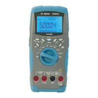
Agilent Technologies U1252A User's Manual And Service Manual (185 pages)
Handheld Digital Multimeter
Brand:
Agilent Technologies
| Category:
Multimeter
| Size: 5.26 MB
Table of Contents
Safety Symbols
3
General Safety Information
4
Safety Information
4
In this Guide
9
Table of Contents
11
1 Getting Started
22
Introducing the U12521A/U1252A Handheld Digital Multimeter
22
Check the Shipment
23
Adjusting the Tilt-Stand
24
Figure 1-1 Tilt-Stand at
24
Figure 1-2 Tilt-Stand at
24
Figure 1-3 Tilt-Stand at Hanging Position
25
Figure 1-4 U1252A Front Panel
26
The Front Panel at a Glance
26
Figure 1-5 Rear Panel
27
The Rear Panel at a Glance
27
Figure 1-6 Rotary Switch
28
Table 1-1 Rotary Switch Description and Functions
28
The Rotary Switch at a Glance
28
Figure 1-7 U1252A Keypad
29
Table 1-2 Keypad Desciption and Functions
29
The Keypad at a Glance
29
Figure 1-8 Display Symbols
31
The Display at a Glance
31
Table 1-3 General Display Symbols
32
Table 1-4 Priamry Display Symbols
33
Table 1-5 Secondary Display Symbols
34
Table 1-6 Analog Bar Range and Counts
35
Selecting Display with the Hz Button
36
Table 1-7 Selecting Display with the Hz Button
36
Selecting Display with the Dual Button
38
Table 1-8 Selecting Display with the Dual Button
38
Selection Display with the Shift Button
40
Table 1-9 Selecting Display with the Shift Button
40
Figure 1-9 U1252A Connector Terminals
42
Table 1-10 Terminal Connections for Different Measuring
42
The Terminals at a Glance
42
2 Making Measurements
43
Figure 2-17 Charge Terminal Alert
43
Measuring Voltage
44
Table 2-1 Numerical Steps Descriptions
44
Figure 2-1 Measuring AC Voltage
45
Measuring AC Voltage
45
Figure 2-2 Measuring DC Voltage
46
Measuring DC Voltage
46
Understanding the Measurement Instructions
44
Measuring Current
47
Μa & Ma Measurement
47
Figure 2-3 Measuring Ma and Ma Current
48
Percentage Scale of 4 Ma to 20 Ma
49
Table 2-2 Percentage Scale and Measurement Range
49
Figure 2-4 Measuring Scale of 4-20 Ma
50
A (Ampere) Measurement
51
Figure 2-5 a (Ampere) Current Measurement
51
Frequency Counter
52
Figure 2-6 Measuring Frequency
53
Figure 2-7 Measuring Resistance
54
Measuring Resistance, Conductance and Testing Continuity
54
Figure 2-8 Audible Continuity, Conductance, and Resistance
55
Table 2-3 Audible Continuity Measurement Range
56
Figure 2-9 Conductance Measurement
57
Testing Diodes
58
Figure 2-10 Measuring Forward Bias of Diode
59
Figure 2-11 Measuring Reverse Bias of Diode
60
Measuring Capacitance
61
Figure 2-12 Capacitance Measurements
62
Measuring Temperature
63
Figure 2-13 Connecting the Thermal Probe into the Non-Compensation Transfer Adapter
64
Figure 2-14 Connecting the Probe with Adapter into the
64
Figure 2-15 Surface Temperature Measurement
66
Alerts and Warning During Measurement
67
Overload Alert
67
Input Warning
67
Figure 2-16 Input Terminal Warning
67
Charge Terminal Alert
68
3 Functions and Features
69
Dynamic Recording
70
Figure 3-1 Dynamic Recording Mode Operation
71
Data Hold (Trigger Hold)
72
Figure 3-2 Data Hold Mode Operation
72
Refresh Hold
73
Figure 3-3 Refresh Hold Mode Operation
74
Null (Relative)
75
Figure 3-4 Null (Relative) Mode Operation
76
Decibel Display
77
Figure 3-5 Dbm/Dbv Display Mode Operation
78
Ms Peak Hold
79
Figure 3-6 1 Ms Peak Hold Mode Operation
80
Data Logging
81
Manual Logging
81
Figure 3-7 Hand (Manual) Logging Mode Operation
82
Figure 3-8 Full Log
82
Interval Logging
83
Figure 3-9 Interval (Automatic) Logging Mode Operation
84
Reviewing Logged Data
85
Figure 3-10 Log Review Mode Operation
86
Square Wave Output (for U1252A)
87
Figure 3-11 Frequency Adjustment for Square Wave Output
88
Figure 3-12 Pulse Width Adjustment for Square Wave Output
89
Figure 3-13 Duty Cycle Adjustment for Square Wave
90
Remote Communication
91
Figure 3-14 Cable Connection for Remote Communication
91
4 Changing the Default Setting
94
Selecting Setup Mode
94
Table 4-1 Available Setting Options in Setup Mode
95
Setting Data Hold/Refresh Hold Mode
97
Figure 4-1 Data Hold/Refersh Hold Setup
97
Setting Data Logging Mode
98
Figure 4-2 Data Logging Setup
98
Setting Thermocouple Types (U1252A Only)
99
Figure 4-3 Thermocouple Type Setup
99
Figure 4-4 Reference Impedance for Dbm Measurement Setup
100
Setting Reference Impedance for Dbm Measurement
100
Figure 4-5 Minimum Frequency Setup
101
Setting Minimum Frequency Measurement
101
Setting Temperature Unit
102
Figure 4-6 Temperature Unit Setup
103
Setting Auto Power Saving Mode
104
Figure 4-7 Auto Power Saving Setup
105
Setting Percentage (%) Scale Readout
106
Figure 4-8 % Scale Readout Setup
106
Figure 4-9 Beep Frequency Setup
107
Setting Beep Frequency
107
Figure 4-10 Backlit Timer Setup
108
Setting Backlight Timer
108
Figure 4-11 Baud Rate Setup Remote Control
109
Setting Baud Rate
109
Setting Parity Check
110
Figure 4-12 Parity Check Setup
110
Setting Data Bit
111
Figure 4-13 Data Bit Setup for Remote Control
111
Setting Echo Mode
112
Figure 4-14 Echo Mode Setup for Remote Control
112
Setting Print Mode
113
Figure 4-15 Print Mode Setup for Remote Control
113
Returning to Default Factory Settings
114
Figure 4-16 Reset Setup
114
5 Maintenance
115
Introduction
116
General Maintenance
116
Battery Replacement
116
Figure 5-1 9 V Rectangular Battery
117
Storage Considerations
118
Charging the Battery
118
Figure 5-2 Battery Capacity Display as Trickle
120
Figure 5-3 Self-Test
120
Table 5-1 Battery Voltage and Corresponding Percentage of Charg
120
Table 5-2 Error Messages
121
Figure 5-4 Charging Mode
122
Figure 5-5 Charge End and Trickle State
123
Figure 5-6 Battery Charging Procedure
124
Fuse Checking Procedure
125
Replacing the Fuse
126
Table 5-3 Measurement Readings for Fuse Checking
126
Figure 5-7 Fuse Replacement
127
Table 5-4 Fuse Specifications
127
Troubleshooting
128
Table 5-5 Basic Troubleshooting Procedures
128
Replaceable Parts
129
To Order Replaceable Parts
129
6 Performance Tests and Calibration
132
Calibration Overview
132
Closed-Case Electronic Calibration
132
Agilent Technologies Calibration Services
132
Calibration Interval
133
Adjustment Is Recommended
133
Recommended Test Equipment
134
Table 6-1 Recommended Test Equipment
134
Basic Operating Test
135
Backlit Test
135
Testing the Display
135
Figure 6-1 LCD Display
135
Current Terminal Test
136
Figure 6-2 Input Warning
136
Charge Terminal Alert Test
137
Figure 6-3 Charge Terminal Alert
137
Test Considerations
138
Calibration Security
139
Performance Verification Tests
140
Table 6-2 Performance Verification Test Steps
141
Unsecuring the Instrument for Calibration
148
Calibration Process
151
Using the Front Panel for Adjustments
152
Adjustments Consideration
153
Valid Adjustment Input Values
154
Table 6-3 Valid Adjustment Input Values
154
Adjustment Procedure
155
Table 6-4 Adjustment Table
157
Finishing the Adjustment
162
To Read the Calibration Count
162
Calibration Errors
163
7 Specifications
165
Product Characteristics
166
Measurement Category
169
Measurement Category Definition
169
Specification Assumptions
170
Electrical Specifications
171
DC Specifications
171
Table 7-1 DC Accuracy ± (% of Reading + Number of Least Signifi- Cant Digit)
172
AC Specifications
173
Table 7-2 U1251A Accuracy Specifications
173
Table 7-3 U1251A Accuracy Specifications
173
Table 7-4 U1252A Accuracy Specifications
174
Table 7-5 U1252A Accuracy Specifications
174
AC+DC Specifications for U1252A
175
Table 7-6 U1252A True RMS Ac+DC Voltage Specifications
175
Table 7-7 U1252A True RMS Ac+DC Current Specifications
175
Capacitance Specifications
176
Temperature Specifications
176
Table 7-8 Capacitance Specifications
176
Table 7-9 Temperature Specifications
176
Frequency Specifications
177
Duty Cycle and Pulse Width Specifications
177
Table 7-10 Frequency Specifications
177
Table 7-11 Duty Cycle and Pulse Width Specifications
177
Frequency Sensitivity Specifications
178
Table 7-12 Frequency Sensitivity and Trigger Level Specifications for
178
Peak Hold Specifications
179
Table 7-13 Frequency Sensitivity Specifications for Current
179
Table 7-14 Peak Hold Specifications for DC Voltage and Current
179
Frequency Counter Specifications for U1252A
180
Table 7-15 Frequency Counter (Divide by 1) Specifications
180
Table 7-16 Frequency Counter
180
Square Wave Output for U1252A
181
Table 7-17 Square Wave Output Specifications
181
Operating Specifications
182
Display Update Rate (Approximate)
182
Table 7-18 Display Update Rate (Approximate)
182
Input Impedance
183
Table 7-19 Input Impedance
183
Advertisement
Agilent Technologies U1252A User Manual (169 pages)
Handheld Digital Multimeter
Brand:
Agilent Technologies
| Category:
Multimeter
| Size: 4.39 MB
Table of Contents
Safety Information
3
Safety Symbols
5
Table of Contents
9
1 Getting Started Tutorial
13
Introducing the Agilent U1251A and U1252A Handheld Digital Multimeter
14
Adjusting the Tilt-Stand
15
The Front Panel at a Glance
17
The Rotary Switch at a Glance
18
The Keypad at a Glance
19
The Display at a Glance
21
Selection of Display by Hz Button
26
Selection of Display by Dual Button
27
Selection of Display by SHIFT Button
30
The Terminals at a Glance
32
The Rear Panel at a Glance
33
2 Making Measurements
35
Measuring Voltage
36
Measuring AC Voltage
36
Measuring DC Voltage
38
Measuring Current
39
Μa & Ma Measurement
39
Μa & Ma Measurement
39
Scale of 4-20 Ma
40
A Measurement
41
Frequency Counter
42
Measuring Resistance, Conductance and Testing Continuity
44
Testing Diodes
48
Measuring Capacitance
51
Measuring Temperature
52
Alerts and Warning During Measurement
55
Overload Alert
55
Input Warning
55
Charge Terminal Alert
56
3 Features and Functions
57
Dynamic Recording
58
Data Hold (Trigger Hold)
60
Refresh Hold
61
NULL (Relative)
63
Decibel Display
65
Ms Peak Hold
67
Data Logging
69
Manual Logging
69
Interval Logging
71
Reviewing Logged Data
73
Square Wave Output (for U1252A)
75
Remote Communication
79
4 Changing the Default Setting
81
Selecting Setup Mode
82
Setting Data Logging Mode
86
Setting Thermocouple Types (for U1252A)
87
Setting Reference Impedance for Dbm Measurement
88
Setting Minimum Frequency Measurement
89
Setting Temperature Unit
90
Setting Auto Power Saving Mode
92
Setting % Scale Readout
94
Setting Beep Frequency
95
Setting Backlit Timer
96
Setting Baud Rate
97
Setting Parity Check
98
Setting Data Bit
99
Setting Echo Mode
100
Setting Print Mode
101
Returning to Default Factory Settings
102
5 Maintenance
103
Introduction
104
General Maintenance
104
Replacing the Battery
105
Charging the Battery
107
Measuring DC Voltage
111
Measuring Current
112
Fuse Checking Procedure
113
Replacing the Fuse
114
Troubleshooting
116
6 Accessories
117
Checking the Shipping Contents
118
List of Accessories
119
7 Performance Tests and Calibration
121
Calibration Overview
122
Closed - Case Electronic Calibration
122
Agilent Technologies Calibration Services
122
Calibration Interval
122
Adjustment Is Recommended
123
Recommended Test Equipment
124
Basic Operating Test
125
Backlit Test
125
Testing the Display
125
Current Terminal Test
126
Charge Terminal Alert Test
127
Test Considerations
128
Input Connections
129
Performance Verification Tests
130
Calibration Security
138
Unsecuring the Instrument for Calibration
139
Calibration Process
142
Using the Front Panel for Adjustments
143
Adjustments Consideration
144
Valid Adjustment Input Values
145
Adjustment Procedure
146
Finishing the Adjustment
153
To Read the Calibration Count
153
Calibration Errors
154
8 Specifications
155
DC Specifications
156
U1251A AC Specifications
158
U1252A AC Specifications
159
U1252A AC+DC Specifications
160
Temperature and Capacitance Specifications
161
U1251A & U1252A Frequency Specifications(1)
162
Operating Specifications
165
General Specifications
166
Agilent Technologies U1252A User's And Service Manual (168 pages)
Handheld Digital Multimeter
Brand:
Agilent Technologies
| Category:
Multimeter
| Size: 4.94 MB
Table of Contents
Table of Contents
9
1 Getting Started Tutorial
13
Introducing the Agilent U1251A and U1252A Handheld Digital Multimeter
14
Adjusting the Tilt-Stand
15
The Front Panel at a Glance
17
The Rotary Switch at a Glance
18
The Keypad at a Glance
19
The Display at a Glance
21
Selection of Display by Hz Button
25
Selection of Display by Dual Button
27
Selection of Display by SHIFT Button
30
The Terminals at a Glance
32
The Rear Panel at a Glance
33
2 Making Measurements
35
Measuring Voltage
36
Measuring AC Voltage
36
Measuring DC Voltage
38
Measuring Current
39
Μa & Ma Measurement
39
Μa & Ma Measurement
39
Scale of 4-20 Ma
40
A Measurement
41
Frequency Counter
42
Measuring Resistance, Conductance and Testing Continuity
44
Testing Diodes
48
Measuring Capacitance
51
Measuring Temperature
52
Alerts and Warning During Measurement
55
Overload Alert
55
Input Warning
55
Charge Terminal Alert
56
3 Features and Functions
57
Dynamic Recording
58
Data Hold (Trigger Hold)
60
Refresh Hold
61
NULL (Relative)
63
Decibel Display
65
Ms Peak Hold
67
Data Logging
69
Manual Logging
69
Interval Logging
71
Reviewing Logged Data
73
Square Wave Output (for U1252A)
75
Remote Communication
79
Remote Communication
80
4 Changing the Default Setting
81
Selecting Setup Mode
82
Setting Data Logging Mode
86
Setting Thermocouple Types (for U1252A)
87
Setting Reference Impedance for Dbm Measurement
88
Setting Minimum Frequency Measurement
89
Setting Temperature Unit
90
Setting Auto Power Saving Mode
92
Setting % Scale Readout
94
Setting Beep Frequency
95
Setting Backlit Timer
96
Setting Baud Rate
97
Setting Parity Check
98
Setting Data Bit
99
Setting Echo Mode
100
Setting Print Mode
101
Returning to Default Factory Settings
102
5 Maintenance
103
Introduction
104
General Maintenance
104
Battery Replacement
105
Charging Battery
106
Fuse Replacement
113
Troubleshooting
115
6 Accessories
117
Checking the Shipping Contents
118
List of Accessories
119
7 Performance Tests and Calibration
121
Calibration Overview
122
Closed - Case Electronic Calibration
122
Agilent Technologies Calibration Services
122
Calibration Interval
122
Adjustment Is Recommended
123
Recommended Test Equipment
124
Basic Operating Test
125
Backlit Test
125
Testing the Display
125
Current Terminal Test
126
Charge Terminal Alert Test
127
Test Considerations
128
Input Connections
129
Performance Verification Tests
130
Calibration Security
138
Unsecuring the Instrument for Calibration
139
Calibration Process
142
Using the Front Panel for Adjustments
143
Adjustments Consideration
144
Valid Adjustment Input Values
145
Adjustment Procedure
146
Finishing the Adjustment
153
To Read the Calibration Count
153
Calibration Errors
154
8 Specifications
155
DC Specifications
158
U1251A AC Specifications
160
U1252A AC Specifications
161
U1252A AC+DC Specifications
162
Temperature and Capacitance Specifications
163
U1251A & U1252A Frequency Specifications(1)
164
Operating Specifications
167
General Specifications
168
Advertisement
Agilent Technologies U1252A Quick Start Manual (6 pages)
Handheld Digital Multimeter
Brand:
Agilent Technologies
| Category:
Multimeter
| Size: 1.26 MB
Table of Contents
Performing Voltage Measurement
2
Performing Current Measurement
2
Performing Capacitance and Temperature Measurements
3
Frequency and Frequency Counter Measurements
4
Features and Functions
5
Input Terminals and Overload Protection
5
Safety Information
6
Safety Symbols
6
Advertisement
Related Products
Agilent Technologies U1252B
Agilent Technologies U1251B
Agilent Technologies U1251A
Agilent Technologies U1253B
Agilent Technologies U1253A
Agilent Technologies U1242A
Agilent Technologies U1231A
Agilent Technologies U1242B
Agilent Technologies U1241B
Agilent Technologies U1273AX
Agilent Technologies Categories
Measuring Instruments
Laboratory Equipment
Test Equipment
Water Pump
Power Supply
More Agilent Technologies Manuals
Login
Sign In
OR
Sign in with Facebook
Sign in with Google
Upload manual
Upload from disk
Upload from URL