Sign In
Upload
Manuals
Brands
ADTRAN Manuals
Network Hardware
Total Access 362R
ADTRAN Total Access 362R Manuals
Manuals and User Guides for ADTRAN Total Access 362R. We have
4
ADTRAN Total Access 362R manuals available for free PDF download: Installation And Maintenance Manual, Manual
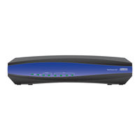
ADTRAN Total Access 362R Installation And Maintenance Manual (138 pages)
Single Family Unit ONT
Brand:
ADTRAN
| Category:
Network Hardware
| Size: 6.16 MB
Table of Contents
Table of Contents
7
Introduction
15
Scope of this Guide
15
In this Guide
15
Table Intro-1. Topic List
15
Related Online Documents and Resources
16
Table Intro-2. Related Online Documents and Resources
16
Section 1
19
Single Family Unit ONT
19
Scope of this Section
19
In this Section
19
GPON Technology
19
Table 1-1. Topic List
19
Total Access 300 Series ONT
21
Table 1-2. Onts
21
Table 1-3. Part Numbers and CLEI Codes
21
Features
22
Figure 1-1. Total Access 324 ONT
22
Total Access 324 Single Family Unit ONT
22
Features
23
Figure 1-2. Total Access 324 ONT with UPS
23
Total Access 324 Single Family Unit ONT with UPS
23
Features
24
Figure 1-3. Total Access 334 3Rd Generation SFU with Overlay and UPS SFU ONT
24
Total Access 334 3Rd Generation Single Family Unit ONT with RF Overlay
24
Features
25
Figure 1-4. Total Access 351 SFU ONT
25
Total Access 351 Single Family Unit ONT
25
Features
26
Figure 1-5. Total Access 352 SFU ONT
26
Total Access 352 Single Family Unit ONT
26
Features
27
Figure 1-6. Total Access 352H SFU ONT
27
Total Access 352H 2Nd Generation Single Family Unit ONT
27
Hpna
28
Features
29
Figure 1-7. Total Access 361 SFU ONT
29
Total Access 361 Single Family Unit ONT
29
Features
30
Figure 1-8. Total Access 362 SFU ONT
30
Total Access 362 Single Family Unit ONT
30
Features
31
Figure 1-9. Total Access 362R SFU ONT
31
Total Access 362R Single Family Unit ONT
31
Features
32
Figure 1-10. Total Access 364 2 POTS/4 Ethernet/1 RF Overlay Outdoor ONT
32
Total Access 364 2 POTS/4 Ethernet/1 RF Overlay Outdoor ONT
32
Total Access 300 Series Housings and Bracket
33
Figure 1-11. Corning NID Housings
33
Figure 1-12. Indoor Unrestricted Access Mounting Bracket
34
Section 2
35
Single Family Unit Indoor Installation
35
Scope of this Section
35
In this Section
35
Table 2-1. Single Family Unit ONT
35
Table 2-2. Topic List
35
Description
36
Safety and Regulatory Compliance
36
Installation
38
Required Tools and Supplies
38
Mount the ONT
38
Desktop Mounting
38
Total Access 334 3Rd Generation ONT Mounting
38
Figure 2-1. ONT Indoor Wall Mount
39
Wall Mounting
39
POTS Connection
40
Ethernet Connection
40
Figure 2-2. ONT Rear Panel
40
Table 2-3. Ethernet Cable Pin-Outs
40
Fiber Optics Connection
41
Fiber Optics Connection for Total Access 334 3Rd Generation ONT
41
Figure 2-3. Total Access 334 3Rd Generation ONT Rear Panel
41
RF Video
42
Figure 2-4. ONT Rear Panel
42
Total Access 334 3Rd Generation RF Video
42
External Power Supply
43
Figure 2-5. UPS Power Connection
43
Connecting UPS
44
Figure 2-6. Molex UPS Connector
44
Figure 3-6. UPS
44
Table 2-4. UPS Pin-Out Connection
44
Total Access 334 3Rd Generation ONT UPS
44
Total Access 334 3Rd Generation AC Adaptor Power Supply
45
Table 2-5. Total Access 334 3Rd Generation UPS Pin-Out Connection
45
Total Access 324 Front Panel Leds
46
Table 2-6. Total Access 324 Front Panel Leds
46
Total Access 334 3Rd Generation ONT Front Panel Leds
47
Table 2-7. Total Access 334 3Rd Generation ONT Front Panel Leds
47
Operational Specifications
48
Table 2-8. Specifications
48
Section 3
49
Single Family Unit Outdoor Installation
49
Scope of this Section
49
In this Section
49
Table 3-1. Single Family Unit ONT
49
Table 3-2. Topic List
49
Description
50
Figure 3-1. Typical Outdoor ONT
50
Safety and Regulatory Compliance
51
Components and Interfaces
53
Network Interface Device
53
Outer Enclosure
53
Outer Enclosure Security Locking Feature
53
Figure 3-2. NID Housing with Security Features
54
Figure 3-3. ONT Splice Housing
55
Figure 3-4. ONT Optitap Housing
55
Total Access 350 ONT NID Optitap Housing
55
Total Access 350 ONT NID Splice Housing
55
Electronics Module
56
Figure 3-5. Total Access 300 Series Electronics Module
56
Circuit Board
57
Data Processing
57
Voice Processing
57
Alarm Reporting
58
ONT Interfaces
58
GPON Interface
58
Ethernet Interface
58
POTS Interface
58
HPNA Interface
59
RF Interface
59
UPS Power Supply
59
Installation
60
Shipping Contents
60
Required Tools
60
Necessary Supplies
61
Instructions for Installing the SFU ONT
62
Figure 3-7. Exterior ONT Installation
62
Determining ONT Enclosure Location
63
Accessing the Inner Electronics Module
64
Figure 3-8. Total Access 362R Accessing Inner Electronics Module
64
Figure 3-9. Housing Mounting Holes
65
Mounting the Enclosure
65
Figure 3-10. Wire Routing
66
Wire Routes
66
Fiber Drop Cable Route
67
Figure 3-11. Optitap Connector Installation
67
Figure 3-12. Bulk Head Adapter
68
Figure 3-13. Cable Ground Installation
69
Ground Wire Connection
69
Figure 3-14. ONT Ground Connection
70
Alternative Grounding Method
71
Local Power Source Wire Run
71
Figure 3-15. Power/Alarm and UPS Connectors
72
ONT Power/Alarm Connector
72
Table 3-3. Power/Alarm Connector Pinout
72
Figure 3-16. Power/Alarm Connector on Back of Electronics Module
73
Figure 3-17. Power/Alarm Wire Routing
73
Figure 3-18. Power/Alarm Connector Installed
74
Installation of the UPS Power Supply
74
Figure 3-19. UPS Power Connection
75
SC/APC Fiber Drop Cable Installation
76
Table 3-4. UPS Pin-Out Connection
76
Figure 3-20. SC/APC Fiber Installation
77
Figure 3-21. Optitap Installation
78
Optitap Fiber Drop Cable Installation
78
POTS Connections
79
Subscriber Connections
79
Ethernet Connection
80
Figure 3-22. Total Access 300 Series POTS and Ethernet Connections
80
Table 3-5. Ethernet Cable Pin-Outs
80
Figure 3-23. Total Access 362R Final Installation Example
82
RF Connection
82
Commissioning and Testing
83
Turn-Up
83
Front Panel Leds
83
Table 3-6. Front Panel Leds
83
Secure the Unit
84
Test for POTS Line Faults
84
Provision POTS and Ethernet Interface at OLT
84
Maintenance
85
Specifications
85
Table 3-7. Specifications
85
Section 4
87
Scope of this Section
87
In this Section
87
Table 4-1. Section 2 Topics
87
Unrestricted Access Installation
87
Description
88
Figure 4-1. Electronics Module and Bracket
88
Safety and Regulatory Compliance
89
Installation
91
Shipping Contents
92
Necessary Supplies
92
ONT Bracket Installation
92
Determining Location
92
Figure 4-2. Power/Alarm and UPS Connectors
93
ONT Power/Alarm Connector
93
Figure 4-3. Power/Alarm Connector
94
Table 4-2. Power/Alarm Connector Pinout
94
Figure 4-4. Power/Alarm Connector Installed
95
Figure 4-5. UPS Power Connection
96
Installation of the UPS Power Supply
96
Table 4-3. UPS Pin-Out Connection
97
Figure 4-6. Optitap Connector Installation
98
Optitap Installation
98
Figure 4-7. Fiber Connections
99
Figure 4-8. Fiber Installation Without Optitap
100
Installation Without Optitap
100
POTS Connections
101
Subscriber Connections
101
Table 4-4. POTS RJ-11 Pin-Outs
101
Ethernet Connection
102
Table 4-5. Ethernet Cable Pin-Outs
102
Figure 4-9. Subscriber Connections
103
RF Connection
103
Commissioning and Testing
104
Turn-Up
104
Front Panel Leds
104
Table 4-6. Front Panel Leds
104
Test for POTS Line Faults
105
Provision POTS and Ethernet Interface at OLT
105
Maintenance
106
Specifications
106
Table 4-7. Specifications
106
Section 5
107
Multi-Dwelling Unit Installation
107
Scope of this Section
107
In this Section
107
Table 5-1. Section 5 Topics
107
Description
108
Figure 5-1. MDU Housing
108
Safety and Regulatory Compliance
109
Installation
111
Shipping Contents
111
Necessary Supplies
112
Instructions for Installing the MDU
113
Figure 5-2. Exterior ONT Installation
113
Determining MDU Enclosure Location
114
Figure 5-3. MDU Ground Connection
115
Grounding the MDU
115
Connecting Power to the MDU Housing
116
Figure 5-4. Printed Circuit Board
116
Figure 5-5. P5 Terminal Block
116
Figure 5-6. Secure Electronics Module
117
Install Electronics Module
117
Figure 5-7. Electronics Module Installation
118
Figure 5-8. Wire Route
119
Figure 5-9. Terminal Block Wire Connections
119
Figure 5-10. Electronics Module Install
120
Figure 5-11. Optitap Connector Installation
121
Figure 5-12. Optitap Installation
122
Figure 5-13. Fiber Splitter Installation
123
Provisioning Options
124
Figure 5-14. MDU Splitter
124
Specifications
125
Table 5-2. Specifications
125
Section 6
127
Troubleshooting
127
Scope of this Section
127
In this Section
127
Table 6-1. Section 6 Topics
127
Troubleshooting
128
Faults Indicated with Leds
129
Leds in Fault State
129
Leds in Normal State
129
ONT Trouble Isolation
129
Additional Troubleshooting Steps
130
Network Status LED
130
Table 6-2. Power Leds
130
Table 6-3. Power Leds
130
UPS Power Leds
130
POTS Troubleshooting
131
ODN Interface Troubleshooting
131
Figure 6-1. Network LED Flowchart
131
Cleaning and Inspection of Components
132
Cleaning Suggestions
132
Figure 6-2. ONT Fiber Connection
132
Cleaning the Bulkhead
133
Cleaning the Connectors
133
Downstream Signal Level Verification
133
Signal Level Verification
133
Table 6-4. Downstream Power Levels
133
Figure 6-3. Downstream Test Configuration
134
Table 6-5. Upstream Power Levels
134
Upstream Signal Level Verification
134
UPS Communication Signals
135
Figure 6-4. Upstream Test Configuration
135
Table 6-6. UPS Communication Signal Descriptions
135
Maintenance
136
Appendix A
137
Appendix A Warranty and Customer Support
137
Warranty
137
Contact Information
137
Advertisement
ADTRAN Total Access 362R Installation And Maintenance Manual (62 pages)
Single Family Unit with RF Return
Brand:
ADTRAN
| Category:
Network Hardware
| Size: 2.97 MB
Table of Contents
Table of Contents
7
Scope of this Guide
11
In this Guide
11
Topic List
11
Related Documentation
12
Table 2. Related Documentation
12
Description
13
GPON Technology
13
Figure 1. Total Access 362R SFU ONT
13
Features
14
Modules and Housings
15
Table 3. 362R Modules and Housings
15
Safety and Regulatory Compliance
16
Components and Interfaces
18
Mechanical Components
18
Outer Enclosure
18
Outer Enclosure Security Locking Feature
18
Figure 2. Security Features
19
Outer Enclosure W/Cover Removed
20
Figure 3. Enclosure with Cover and Electronics Module Removed
20
Electronics Module
21
Figure 4. Electronics Module
21
Circuit Board
22
Data Processing
22
Voice Processing
22
Alarm Reporting
23
ONT Interfaces
23
GPON Interface
23
Ethernet Interface
23
POTS Interface
23
RF Interface
24
UPS Power Supply
24
Figure 5. Uninterruptible Power Supply (UPS)
24
Installation
25
Shipping Contents
25
Required Tools
25
Necessary Supplies
26
Instructions for Installing the SFU ONT
27
Figure 6. Typical ONT Installation
27
Determining ONT Enclosure Location
28
Accessing the Inner Electronics Module
29
Figure 7. Accessing the Inner Electronics Module
29
Mounting the Enclosure
30
Figure 8. Enclosure Mounting Holes
30
Wire Routes
31
Figure 9. Wire Routing
31
Fiber Drop Cable Route
32
Figure 10. Optitap Adapter Installation
32
Figure 11. Bulk Head Adapter
33
Grounding the Buried Fiber
34
Ground Wire Connection
34
Figure 12. Cable Ground Installation
34
Figure 13. ONT Ground Connection
35
Alternative Grounding Method
36
Local Power Source Wire Run
36
SFU ONT Power/Alarm Connector
37
Figure 14. Power/Alarm and UPS Connectors
37
Table 4. Power/Alarm Connector Pinout
37
Figure 15. Power/Alarm Connector
38
Figure 16. Power/Alarm Wire Routing
38
Figure 17. Euro Connector Installed
39
Installation of the Power Supply
40
Figure 18. UPS Power Connection
40
Table 5. UPS Pin-Out Connection
41
SC/APC Fiber Drop Cable Installation
42
Figure 19. SC/APC Fiber Installation
42
Optitap Fiber Drop Cable Installation
43
Figure 20. Optitap Installation
43
Figure 21. Wire Routing
44
Subscriber Connections
45
POTS Connections
45
Figure 22. POTS and Ethernet Connections
45
Ethernet Connection
46
Table 6. Ethernet Cable Pin-Outs
46
RF Connection
47
Figure 23. Final Installation Example
47
Commissioning and Testing
48
Turn-Up
48
Front Panel Leds
49
Secure the Unit
49
Test for POTS Line Faults
49
Table 7. Front Panel Leds
49
Provision Ethernet Interface at OLT
50
Troubleshooting
50
Faults Indicated with Leds
51
Leds in Normal State
51
Leds in Fault State
51
ONT Trouble Isolation
51
UPS Power Leds
52
Table 8. Power Leds
52
Network Status LED off
53
Figure 24. Network LED Flowchart
53
POTS Troubleshooting
54
ODN Interface Troubleshooting
54
Cleaning and Inspection of Components
54
Figure 25. ONT Fiber Connection
54
Cleaning Suggestions
55
Cleaning the Connectors
55
Cleaning the Bulkhead
55
Signal Level Verification
55
Downstream Signal Level Verification
56
Figure 26. Downstream Test Configuration
56
Table 9. Downstream Power Levels
56
Upstream Signal Level Verification
57
Figure 27. Upstream Test Configuration
57
Table 10. Upstream Power Levels
57
UPS Communication Signals
58
Table 11. UPS Communication Signal Descriptions
58
Maintenance
59
Specifications
60
Table 12. Specifications
60
Warranty and Customer Support
61
Warranty
61
ADTRAN Customer Care
61
ADTRAN Sales
61
ADTRAN Technical Support
61
ADTRAN Repair/Caps
61
Repair and Return Address
61
ADTRAN Total Access 362R Manual (4 pages)
Single Family Unit ONT
Brand:
ADTRAN
| Category:
Network Hardware
| Size: 1 MB
Advertisement
ADTRAN Total Access 362R Manual (4 pages)
Single Family Unit with RF Return
Brand:
ADTRAN
| Category:
Network Hardware
| Size: 0.64 MB
Advertisement
Related Products
ADTRAN Total Access 361
ADTRAN Total Access 362
ADTRAN Total Access 364
ADTRAN NetVanta 3120 with DBU
ADTRAN Total Access 352
ADTRAN Total Access 352H
ADTRAN Total Access 324E
ADTRAN Total Access 354E
ADTRAN Total Access 372R
ADTRAN Total Access 372
ADTRAN Categories
Network Hardware
Network Router
Switch
Control Unit
Gateway
More ADTRAN Manuals
Login
Sign In
OR
Sign in with Facebook
Sign in with Google
Upload manual
Upload from disk
Upload from URL