Sign In
Upload
Manuals
Brands
ADTRAN Manuals
Network Hardware
Total Access 372R
ADTRAN Total Access 372R Manuals
Manuals and User Guides for ADTRAN Total Access 372R. We have
1
ADTRAN Total Access 372R manual available for free PDF download: Installation And Maintenance Manual
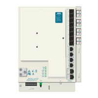
ADTRAN Total Access 372R Installation And Maintenance Manual (72 pages)
Small Business Unit ONT
Brand:
ADTRAN
| Category:
Network Hardware
| Size: 3.47 MB
Table of Contents
Table of Contents
7
Introduction
13
Scope of this Guide
13
In this Guide
13
Table Intro-1. Topic List
13
Related Documentation
14
Table Intro-2. Related Documentation
14
Section 1
15
Small Business Unit ONT
15
Scope of this Section
15
In this Section
15
Table 1-1. Topic List
15
GPON Technology
16
Total Access 300 Series ONT
17
Table 1-2. Onts
17
Total Access 372
18
Features
18
Figure 1-1. Total Access 372 ONT
18
Total Access 372R with RF Overlay
19
Features
19
Figure 1-2. Total Access 372R ONT with RF Overlay
19
Safety and Regulatory Compliance
20
Components and Interfaces
22
Mechanical Components
22
Outer Enclosure
22
Outer Enclosure Security Locking Feature
22
Figure 1-3. Total Access 372R Enclosure and Electronics Module
23
Outer Enclosure with Cover Removed
23
Electronics Module
24
Figure 1-4. Total Access 372R Electronics Module
24
Circuit Board
25
Data Processing
25
Voice Processing
25
Alarm Reporting
26
ONT Interfaces
26
Ethernet Interface
26
POTS Interface
26
RF Interface
27
UPS Power Supply
27
Figure 1-5. Uninterruptible Power Supply (UPS)
27
Section 2
29
Small Business Unit Installation
29
Scope of this Section
29
In this Section
29
Table 2-1. Small Business Unit ONT
29
Table 2-2. Topic List
29
Installation
30
Shipping Contents
30
Required Tools
31
Necessary Supplies
31
Instructions for Installing the SBU ONT
32
Figure 2-1. Typical ONT Installation
32
Determining ONT Enclosure Location
33
Figure 2-2. Enclosure Mounting Holes
35
Mounting the Enclosure Outdoors
35
Figure 2-3. Installing the Electronics Module
36
Install the Electronics Module
36
Completed Outdoor SBU ONT Installation
37
Figure 2-4. Completed Installation
37
Figure 2-5. Cable Ground Installation
38
Ground Wire Connection
38
Figure 2-6. ONT Ground Connection
39
Alternative Grounding Method
40
Local Power Source Wire Run
40
Figure 2-7. ONT Power and UPS Connectors
41
ONT Power Connector
41
Table 2-3. Connector Pinout
41
Figure 2-8. Power/Alarm Connector
42
Figure 2-9. UPS Power Connection
43
Installation of the Power Supply
43
Table 2-4. UPS Pin-Out Connection
44
Fiber Tray Installation
45
Figure 2-10. Fiber Tray Installation
45
Subscriber Connections
45
Figure 2-11. POTS Connections
46
POTS Connections
46
Figure 2-12. Ethernet and DS1 Cable Connections
47
Install Ethernet Connections
47
Table 2-5. Ethernet Cable Pin-Outs
48
Table 2-6. Ethernet Leds
48
Install DS1 Connections
49
Table 2-7. DS1 Cable Pin-Outs
49
Figure 2-13. Fiber Installation
50
Install Fiber to the Unit
50
Figure 2-14. Coaxial Cable Installation
51
Install RF Overlay
51
Figure 2-15. Optitap Installation
52
Optitap Installation
52
Figure 2-16. Optitap Installation
53
Figure 2-17. Indoor Mounting
54
Mounting the Electronics Module Indoors
54
Figure 2-18. Tie Wrap Cables
55
Installed Indoor Electronics Module
55
Figure 2-19. Optitap Routing
56
Commissioning and Testing
57
Turn-Up
57
Front Panel Leds
58
Secure the Unit
58
Table 2-8. Front Panel Leds
58
Test for POTS Line Faults
59
Provision Ethernet Interface at OLT
59
Section 3
61
Troubleshooting
61
Scope of this Section
61
In this Section
61
Table 3-1. Section 2 Topics
61
Troubleshooting
62
Faults Indicated with Leds
62
Leds in Normal State
62
Leds in Fault State
63
ONT Trouble Isolation
63
NET Status LED off
63
Table 3-2. Power Leds
63
UPS Power Leds
63
Figure 3-1. Network LED Flowchart
64
Cleaning and Inspection of Components
65
Cleaning Suggestions
65
Cleaning the Connectors
65
POTS Troubleshooting
65
Downstream Signal Level Verification
66
Figure 3-2. Downstream Test Configuration
66
Signal Level Verification
66
Table 3-3. Downstream Power Level
66
Figure 3-3. Upstream Test Configuration
67
Table 3-4. Upstream Power Levels
67
Upstream Signal Level Verification
67
UPS Communication Signals
68
Maintenance
68
Table 3-5. UPS Communication Signal Descriptions
68
Specifications
69
Table 3-6. Specifications
69
Appendix A
71
Appendix A Warranty and Customer Support
71
Warranty
71
ADTRAN Customer Care
71
ADTRAN Sales
71
ADTRAN Technical Support
71
ADTRAN Repair/Caps
71
Repair and Return Address
71
Advertisement
Advertisement
Related Products
ADTRAN Total Access 372
ADTRAN 3.125 Gigabit Ethernet
ADTRAN NetVanta 3120 with DBU
ADTRAN Total Access 324
ADTRAN Total Access 351
ADTRAN Total Access 352
ADTRAN Total Access 361
ADTRAN Total Access 362
ADTRAN Total Access 362R
ADTRAN Total Access 364
ADTRAN Categories
Network Hardware
Network Router
Switch
Control Unit
Gateway
More ADTRAN Manuals
Login
Sign In
OR
Sign in with Facebook
Sign in with Google
Upload manual
Upload from disk
Upload from URL