Sign In
Upload
Manuals
Brands
ABB Manuals
Relays
Relion REC670
ABB Relion REC670 Manuals
Manuals and User Guides for ABB Relion REC670. We have
18
ABB Relion REC670 manuals available for free PDF download: Applications Manual, Commissioning Manual, Product Manual, Operator's Manual, Installation Manual, Communication Protocol Manual
ABB Relion REC670 Applications Manual (482 pages)
Bay control Version 2.1 IEC
Brand:
ABB
| Category:
Control Unit
| Size: 7.37 MB
Table of Contents
Table of Contents
7
Introduction
23
This Manual
23
Intended Audience
23
Section 1 Introduction
23
Product Documentation
24
Product Documentation Set
24
Document Revision History
25
Related Documents
25
Document Symbols and Conventions
26
Symbols
26
Document Conventions
27
IEC61850 Edition 1 / Edition 2 Mapping
27
Application
35
General IED Application
35
Section 2 Application
35
Main Protection Functions
36
Back-Up Protection Functions
36
Control and Monitoring Functions
38
Communication
43
Basic IED Functions
46
Configuration
49
Introduction
49
Section 3 Configuration
49
Description of Configuration REC670
50
Introduction
50
Description of Configuration A30
50
Description of Configuration A31
51
Description of Configuration B30
52
Description of Configuration C30
53
Analog Inputs
57
Introduction
57
Setting Guidelines
57
Setting of the Phase Reference Channel
57
Section 4 Analog Inputs
57
Example
58
Setting of Current Channels
58
Example 1
58
Example 2
59
Example 3
60
Examples on How to Connect, Configure and Set CT Inputs for most Commonly Used CT Connections
64
Example on How to Connect a Star Connected Three-Phase CT Set to the IED
65
Example How to Connect Delta Connected Three-Phase CT Set to the IED
68
Example How to Connect Single-Phase CT to the IED
70
Relationships between Setting Parameter Base Current, CT Rated Primary Current and Minimum Pickup of a Protection IED
71
Setting of Voltage Channels
72
Example
72
Examples How to Connect, Configure and Set VT Inputs for most Commonly Used VT Connections
72
Examples on How to Connect a Three Phase-To-Earth Connected VT to the IED
73
Example on How to Connect a Phase-To-Phase Connected VT to the IED
75
Example on How to Connect an Open Delta VT to the IED for High Impedance Earthed or Unearthed Netwoeks
77
Example How to Connect the Open Delta VT to the IED for Low Impedance Earthed or Solidly Earthed Power Systems
78
Example on How to Connect a Neutral Point VT to the IED
80
Local HMI
83
Section 5 Local HMI
83
Display
84
Leds
85
Keypad
86
Local HMI Functionality
88
Protection and Alarm Indication
88
Front Communication
89
Parameter Management
89
Differential Protection
91
High Impedance Differential Protection, Single Phase HZPDIF
91
Identification
91
Application
91
Section 6 Differential Protection
91
The Basics of the High Impedance Principle
93
Connection Examples for High Impedance Differential Protection
98
Connections for Three-Phase High Impedance Differential Protection
98
Connections for 1Ph High Impedance Differential Protection HZPDIF
99
Setting Guidelines
100
Configuration
100
Settings of Protection Function
100
T-Feeder Protection
100
Tertiary Reactor Protection
103
Alarm Level Operation
105
Current Protection
107
Instantaneous Phase Overcurrent Protection PHPIOC
107
Identification
107
Application
107
Setting Guidelines
107
Section 7 Current Protection
107
Meshed Network Without Parallel Line
108
Meshed Network with Parallel Line
110
Four Step Phase Overcurrent Protection OC4PTOC
111
Identification
111
Application
111
Setting Guidelines
112
Settings for each Step
113
2Nd Harmonic Restrain
116
Instantaneous Residual Overcurrent Protection EFPIOC
120
Identification
121
Application
121
Setting Guidelines
121
Four Step Residual Overcurrent Protection, (Zero Sequence or Negative Sequence Directionality) EF4PTOC
123
Identification
123
Application
123
Setting Guidelines
125
Settings for each Step (X = 1, 2, 3 and 4)
125
Common Settings for All Steps
127
2Nd Harmonic Restrain
128
Parallel Transformer Inrush Current Logic
128
Switch Onto Fault Logic
129
Line Application Example
130
Four Step Directional Negative Phase Sequence Overcurrent Protection NS4PTOC
134
Identification
134
Application
134
Setting Guidelines
136
Settings for each Step
136
Common Settings for All Steps
138
Sensitive Directional Residual Overcurrent and Power Protection SDEPSDE
139
Identification
139
Application
140
Setting Guidelines
141
Thermal Overload Protection, One Time Constant, Celsius/Fahrenheit LCPTTR/LFPTTR
148
Identification
148
Application
148
Setting Guideline
149
Thermal Overload Protection, Two Time Constants TRPTTR
150
Identification
150
Application
150
Setting Guideline
151
Breaker Failure Protection CCRBRF
153
Identification
153
Application
153
Setting Guidelines
153
Stub Protection STBPTOC
156
Identification
156
Application
156
Setting Guidelines
157
Pole Discordance Protection CCPDSC
157
Identification
158
Application
158
Setting Guidelines
158
Directional Underpower Protection GUPPDUP
159
Identification
159
Application
159
Setting Guidelines
161
Directional Overpower Protection GOPPDOP
164
Identification
164
Application
164
Setting Guidelines
166
Broken Conductor Check BRCPTOC
169
Identification
169
Application
169
Setting Guidelines
169
Capacitor Bank Protection CBPGAPC
169
Identification
170
Application
170
SCB Protection
172
Setting Guidelines
173
Restrike Detection
175
Voltage-Restrained Time Overcurrent Protection VRPVOC
175
Identification
175
Application
176
Base Quantities
176
Application Possibilities
176
Undervoltage Seal-In
177
Setting Guidelines
177
Explanation of the Setting Parameters
177
Voltage-Restrained Overcurrent Protection for Generator and Step-Up Transformer
178
Overcurrent Protection with Undervoltage Seal-In
179
Advertisement
ABB Relion REC670 Applications Manual (658 pages)
Relion 670 Series, Bay Control
Brand:
ABB
| Category:
Control Unit
| Size: 11.38 MB
Table of Contents
Table of Contents
7
Section 1 Introduction
27
This Manual
27
Intended Audience
27
Product Documentation
28
Product Documentation Set
28
Document Revision History
29
Related Documents
30
Document Symbols and Conventions
30
Symbols
30
Document Conventions
31
IEC 61850 Edition 1 / Edition 2 Mapping
32
Section 2 Application
43
General IED Application
43
Main Protection Functions
44
Back-Up Protection Functions
45
Control and Monitoring Functions
46
Communication
54
Basic IED Functions
57
Section 3 Configuration
59
Description of Configuration REC670
59
Introduction
59
Description of Configuration A30
59
Description of Configuration B30
61
Description of Configuration C30
63
Description of Configuration D30
65
Section 4 Analog Inputs
67
Introduction
67
Setting Guidelines
67
Setting of the Phase Reference Channel
67
Example
68
Setting of Current Channels
68
Example 1
69
Example 2
69
Example 3
70
For most Commonly Used CT Connections
73
Example on How to Connect a Wye Connected Three-Phase CT Set to the IED
74
Example How to Connect Delta Connected Three-Phase CT Set to the IED
79
Example How to Connect Single-Phase CT to the IED
82
Relationships between Setting Parameter Base Current, CT Rated Primary Current and Minimum Pickup of a Protection IED
84
Example
85
Examples on How to Connect a Three Phase-To-Ground Connected VT to the IED
86
Example on How to Connect a Phase-To-Phase Connected VT to the IED
88
Example on How to Connect an Open Delta VT to the IED for High Impedance Grounded or Ungrounded Networks
90
Example How to Connect the Open Delta VT to the IED for Low Impedance Grounded or Solidly Grounded Power Systems
93
Section 5 Local HMI
97
Display
98
Leds
101
Keypad
102
Local HMI Functionality
104
Parameter Management
105
Front Communication
106
C37.118 Phasor Measurement Data Streaming Protocol Configuration PMUCONF
107
Short Guidance for Use of TCP
108
Short Guidance for Use of UDP
109
Protocol Reporting Via IEEE 1344 and C37.118 PMUREPORT
111
Application
112
Operation Principle
114
Frequency Reporting
116
Reporting Filters
118
Scaling Factors for ANALOGREPORT Channels
119
PMU Report Function Blocks Connection Rules in PCM600 Application Configuration Tool (ACT)
121
Setting Guidelines
127
High Impedance Differential Protection, Single Phase HZPDIF (87)
133
The Basics of the High Impedance Principle
135
Connection Examples for High Impedance Differential Protection
141
Connections for 1Ph High Impedance Differential Protection HZPDIF (87)
142
Setting Guidelines
143
Configuration
144
Tertiary Reactor Protection
148
Alarm Level Operation
151
Instantaneous Phase Overcurrent Protection PHPIOC (50)
153
Setting Guidelines
154
Meshed Network Without Parallel Line
155
Meshed Network with Parallel Line
157
Directional Phase Overcurrent Protection, Four Steps OC4PTOC(51_67)
159
Setting Guidelines
160
Settings for each Step
162
Setting Example
166
Instantaneous Residual Overcurrent Protection EFPIOC (50N)
171
Identification
174
Application
175
Setting Guidelines
177
Nd Harmonic Restrain
179
Switch Onto Fault Logic
180
Settings for each Step (X = 1, 2, 3 and 4)
181
Line Application Example
184
Four Step Directional Negative Phase Sequence Overcurrent Protection NS4PTOC (46I2)
189
Identification
190
Setting Guidelines
192
Common Settings for All Steps
195
Sensitive Directional Residual Overcurrent and Power Protection SDEPSDE (67N)
196
Identification
197
Setting Guidelines
199
Thermal Overload Protection, One Time Constant Fahrenheit Celsius LFPTTR/LCPTTR (26)
208
Setting Guideline
209
Breaker Failure Protection CCRBRF(50BF)
212
Setting Guidelines
213
Stub Protection STBPTOC (50STB)
216
Setting Guidelines
217
Pole Discrepancy Protection CCPDSC(52PD)
218
Setting Guidelines
219
Directional Underpower Protection GUPPDUP (37)
220
Setting Guidelines
222
Directional Overpower Protection GOPPDOP (32)
226
Setting Guidelines
228
Broken Conductor Check BRCPTOC (46)
232
Application
233
Application
234
SCB Protection
236
Setting Guidelines
238
Restrike Detection
240
Voltage-Restrained Time Overcurrent Protection VRPVOC (51V)
241
Base Quantities
242
Undervoltage Seal-In
243
Voltage-Restrained Overcurrent Protection for Generator and Step-Up Transformer
245
Two Step Undervoltage Protection UV2PTUV (27)
247
Setting Guidelines
248
Backup Protection for Power System Faults
249
Two Step Overvoltage Protection OV2PTOV (59)
250
Identification
251
Setting Guidelines
252
Power Supply Quality
253
Two Step Residual Overvoltage Protection ROV2PTOV (59N)
255
Setting Guidelines
256
Power Supply Quality
257
Direct Grounded System
258
Voltage Differential Protection VDCPTOV (60)
260
Setting Guidelines
262
Loss of Voltage Check LOVPTUV (27)
264
Underfrequency Protection SAPTUF (81)
265
Setting Guidelines
266
Identification
267
Rate-Of-Change of Frequency Protection SAPFRC (81)
268
Setting Guidelines
269
Frequency Time Accumulation Protection Function FTAQFVR (81A)
270
Setting Guidelines
272
General Current and Voltage Protection CVGAPC
275
Current and Voltage Selection for CVGAPC Function
276
Base Quantities for CVGAPC Function
279
Inadvertent Generator Energization
280
Setting Guidelines
281
Negative Sequence Overcurrent Protection
283
Generator Stator Overload Protection in Accordance with IEC or ANSI Standards
286
Open Phase Protection for Transformer, Lines or Generators and Circuit Breaker Head Flashover Protection for Generators
288
Voltage Restrained Overcurrent Protection for Generator and Step-Up Transformer
289
Multipurpose Filter SMAIHPAC
293
Setting Guidelines
295
Current Circuit Supervision (87)
299
Setting Guidelines
300
Setting Guidelines
301
Setting of Common Parameters
302
Zero Sequence Based
303
Dead Line Detection
304
Fuse Failure Supervision VDSPVC (60)
305
Setting Guidelines
306
Synchronism Check, Energizing Check, and Synchronizing SESRSYN (25)
309
Synchronism Check
311
Energizing Check
313
Voltage Selection
314
External Fuse Failure
315
Application Examples
316
Single Circuit Breaker with Single Busbar
317
Single Circuit Breaker with Double Busbar, External Voltage Selection
318
Single Circuit Breaker with Double Busbar, Internal Voltage Selection
319
Double Circuit Breaker
320
Breaker-And-A-Half
321
Setting Guidelines
324
Smbrrec (79)
329
Application
330
Auto Reclosing Operation off and on
333
Initiate Auto Reclosing and Conditions for Start of a Reclosing Cycle
334
Control of the Auto Reclosing Dead Time for Shot 1
335
Maximum Number of Reclosing Shots
336
Armode = 1/2Ph , 1-Phase or 2-Phase Reclosing in the First Shot
337
External Selection of Auto Reclosing Mode
338
Auto Reclosing Reset Timer
339
Lock-Out Initiation
340
Evolving Fault
341
Automatic Continuation of the Auto Reclosing Sequence
342
Auto Recloser Settings
351
Apparatus Control APC
356
Bay Control QCBAY
362
Switch Controller SCSWI
363
Proxy for Signals from Switching Device Via GOOSE XLNPROXY
364
Reservation Function (QCRSV and RESIN)
367
Interaction between Modules
369
Setting Guidelines
373
Switch (SXCBR/SXSWI)
374
Proxy for Signals from Switching Device Via GOOSE XLNPROXY
375
Bay Reserve (QCRSV)
376
Configuration Guidelines
377
Interlocking for Line Bay ABC_LINE (3)
378
Signals from Bus-Coupler
379
Configuration Setting
383
Interlocking for Bus-Coupler Bay ABC_BC (3)
384
Signals from Bus-Coupler
387
Configuration Setting
388
Interlocking for Transformer Bay AB_TRAFO (3)
389
Signals from Bus-Coupler
390
Configuration Setting
391
Interlocking for Bus-Section Breaker A1A2_BS (3)
392
Configuration Setting
395
Interlocking for Bus-Section Disconnector A1A2_DC (3)
396
Signals in Double-Breaker Arrangement
399
Signals in Breaker and a Half Arrangement
402
Interlocking for Busbar Grounding Switch BB_ES (3)
403
Signals in Single Breaker Arrangement
404
Signals in Double-Breaker Arrangement
408
Signals in Breaker and a Half Arrangement
409
Interlocking for Double CB Bay DB (3)
410
Interlocking for Breaker-And-A-Half Diameter BH (3)
411
Configuration Setting
412
Voltage Control
413
Setting Guidelines
449
TR1ATCC (90) or TR8ATCC (90) Setting Group
450
TCMYLTC and TCLYLTC (84) General Settings
460
Logic Rotating Switch for Function Selection and LHMI Presentation SLGAPC
461
Selector Mini Switch VSGAPC
462
Setting Guidelines
463
Setting Guidelines
464
Identification
465
Identification
466
Application
467
Setting Guidelines
468
Protection ZCPSCH(85)
471
Blocking Schemes
472
Delta Blocking Scheme
473
Permissive Schemes
474
Intertrip Scheme
478
Delta Blocking Scheme
479
Intertrip Scheme
480
Weak-End Infeed Logic
481
Setting Guidelines
482
Weak-End Infeed Logic
483
Setting Guidelines
484
Scheme Communication Logic for Residual Overcurrent Protection ECPSCH (85)
485
Setting Guidelines
486
Current Reversal and Weak-End Infeed Logic for Residual Overcurrent Protection ECRWPSCH (85)
487
Weak-End Infeed Logic
488
Current Reversal
489
Weak-End Infeed
490
Tripping Logic SMPPTRC (94)
491
Three-Pole Tripping
492
Single- And/Or Three-Pole Tripping
493
Single-, Two- or Three-Pole Tripping
494
Lock-Out
495
Blocking of the Function Block
497
Identification
498
Application
499
Application
500
Configuration
501
Fixed Signal Function Block FXDSIGN
502
Boolean 16 to Integer Conversion B16I
503
Application
504
Boolean to Integer Conversion with Logical Node Representation
505
Integer to Boolean 16 Conversion IB16
506
Integer to Boolean 16 Conversion with Logic Node Representation ITBGAPC
507
Identification
508
Elapsed Time Integrator with Limit Transgression and Overflow Supervision TEIGAPC
509
Comparator for Integer Inputs - INTCOMP
510
Setting Example
511
Comparator for Real Inputs - REALCOMP
512
Setting Example
513
Measurement
515
Application
516
Zero Clamping
517
Setting Guidelines
518
Setting Examples
521
Gas Medium Supervision SSIMG (63)
528
Setting Guidelines
529
Liquid Medium Supervision SSIML (71)
530
Breaker Monitoring SSCBR
531
Setting Guidelines
535
Event Function EVENT
536
Setting Guidelines
537
Identification
538
Setting Guidelines
539
Recording Times
542
Analog Input Signals
543
Sub-Function Parameters
544
Logical Signal Status Report BINSTATREP
545
Application
546
Setting Guidelines
547
Connection of Analog Currents
548
Limit Counter L4UFCNT
549
Application
550
Setting Guidelines
551
Setting Guidelines
556
Setting Example
565
Setting Parameters for Insulation Loss of Life Calculation Function (LOL1)
566
Pulse-Counter Logic PCFCNT
571
Function for Energy Calculation and Demand Handling ETPMMTR
572
Setting Guidelines
573
Access Point
575
Redundant Communication
577
Setting Guidelines
579
Merging Unit
580
Setting Guidelines
581
Communication Protocols
583
Sending Data
585
Receiving Data
586
LON Communication Protocol
588
MULTICMDRCV and MULTICMDSND
590
Setting Guidelines
592
IEC 60870-5-103 Communication Protocol
593
Design
594
Settings
596
Settings from PCM600
597
Function and Information Types
599
DNP3 Communication Protocol
600
Binary Signal Transfer
601
Communication Hardware Solutions
602
Setting Guidelines
603
Authority Status ATHSTAT
609
Change Lock CHNGLCK
610
Denial of Service SCHLCCH/RCHLCCH
611
Setting Guidelines
612
IED Identifiers TERMINALID
613
Factory Defined Settings
614
Identification
615
Setting Guidelines
616
Summation Block 3 Phase 3PHSUM
617
Application
618
Signal Matrix for Binary Outputs SMBO
619
Application
620
Setting Guidelines
621
Test Mode Functionality TESTMODE
626
Setting Guidelines
627
Time Synchronization TIMESYNCHGEN
628
Setting Guidelines
629
Current Transformer Requirements
633
Conditions
635
Fault Current
636
General Current Transformer Requirements
637
Breaker Failure Protection
638
Non-Directional Inverse Time Delayed Phase and Residual Overcurrent Protection
639
Directional Phase and Residual Overcurrent Protection
640
Current Transformer Requirements for Cts According to Other Standards
641
Current Transformers According to ANSI/IEEE
642
Voltage Transformer Requirements
643
Protection and Control Terminals in Digital Telecommunication Networks
644
ABB Relion REC670 Applications Manual (628 pages)
RELION 670 Series, Bay control
Brand:
ABB
| Category:
Control Unit
| Size: 12.5 MB
Table of Contents
Table of Contents
7
Section 1 Introduction
25
This Manual
25
Intended Audience
25
Product Documentation
26
Product Documentation Set
26
Document Revision History
27
Related Documents
28
Document Symbols and Conventions
28
Symbols
28
Document Conventions
29
IEC 61850 Edition 1 / Edition 2 Mapping
30
Section 2 Application
39
General IED Application
39
Main Protection Functions
40
Back-Up Protection Functions
41
Control and Monitoring Functions
43
Communication
51
Basic IED Functions
54
Section 3 Configuration
57
Description of Configuration REC670
57
Introduction
57
Description of Configuration A30
57
Description of Configuration B30
58
Description of Configuration C30
60
Description of Configuration D30
63
Section 4 Analog Inputs
65
Introduction
65
Setting Guidelines
65
Setting of the Phase Reference Channel
66
Example
66
Setting of Current Channels
66
Example 1
67
Example 2
67
Example 3
68
Examples on How to Connect, Configure and Set CT Inputs for most Commonly Used CT Connections
72
Phase CT Set to the IED
73
Example How to Connect Delta Connected Three-Phase CT Set to the IED
78
Example How to Connect Single-Phase CT to the IED
81
Relationships between Setting Parameter Base Current, CT Rated Primary Current and Minimum Pickup of a Protection IED
83
Examples How to Connect, Configure and Set VT Inputs for most Commonly Used VT Connections
84
Examples on How to Connect a Three Phase-To-Earth Connected VT to the IED
85
Example on How to Connect a Phase-To-Phase Connected VT to the IED
87
Example on How to Connect an Open Delta VT to the IED for High Impedance Earthed or Unearthed Networks
89
For Low Impedance Earthed or Solidly Earthed Power Systems
92
Section 5 Local HMI
95
Display
96
Leds
98
Keypad
99
Local HMI Functionality
101
Parameter Management
102
Front Communication
103
C37.118 Phasor Measurement Data Streaming Protocol Configuration PMUCONF
105
Short Guidance for Use of TCP
106
Short Guidance for Use of UDP
107
Protocol Reporting Via IEEE 1344 and C37.118 PMUREPORT
109
Operation Principle
112
Frequency Reporting
113
Reporting Filters
115
Scaling Factors for ANALOGREPORT Channels
116
PCM600 Application Configuration Tool (ACT)
118
Setting Guidelines
124
High Impedance Differential Protection, Single Phase HZPDIF
129
The Basics of the High Impedance Principle
131
Connection Examples for High Impedance Differential Protection
137
Connections for 1Ph High Impedance Differential Protection HZPDIF
138
Setting Guidelines
139
T-Feeder Protection
140
Tertiary Reactor Protection
143
Alarm Level Operation
146
Instantaneous Phase Overcurrent Protection PHPIOC
147
Setting Guidelines
148
Meshed Network with Parallel Line
150
Directional Phase Overcurrent Protection, Four Steps OC4PTOC
152
Setting Guidelines
153
Settings for each Step
155
Setting Example
158
Instantaneous Residual Overcurrent Protection EFPIOC
163
Directional Residual Overcurrent Protection, Four Steps EF4PTOC
166
Setting Guidelines
168
Common Settings for All Steps
169
Nd Harmonic Restrain
170
Parallel Transformer Inrush Current Logic
171
Switch Onto Fault Logic
172
Settings for each Step (X = 1, 2, 3 and 4)
173
Line Application Example
175
Four Step Directional Negative Phase Sequence Overcurrent Protection NS4PTOC
180
Setting Guidelines
182
Settings for each Step
183
Common Settings for All Steps
185
Sensitive Directional Residual Overcurrent and Power Protection SDEPSDE
186
Identification
187
Setting Guidelines
188
Thermal Overload Protection, One Time Constant, Celsius Fahrenheit LCPTTR/LFPTTR
197
Setting Guideline
198
Breaker Failure Protection CCRBRF
200
Identification
201
Stub Protection STBPTOC
205
Setting Guidelines
206
Pole Discordance Protection CCPDSC
207
Setting Guidelines
208
Application
209
Setting Guidelines
211
Directional Overpower Protection GOPPDOP
214
Setting Guidelines
216
Broken Conductor Check BRCPTOC
220
Capacitor Bank Protection CBPGAPC
221
SCB Protection
223
Setting Guidelines
225
Restrike Detection
227
Application
228
Application Possibilities
229
Setting Guidelines
230
Voltage-Restrained Overcurrent Protection for Generator and Step-Up Transformer
231
Two Step Undervoltage Protection UV2PTUV
233
Setting Guidelines
234
Settings for Two Step Undervoltage Protection
235
Two Step Overvoltage Protection OV2PTOV
236
Application
237
Equipment Protection, such as for Motors, Generators Reactors and Transformers
238
Two Step Residual Overvoltage Protection ROV2PTOV
241
Reactors and Transformersequipment Protection for Transformers
242
Direct Earthed System
243
Settings for Two Step Residual Overvoltage Protection
244
Voltage Differential Protection VDCPTOV
246
Setting Guidelines
248
Loss of Voltage Check LOVPTUV
249
Application
250
Underfrequency Protection SAPTUF
251
Overfrequency Protection SAPTOF
252
Application
253
Rate-Of-Change of Frequency Protection SAPFRC
254
Frequency Time Accumulation Protection Function FTAQFVR
255
Setting Guidelines
257
General Current and Voltage Protection CVGAPC
259
Current and Voltage Selection for CVGAPC Function
260
Base Quantities for CVGAPC Function
263
Inadvertent Generator Energization
264
Setting Guidelines
265
Negative Sequence Overcurrent Protection
267
Generator Stator Overload Protection in Accordance with IEC or ANSI Standards
269
Generators and Circuit Breaker Head Flashover Protection for Generators
271
Voltage Restrained Overcurrent Protection for Generator and Step-Up Transformer
272
Loss of Excitation Protection for a Generator
273
Multipurpose Filter SMAIHPAC
275
Setting Guidelines
276
Current Circuit Supervision CCSSPVC
281
Fuse Failure Supervision FUFSPVC
282
Setting Guidelines
283
Negative Sequence Based
284
Zero Sequence Based
285
Dead Line Detection
286
Application
287
Setting Guidelines
288
Synchrocheck, Energizing Check, and Synchronizing SESRSYN
289
Synchrocheck
291
Energizing Check
292
Voltage Selection
293
External Fuse Failure
294
Application Examples
295
Single Circuit Breaker with Single Busbar
296
Single Circuit Breaker with Double Busbar, External Voltage Selection
297
Double Circuit Breaker
298
Setting Guidelines
302
Smbrrec
307
Auto Reclosing Operation off and on
311
Start Auto Reclosing from Circuit Breaker Open Information
312
Long Trip Signal
313
First Shot
314
Armode = 1Ph + 1*2/3Ph, 1-Phase, 2-Phase or 3-Phase Reclosing in the First Shot
315
Auto Reclosing Reclaim Timer
316
Lock-Out Initiation
317
Evolving Fault
318
Automatic Continuation of the Auto Reclosing Sequence
319
Auto Recloser Settings
329
Apparatus Control APC
333
Bay Control QCBAY
337
Switch Controller SCSWI
338
Switches SXCBR/SXSWI
339
Xlnproxy
340
Reservation Function (QCRSV and RESIN)
343
Interaction between Modules
345
Setting Guidelines
347
Bay Control (QCBAY)
348
Switch (SXCBR/SXSWI)
349
Xlnproxy
350
Reservation Input (RESIN)
351
Configuration Guidelines
352
Signals from Bypass Busbar
353
Signals from Bus-Coupler
354
Configuration Setting
356
Interlocking for Bus-Coupler Bay ABC_BC
357
Application
358
Signals from Bus-Coupler
360
Configuration Setting
362
Interlocking for Transformer Bay AB_TRAFO
363
Signals from Bus-Coupler
364
Interlocking for Bus-Section Breaker A1A2_BS
365
Configuration Setting
368
Interlocking for Bus-Section Disconnector A1A2_DC
369
Signals in Double-Breaker Arrangement
372
Signals in 1 1/2 Breaker Arrangement
375
Interlocking for Busbar Earthing Switch BB_ES
376
Signals in Double-Breaker Arrangement
380
Signals in 1 1/2 Breaker Arrangement
381
Interlocking for Double CB Bay DB
382
Configuration Setting
383
Interlocking for 1 1/2 CB BH
384
Voltage Control
385
Setting Guidelines
419
TR1ATCC or TR8ATCC Setting Group
420
TCMYLTC and TCLYLTC General Settings
429
Logic Rotating Switch for Function Selection and LHMI Presentation SLGAPC
430
Selector Mini Switch VSGAPC
431
Setting Guidelines
432
Setting Guidelines
433
Application
434
Application
435
Setting Guidelines
437
Scheme Communication Logic for Distance or Overcurrent Protection ZCPSCH
439
Blocking Schemes
440
Delta Blocking Scheme
441
Permissive Schemes
442
Intertrip Scheme
444
Setting Guidelines
445
Permissive Underreaching Scheme
446
Current Reversal and Weak-End Infeed Logic for Distance Protection 3-Phase ZCRWPSCH
447
Weak-End Infeed Logic
448
Setting Guidelines
449
Local Acceleration Logic ZCLCPSCH
450
Scheme Communication Logic for Residual Overcurrent Protection ECPSCH
451
Setting Guidelines
452
Current Reversal and Weak-End Infeed Logic for Residual Overcurrent Protection ECRWPSCH
453
Weak-End Infeed Logic
454
Setting Guidelines
455
Weak-End Infeed
456
Tripping Logic SMPPTRC
457
Three-Phase Tripping
458
Single- And/Or Three-Phase Tripping
459
Single-, Two- or Three-Phase Tripping
460
Example of Directional Data
461
Blocking of the Function Block
463
Application
464
Setting Guidelines
465
Setting Guidelines
466
Fixed Signal Function Block FXDSIGN
468
Boolean 16 to Integer Conversion B16I
469
Representation, 16 Bit BTIGAPC
470
Integer to Boolean 16 Conversion IB16
471
Identification
472
Representation ITBGAPC
473
Elapsed Time Integrator with Limit Transgression and Overflow Supervision TEIGAPC
474
Setting Guidelines
475
Setting Guidelines
476
Comparator for Real Inputs - REALCOMP
477
Setting Example
478
Measurement
479
Zero Clamping
481
Setting Guidelines
482
Setting Examples
485
Gas Medium Supervision SSIMG
491
Setting Guidelines
492
Liquid Medium Supervision SSIML
493
Breaker Monitoring SSCBR
494
Setting Guidelines
497
Event Function EVENT
498
Setting Guidelines
499
Application
500
Recording Times
503
Binary Input Signals
504
Sub-Function Parameters
505
Logical Signal Status Report BINSTATREP
506
Setting Guidelines
507
Setting Guidelines
508
Connection of Analog Currents
509
Limit Counter L4UFCNT
510
Setting Guidelines
511
Estimation of Transformer Insulation Life LOLSPTR
512
Setting Guidelines
517
Setting Example
526
Pulse-Counter Logic PCFCNT
531
Function for Energy Calculation and Demand Handling ETPMMTR
532
Setting Guidelines
533
Access Point
535
Redundant Communication
536
Application
537
Setting Guidelines
538
Merging Unit
539
Setting Guidelines
540
Communication Protocols
541
Sending Data
543
Receiving Data
544
IEC/UCA 61850-9-2LE Communication Protocol
545
Setting Guidelines
547
Specific Settings Related to the IEC/UCA 61850-9-2LE Communication
548
Setting Examples for IEC/UCA 61850-9-2LE and Time Synchronization
553
IEC 61850 Quality Expander QUALEXP
558
LON Communication Protocol
559
MULTICMDRCV and MULTICMDSND
560
Identification
561
Setting Guidelines
562
IEC 60870-5-103 Communication Protocol
564
Design
565
Settings
566
Settings for RS485 and Optical Serial Communication
567
Settings from PCM600
568
Function and Information Types
570
DNP3 Communication Protocol
571
Binary Signal Transfer
573
Communication Hardware Solutions
574
Setting Guidelines
575
Authority Status ATHSTAT
579
Change Lock CHNGLCK
580
Denial of Service SCHLCCH/RCHLCCH
581
IED Identifiers TERMINALID
583
Measured Value Expander Block RANGE_XP
584
Application
585
Setting Guidelines
586
Setting Guidelines
587
Signal Matrix for Binary Inputs SMBI
588
Signal Matrix for Ma Inputs SMMI
589
Setting Guidelines
590
Test Mode Functionality TESTMODE
596
Setting Guidelines
597
Setting Guidelines
599
Process Bus IEC/UCA 61850-9-2LE Synchronization
602
Current Transformer Requirements
603
Conditions
605
Fault Current
606
General Current Transformer Requirements
607
Non-Directional Instantaneous and Definitive Time, Phase and Residual Overcurrent Protection
608
Non-Directional Inverse Time Delayed Phase and Residual Overcurrent Protection
609
Directional Phase and Residual Overcurrent Protection
610
PX, PXR (and Old IEC 60044-6, Class TPS and Old British Standard, Class X)
611
Voltage Transformer Requirements
612
PTP Requirements
613
IEC/UCA 61850-9-2LE Merging Unit Requirements
614
Advertisement
ABB Relion REC670 Applications Manual (528 pages)
Bay control, Version 2.1 ANSI
Brand:
ABB
| Category:
Power distribution unit
| Size: 8.3 MB
Table of Contents
Table of Contents
7
Introduction
25
This Manual
25
Intended Audience
25
Product Documentation
26
Product Documentation Set
26
Document Revision History
27
Related Documents
27
Document Symbols and Conventions
28
Symbols
28
Document Conventions
29
IEC61850 Edition 1 / Edition 2 Mapping
29
Application
37
General IED Application
37
Main Protection Functions
40
Back-Up Protection Functions
40
Control and Monitoring Functions
42
Communication
46
Basic IED Functions
48
Configuration
51
Introduction
51
Description of Configuration REC670
51
Description of Configuration A30
51
Description of Configuration A31
52
Description of Configuration B30
53
Description of Configuration C30
55
Description of Configuration REB670
58
Available ACT Configurations for Pre-Configured REB670
58
Configuration X01
58
Configuration X02
58
Configuration X03
58
Description of 3 Ph Package A20A
59
Description of 3 Ph Package A31A
60
Description of 1 Ph Package B20A
65
Description of 1 Ph Package B31A
67
Analog Inputs
73
Introduction
73
Setting Guidelines
73
Setting of the Phase Reference Channel
73
Example
74
Setting of Current Channels
74
Example 1
74
Example 2
75
Example 3
75
Examples on How to Connect, Configure and Set CT Inputs for most Commonly Used CT Connections
79
Example on How to Connect a Wye Connected Three-Phase CT Set to the IED
80
Example How to Connect Delta Connected Three-Phase CT Set to the IED
84
Example How to Connect Single-Phase CT to the IED
86
Relationships between Setting Parameter Base Current, CT Rated Primary Current and Minimum Pickup of a Protection IED
88
Setting of Voltage Channels
88
Example
88
Examples How to Connect, Configure and Set VT Inputs for most Commonly Used VT Connections
89
Examples on How to Connect a Three Phase-To-Ground Connected VT to the IED
89
Example on How to Connect a Phase-To-Phase Connected VT to the IED
91
Example on How to Connect an Open Delta VT to the IED for High Impedance Grounded or Ungrounded Netwoeks
93
Example How to Connect the Open Delta VT to the IED for Low Impedance Grounded or Solidly Grounded Power Systems
95
Example on How to Connect a Neutral Point VT to the IED
98
Local HMI
101
Display
102
Leds
103
Keypad
104
Local HMI Functionality
106
Protection and Alarm Indication
106
Parameter Management
107
Front Communication
107
Differential Protection
109
High Impedance Differential Protection, Single Phase HZPDIF (87)
109
Identification
109
Application
109
The Basics of the High Impedance Principle
111
Connection Examples for High Impedance Differential Protection
116
Connections for Three-Phase High Impedance Differential Protection
116
Connections for 1Ph High Impedance Differential Protection HZPDIF (87)
117
Setting Guidelines
118
Configuration
118
Settings of Protection Function
118
T-Feeder Protection
119
Tertiary Reactor Protection
122
Alarm Level Operation
124
ABB Relion REC670 Applications Manual (624 pages)
Bay control
Brand:
ABB
| Category:
Relays
| Size: 12.93 MB
Table of Contents
Table of Contents
7
Introduction
25
Intended Audience
25
This Manual
25
Product Documentation
26
Product Documentation Set
26
Document Revision History
27
Document Symbols and Conventions
28
Related Documents
28
Symbols
28
Document Conventions
29
IEC 61850 Edition 1 / Edition 2 Mapping
29
Application
39
General IED Application
39
Main Protection Functions
40
Back-Up Protection Functions
41
Control and Monitoring Functions
43
Communication
53
Basic IED Functions
57
Configuration
59
Description of Configuration A30
59
Description of Configuration REC670
59
Introduction
59
Description of Configuration B30
60
Description of Configuration C30
61
Description of Configuration D30
63
Analog Inputs
65
Example
65
Introduction
65
Setting Guidelines
65
Setting of the Phase Reference Channel
65
Example 1
66
Setting of Current Channels
66
Example 2
67
Example 3
68
Examples on How to Connect, Configure and Set CT Inputs for most Commonly Used CT Connections
72
Example on How to Connect a Star Connected Three-Phase CT Set to the IED
73
Example How to Connect Delta Connected Three-Phase CT Set to the IED
76
Example How to Connect Single-Phase CT to the IED
78
ABB Relion REC670 Commissioning Manual (252 pages)
Brand:
ABB
| Category:
Controller
| Size: 6.07 MB
Table of Contents
Table of Contents
7
Introduction
17
This Manual
17
Intended Audience
17
Product Documentation
18
Product Documentation Set
18
Document Revision History
19
Related Documents
20
Document Symbols and Conventions
20
Symbols
20
Document Conventions
21
IEC 61850 Edition 1 / Edition 2 Mapping
21
Safety Information
27
Symbols on the Product
27
Warnings
27
Caution Signs
28
Note Signs
29
Available Functions
31
Main Protection Functions
31
Back-Up Protection Functions
31
Control and Monitoring Functions
33
Communication
40
Basic IED Functions
43
Starting up
45
Factory and Site Acceptance Testing
45
Commissioning Checklist
45
Checking the Power Supply
46
Energizing the IED
46
Checking the IED Operation
46
IED Start-Up Sequence
46
Setting up Communication between PCM600 and the IED
47
Writing an Application Configuration to the IED
52
Checking CT Circuits
52
Checking VT Circuits
53
Using the RTXP Test Switch
53
Checking the Binary Input/Output Circuits
54
Binary Input Circuits
54
Binary Output Circuits
54
Checking Optical Connections
54
Configuring the IED and Changing Settings
55
Overview
55
Configuring Analog CT Inputs
55
Supervision of Input/Output Modules
56
Establishing Connection and Verifying the SPA/IEC Communication
57
Entering Settings
57
Entering SPA Settings
57
Entering IEC Settings
57
Verifying the Communication
58
Verifying SPA Communication
58
Verifying IEC Communication
58
Fiber Optic Loop
58
Optical Budget Calculation for Serial Communication with SPA/IEC
59
Establishing Connection and Verifying the LON Communication
61
Communication Via the Rear Ports
61
LON Communication
61
The LON Protocol
62
Hardware and Software Modules
62
Optical Budget Calculation for Serial Communication with LON
64
Establishing Connection and Verifying the IEC 61850 Communication
65
Overview
65
Setting the Station Communication
65
Verifying the Communication
65
Establishing Connection and Verifying the IEEE C37.118/1344 Communication
67
Overview
67
Setting the PMU Station Communication (PMU Report)
67
Setting the PMU Station Communication (PMU Configuration)
67
Setting the TCP/UDP Client Communication
68
Verifying the Communication
72
Verifying the IEEE C37.118/1344 TCP Communication
72
Verifying the IEEE C37.118/1344 UDP Communication
78
Optical Budget Calculation for PMU - PDC Communication
79
Testing IED Operation
81
Preparing for Test
81
Requirements
81
Preparing the IED to Verify Settings
82
Activating the Test Mode
83
Preparing the Connection to the Test Equipment
83
Connecting the Test Equipment to the IED
84
Releasing the Function to be Tested
85
Verifying Analog Primary and Secondary Measurement
86
Testing the Protection Functionality
87
Forcing of Binary Input/Output Signals for Testing
87
Forcing Concept
87
How to Enable Forcing
88
Enable Forcing by Using LHMI
88
Enable Forcing Using TESTMODE Function Block
88
How to Change Binary Input/Output Signals Using Forcing
88
Forcing by Using LHMI
89
Forcing by Using PCM600
90
ABB Relion REC670 Applications Manual (606 pages)
Bay control
Brand:
ABB
| Category:
Industrial Equipment
| Size: 12.37 MB
Table of Contents
Table of Contents
7
Introduction
25
This Manual
25
Intended Audience
25
Product Documentation
26
Product Documentation Set
26
Document Revision History
27
Related Documents
28
Document Symbols and Conventions
28
Symbols
28
Document Conventions
29
IEC 61850 Edition 1 / Edition 2 Mapping
29
Application
39
General IED Application
39
Main Protection Functions
40
Back-Up Protection Functions
41
Control and Monitoring Functions
42
Communication
50
Basic IED Functions
52
Configuration
55
Description of Configuration REC670
55
Introduction
55
Description of Configuration A30
55
Description of Configuration B30
56
Description of Configuration C30
58
Description of Configuration D30
60
Analog Inputs
63
Introduction
63
Setting Guidelines
63
Setting of the Phase Reference Channel
63
Example
64
Setting of Current Channels
64
Example 1
64
Example 2
65
Example 3
65
Examples on How to Connect, Configure and Set CT Inputs for most Commonly Used CT Connections
69
ABB Relion REC670 Commissioning Manual (222 pages)
Bay control Version 2.2 IEC
Brand:
ABB
| Category:
Control Unit
| Size: 4.35 MB
Table of Contents
Table of Contents
7
Introduction
17
This Manual
17
Intended Audience
17
Product Documentation
18
Product Documentation Set
18
Document Revision History
19
Related Documents
19
Document Symbols and Conventions
20
Symbols
20
Document Conventions
21
IEC 61850 Edition 1 / Edition 2 Mapping
21
Safety Information
31
Symbols on the Product
31
Warnings
31
Caution Signs
32
Note Signs
33
Available Functions
35
Main Protection Functions
35
Back-Up Protection Functions
35
Control and Monitoring Functions
37
Communication
47
Basic IED Functions
49
Starting up
51
Factory and Site Acceptance Testing
51
Commissioning Checklist
51
Checking the Power Supply
52
Energizing the IED
52
Checking the IED Operation
52
IED Start-Up Sequence
52
Setting up Communication between PCM600 and the IED
53
Writing an Application Configuration to the IED
57
Checking CT Circuits
57
Checking VT Circuits
58
Using the RTXP Test Switch
58
Checking the Binary Input/Output Circuits
59
Binary Input Circuits
59
Binary Output Circuits
59
Checking Optical Connections
59
Configuring the IED and Changing Settings
61
Overview
61
Configuring Analog CT Inputs
61
Supervision of Input/Output Modules
62
Establishing Connection and Verifying the SPA/IEC Communication
63
Entering Settings
63
Entering SPA Settings
63
Entering IEC Settings
63
Verifying the Communication
64
Verifying SPA Communication
64
Verifying IEC Communication
64
Fiber Optic Loop
64
Optical Budget Calculation for Serial Communication with SPA/IEC
65
Establishing Connection and Verifying the LON Communication
67
Communication Via the Rear Ports
67
LON Communication
67
The LON Protocol
68
Hardware and Software Modules
68
Optical Budget Calculation for Serial Communication with LON
70
Establishing Connection and Verifying the IEC 61850 Communication
71
Overview
71
Setting the Station Communication
71
Verifying the Communication
71
Establishing Connection and Verifying the IEEE C37.118/1344 Communication
73
Overview
73
Setting the PMU Station Communication (PMU Report)
73
Setting the PMU Station Communication (PMU Configuration)
73
Setting the TCP/UDP Client Communication
74
Verifying the Communication
77
Verifying the IEEE C37.118/1344 TCP Communication
77
Verifying the IEEE C37.118/1344 UDP Communication
83
Optical Budget Calculation for PMU - PDC Communication
84
ABB Relion REC670 Commissioning Manual (218 pages)
Intelligent Electronic Device
Brand:
ABB
| Category:
Relays
| Size: 3.39 MB
Table of Contents
Table of Contents
7
Section 1 Introduction
17
This Manual
17
Intended Audience
17
Product Documentation
18
Product Documentation Set
18
Document Revision History
19
Related Documents
20
Document Symbols and Conventions
20
Symbols
20
Document Conventions
21
IEC61850 Edition 1 / Edition 2 Mapping
22
Section 2 Safety Information
31
Symbols on the Product
31
Warnings
31
Caution Signs
33
Note Signs
33
Section 3 Available Functions
35
Main Protection Functions
35
Back-Up Protection Functions
35
Control and Monitoring Functions
37
Communication
42
Basic IED Functions
45
Section 4 Starting up
47
Factory and Site Acceptance Testing
47
Commissioning Checklist
47
Checking the Power Supply
48
Energizing the IED
48
Checking the IED Operation
48
IED Start-Up Sequence
49
Setting up Communication between PCM600 and the IED
49
Writing an Application Configuration to the IED
54
Checking CT Circuits
55
Checking VT Circuits
56
Using the RTXP Test Switch
56
Checking the Binary I/O Circuits
57
Binary Input Circuits
57
Binary Output Circuits
57
Checking Optical Connections
57
Section 5 Configuring the IED and Changing Settings
59
Overview
59
Configuring Analog CT Inputs
60
Reconfiguring the IED
60
Section 6 Establishing Connection and Verifying the SPA/IEC Communication
63
Entering Settings
63
Entering SPA Settings
63
Entering IEC Settings
63
Verifying the Communication
64
Verifying SPA Communication
64
Verifying IEC Communication
64
Fibre Optic Loop
65
Optical Budget Calculation for Serial Communication with SPA/IEC
65
ABB Relion REC670 Operator's Manual (116 pages)
Bay control
Brand:
ABB
| Category:
Control Systems
| Size: 2.91 MB
Table of Contents
Table of Contents
7
Section 1 Introduction
17
Introduction to the Operator's Manual
17
About the Complete Set of Manuals for an IED
17
About the Operator's Manual
18
Intended Audience
19
Related Documents
19
Revision Notes
20
Section 2 Safety Information
21
Warnings
21
Section 3 Overview
23
Operator Overview
23
Identify the IED
23
Section 4 Understand the Local Human-Machine Interface
25
Overview
25
Keypad
26
Key Activated Screens
27
The Help Screen
27
The Reset Screen
28
Lcd
28
Small
28
Medium
28
Led
29
Introduction
29
Status Indication Leds
29
Indication Leds
29
Local HMI Setup
30
How to Navigate
30
Read
30
Change
30
Control
31
Section 5 Understand the HMI Tree
33
Overview
33
Menu-Tree for REC670
33
Section 6 Read Measured Values
35
Overview
35
View Analog Primary Values
36
Overview
36
View Analog Secondary Values
36
View Analog Mean Values
37
Ma Input Module MIM
37
Overview
37
Signal Matrix for Ma Inputs SMMI
37
View Monitoring Values
37
Current Phasors CMMXU
37
Service Values CVMMXU
37
Current Sequence Component CMSQI
38
Voltage Phasors VMMXU/VNMMXU
38
Voltage Sequence Component VMSQI
38
View Metering Values
38
Pulse Counter Logic PCGGIO
38
Function for Energy Calculation and Demand Handling ETPMMTR
39
ABB Relion REC670 Commissioning Manual (240 pages)
Brand:
ABB
| Category:
Controller
| Size: 4.02 MB
Table of Contents
Table of Contents
7
Introduction
17
This Manual
17
Intended Audience
17
Product Documentation
18
Product Documentation Set
18
Document Revision History
19
Related Documents
20
Document Symbols and Conventions
20
Symbols
20
Document Conventions
21
IEC 61850 Edition 1 / Edition 2 Mapping
21
Safety Information
25
Symbols on the Product
25
Warnings
25
Caution Signs
26
Note Signs
27
Available Functions
29
Main Protection Functions
29
Back-Up Protection Functions
29
Control and Monitoring Functions
31
Communication
38
Basic IED Functions
42
Starting up
45
Factory and Site Acceptance Testing
45
Commissioning Checklist
45
Checking the Power Supply
45
Energizing the IED
46
Checking the IED Operation
46
IED Start-Up Sequence
46
Setting up Communication between PCM600 and the IED
47
Writing an Application Configuration to the IED
51
Checking CT Circuits
51
Checking VT Circuits
52
Using the RTXP Test Switch
52
Checking the Binary Input/Output Circuits
53
Binary Input Circuits
53
Binary Output Circuits
53
Checking Optical Connections
53
Configuring the IED and Changing Settings
55
Overview
55
Configuring Analog CT Inputs
55
Supervision of Input/Output Modules
56
Establishing Connection and Verifying the SPA/IEC Communication
57
Entering Settings
57
Entering SPA Settings
57
Entering IEC Settings
57
Verifying the Communication
57
Verifying SPA Communication
58
Verifying IEC Communication
58
ABB Relion REC670 Product Manual (139 pages)
Bay control Version 2.2
Brand:
ABB
| Category:
Control Systems
| Size: 3.71 MB
Table of Contents
Table of Contents
2
Application
3
Description of Configuration A30
4
Description of Configuration B30
5
Description of Configuration C30
6
Description of Configuration D30
7
Main Protection Functions
9
Example of Quantities
9
Available Functions
9
Back-Up Protection Functions
10
Control and Monitoring Functions
12
Communication
21
Basic IED Functions
24
Local HMI Functions
25
Autorecloser SMBRREC
25
Apparatus Control APC
25
Control
25
Circuit Switch SXSWI
26
Switch Controller SCSWI
26
Interlocking
26
Circuit Breaker SXCBR
26
Reservation Input RESIN
27
Bay Control QCBAY
27
Local Remote Locrem/Local Remote Control LOCREMCTRL
27
Voltage Control TR1ATCC/TR8ATCC , TCMYLTC/TCLYLTC
27
Single Command, 16 Signals
28
Differential Protection
28
Wide Area Measurement System
28
Current Protection
28
Instantaneous Residual Overcurrent Protection EFPIOC
29
Directional Residual Overcurrent Protection
29
Thermal Overload Protection, One Time Constant LCPTTR/LFPTTR
29
Thermal Overload Protection, Two Time Constants TRPTTR
29
Voltage-Restrained Time Overcurrent Protection VRPVOC
30
Broken Conductor Check BRCPTOC
30
Pole Discordance Protection CCPDSC
30
Stub Protection STBPTOC
30
Two Step Overvoltage Protection OV2PTOV
31
Two Step Residual Overvoltage Protection ROV2PTOV
31
Voltage Differential Protection VDCPTOV
31
Frequency Protection
31
Current Circuit Supervision CCSSPVC
32
Multipurpose Protection
32
General Calculation
32
Secondary System Supervision
32
Local Acceleration Logic ZCLCPSCH
33
Tripping Logic SMPPTRC
33
Scheme Communication
33
Logic
33
General Start Matrix Block SMAGAPC
34
Trip Matrix Logic TMAGAPC
34
Basic Configurable Logic Blocks
34
Configurable Logic Blocks Q/T
34
Integer to Boolean 16 Conversion IB16
35
Extension Logic Package
35
Boolean to Integer Conversion, 16 Bit B16I
35
Fixed Signal Function Block FXDSIGN
35
Supervision of Ma Input Signals
36
Disturbance Report DRPRDRE
36
Event List DRPRDRE
36
ABB Relion REC670 Installation Manual (112 pages)
Brand:
ABB
| Category:
Power distribution unit
| Size: 4.88 MB
Table of Contents
Table of Contents
7
Section 1 Introduction
11
This Manual
11
Intended Audience
11
Product Documentation
12
Product Documentation Set
12
Document Revision History
13
Related Documents
14
Document Symbols and Conventions
16
Symbols
16
Document Conventions
16
Section 2 Safety Information
19
Symbols on the Product
19
Warnings
19
Caution Signs
21
Note Signs
22
Section 3 Environmental Aspects
23
Sustainable Development
23
Disposing of the IED
23
Section 4 Unpacking, Inspecting and Storing
25
Removing Transport Packaging
25
Inspecting the Product
25
Identifying the Product
25
Checking Delivery Items
25
Inspecting the IED
25
Returning an IED Damaged in Transit
26
Storing
26
Section 5 Mounting
27
Required Tools
27
Checking Environmental Conditions and Mounting Space
27
Mounting the IED
27
Flush Mounting
28
Overview
28
Mounting Procedure for Flush Mounting
29
19" Panel Rack Mounting
30
Overview
30
Mounting Procedure for 19" Panel Rack Mounting
31
Wall Mounting
32
Overview
32
Mounting Procedure for Wall Mounting
33
How to Reach the Rear Side of the IED
33
Side-By-Side 19" Rack Mounting
34
Overview
34
Mounting Procedure for Side-By-Side Rack Mounting
35
IED Mounted with a RHGS6 Case
35
Side-By-Side Flush Mounting
36
Overview
36
Mounting Procedure for Side-By-Side Flush Mounting
37
Mounting the Injection Unit REX060 (REG670 Only)
37
Mounting the Coupling Capacitor Unit REX061 and Shunt Resistor Unit REX062 (REG670 Only)
38
Coupling Capacitor Unit REX061
38
Shunt Resistor Unit REX062
39
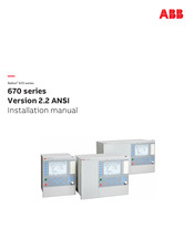
ABB Relion REC670 Installation Manual (102 pages)
Version 2.2 ANSI
Brand:
ABB
| Category:
Protection Device
| Size: 6.22 MB
Table of Contents
Table of Contents
7
Introduction
11
This Manual
11
Intended Audience
11
Section 1 Introduction
11
Product Documentation
12
Product Documentation Set
12
Document Revision History
13
Related Documents
13
Document Symbols and Conventions
15
Symbols
15
Document Conventions
16
Safety Information
17
Symbols on the Product
17
Warnings
17
Section 2 Safety Information
17
Caution Signs
18
Note Signs
19
Environmental Aspects
21
Sustainable Development
21
Disposing of the IED
21
Section 3 Environmental Aspects
21
Unpacking, Inspecting and Storing
23
Removing Transport Packaging
23
Inspecting the Product
23
Identifying the Product
23
Checking Delivery Items
23
Inspecting the IED
23
Returning an IED Damaged in Transit
23
Storing
24
Mounting
25
Required Tools
25
Checking Environmental Conditions and Mounting Space
25
Mounting the IED
25
Section 5 Mounting
25
Flush Mounting
26
Overview
26
Mounting Procedure for Flush Mounting
27
19" Panel Rack Mounting
27
Overview
27
Mounting Procedure for 19" Panel Rack Mounting
28
Wall Mounting
29
Overview
29
Mounting Procedure for Wall Mounting
29
How to Reach the Rear Side of the IED
29
Side-By-Side 19" Rack Mounting
30
Overview
30
Mounting Procedure for Side-By-Side Rack Mounting
31
IED Mounted with a RHGS6 Case
31
Side-By-Side Flush Mounting
32
Overview
32
Mounting Procedure for Side-By-Side Flush Mounting
33
Mounting the Injection Unit REX060 (REG670 Only)
33
Mounting the Coupling Capacitor Unit REX061 and Shunt Resistor Unit REX062 (REG670 Only)
34
Coupling Capacitor Unit REX061
34
Shunt Resistor Unit REX062
35
ABB Relion REC670 Product Manual (158 pages)
Bay control
Brand:
ABB
| Category:
Controller
| Size: 3.92 MB
Table of Contents
Table of Contents
2
Document Revision History
3
Application
4
Available Functions
10
Differential Protection
10
Unbalance Protection
12
Frequency Protection
12
Multipurpose Protection
12
General Calculation
12
Secondary System Supervision
14
Scheme Communication
38
Logic
39
Monitoring
41
Metering
45
Human Machine Interface
46
Basic IED Functions
46
Ethernet
46
Station Communication
47
Remote Communication
49
Hardware Description
50
Connection Diagrams
53
Certification
53
Technical Data
54
Ordering for Customized IED
134
Ordering for Pre-Configured IED
145
Ordering for Accessories
152
ABB Relion REC670 Product Manual (125 pages)
Brand:
ABB
| Category:
Control Systems
| Size: 2.77 MB
Table of Contents
Table of Contents
2
Application
3
Available Functions
9
Control
9
Differential Protection
9
Current Protection
10
Voltage Protection
10
Frequency Protection
10
Multipurpose Protection
11
Secondary System Supervision
13
Logic
13
Monitoring
14
Metering
14
Basic IED Functions
19
Station Communication
34
Remote Communication
35
Hardware Description
35
Connection Diagrams
38
Technical Data
39
Ordering for Customized IED
104
Ordering for Pre-Configured IED
114
Ordering for Accessories
119
ABB Relion REC670 Communication Protocol Manual (48 pages)
Brand:
ABB
| Category:
Power distribution unit
| Size: 1.4 MB
Table of Contents
Table of Contents
7
Introduction
9
This Manual
9
Intended Audience
9
Product Documentation
9
Product Documentation Set
9
Document Revision History
10
Related Documents
11
Document Symbols and Conventions
12
Symbols
12
Document Conventions
13
SPA Application
15
SPA Communication Protocol
15
Application
15
Setting Guidelines
16
SPA Operation Principle
17
Operation Principle
17
Introduction of SPA Protocol
17
SPA Protocol
17
I/O Modules
18
Single Command, 16 Signals
18
Event Function EVENT
20
Connection of Signals as Events
21
Communication Ports
22
Design
22
SPA Settings
25
Settings
25
SPA Technical Data
27
Technical Data
27
Establishing Connection and Verifying the SPA/IEC Communication
29
Entering Settings
29
Entering SPA Settings
29
Verifying the Communication
29
Verifying SPA Communication
29
Fiber Optic Loop
30
Optical Budget Calculation for Serial Communication with SPA/IEC
30
SPA Functions
31
SPA, 670 Series Communication Protocol Manual
31
Event Function EVENT
31
Identification
31
Function Block
31
Signals
31
Settings
32
Operation Principle
34
Setting Guidelines
35
Eventmask (Ch_1 - 16)
35
Lonchannelmask or Spachannelmask
35
Minrepintval (1 - 16)
36
Logical Signal Status Report BINSTATREP
36
Identification
36
ABB Relion REC670 Product Manual (89 pages)
Relion 670 series, Pre-configured
Brand:
ABB
| Category:
Power protection unit
| Size: 2.59 MB
Table of Contents
Table of Contents
2
Application
3
Available Functions
4
Functionality
6
Hardware Description
19
Connection Diagrams
22
Technical Data
35
Ordering
78
Advertisement
Related Products
ABB RELION REL670
ABB REB650
ABB RET615 F
ABB RET615 K
ABB REM615 C
ABB REF615 E
ABB REF615 A
ABB REJ 513
ABB RE 610 Series
ABB RET615 C
ABB Categories
Industrial Equipment
Controller
Measuring Instruments
Battery Charger
DC Drives
More ABB Manuals
Login
Sign In
OR
Sign in with Facebook
Sign in with Google
Upload manual
Upload from disk
Upload from URL