ABB Relion REC670 Applications Manual
Bay control version 2.1 iec
Hide thumbs
Also See for Relion REC670:
- Applications manual (658 pages) ,
- Commissioning manual (218 pages) ,
- Product manual (139 pages)
Table of Contents
Advertisement
Quick Links
Advertisement
Table of Contents

Subscribe to Our Youtube Channel
Related Manuals for ABB Relion REC670


Summary of Contents for ABB Relion REC670
- Page 1 — R E L I O N ® 670 SERIES Bay control REC670 Version 2.1 IEC Application manual...
- Page 3 Document ID: 1MRK 511 358-UEN Issued: March 2019 Revision: A Product version: 2.1 © Copyright 2016 ABB. All rights reserved...
- Page 4 Copyright This document and parts thereof must not be reproduced or copied without written permission from ABB, and the contents thereof must not be imparted to a third party, nor used for any unauthorized purpose. The software and hardware described in this document is furnished under a license and may be used or disclosed only in accordance with the terms of such license.
- Page 5 This document has been carefully checked by ABB but deviations cannot be completely ruled out. In case any errors are detected, the reader is kindly requested to notify the manufacturer.
- Page 6 (Low-voltage directive 2006/95/EC). This conformity is the result of tests conducted by ABB in accordance with the product standard EN 60255-26 for the EMC directive, and with the product standards EN 60255-1 and EN 60255-27 for the low voltage directive. The...
-
Page 7: Table Of Contents
Table of contents Table of contents Section 1 Introduction.......................17 This manual............................17 Intended audience..........................17 Product documentation........................18 1.3.1 Product documentation set...................... 18 1.3.2 Document revision history......................19 1.3.3 Related documents........................19 Document symbols and conventions..................20 1.4.1 Symbols............................20 1.4.2 Document conventions.......................21 IEC61850 edition 1 / edition 2 mapping..................21 Section 2 Application...................... - Page 8 Table of contents 4.2.2.7 Example how to connect single-phase CT to the IED............64 4.2.3 Relationships between setting parameter Base Current, CT rated primary current and minimum pickup of a protection IED..............65 4.2.4 Setting of voltage channels.......................66 4.2.4.1 Example............................66 4.2.4.2 Examples how to connect, configure and set VT inputs for most commonly used VT connections.......................
- Page 9 Table of contents 7.2.2 Application..........................105 7.2.3 Setting guidelines........................106 7.2.3.1 Settings for each step......................107 7.2.3.2 2nd harmonic restrain......................110 Instantaneous residual overcurrent protection EFPIOC ............114 7.3.1 Identification..........................115 7.3.2 Application..........................115 7.3.3 Setting guidelines........................115 Four step residual overcurrent protection, (Zero sequence or negative sequence directionality) EF4PTOC .......................
- Page 10 Table of contents 7.11 Pole discordance protection CCPDSC..................151 7.11.1 Identification..........................152 7.11.2 Application..........................152 7.11.3 Setting guidelines........................152 7.12 Directional underpower protection GUPPDUP................ 153 7.12.1 Identification..........................153 7.12.2 Application..........................153 7.12.3 Setting guidelines........................155 7.13 Directional overpower protection GOPPDOP ................158 7.13.1 Identification..........................158 7.13.2 Application..........................
- Page 11 Table of contents 8.2.2 Application..........................178 8.2.3 Setting guidelines........................179 8.2.3.1 Equipment protection, such as for motors, generators, reactors and transformers........................... 179 8.2.3.2 Equipment protection, capacitors..................179 8.2.3.3 Power supply quality......................179 8.2.3.4 High impedance earthed systems..................180 8.2.3.5 The following settings can be done for the two step overvoltage protection..180 Two step residual overvoltage protection ROV2PTOV ............
- Page 12 Table of contents Section 10 Multipurpose protection................199 10.1 General current and voltage protection CVGAPC..............199 10.1.1 Identification..........................199 10.1.2 Application..........................199 10.1.2.1 Current and voltage selection for CVGAPC function............200 10.1.2.2 Base quantities for CVGAPC function................202 10.1.2.3 Application possibilities....................... 202 10.1.2.4 Inadvertent generator energization...................203 10.1.3 Setting guidelines........................
- Page 13 Table of contents 13.1.1 Identification..........................225 13.1.2 Application..........................225 13.1.2.1 Synchronizing..........................225 13.1.2.2 Synchrocheck.......................... 226 13.1.2.3 Energizing check........................228 13.1.2.4 Voltage selection........................228 13.1.2.5 External fuse failure.......................229 13.1.3 Application examples....................... 230 13.1.3.1 Single circuit breaker with single busbar................230 13.1.3.2 Single circuit breaker with double busbar, external voltage selection......231 13.1.3.3 Single circuit breaker with double busbar, internal voltage selection......
- Page 14 Table of contents 13.3.1.3 Switches (SXCBR/SXSWI)..................... 261 13.3.1.4 Reservation function (QCRSV and RESIN)................. 261 13.3.2 Interaction between modules....................263 13.3.3 Setting guidelines........................264 13.3.3.1 Bay control (QCBAY)......................264 13.3.3.2 Switch controller (SCSWI).....................265 13.3.3.3 Switch (SXCBR/SXSWI)......................266 13.3.3.4 Bay Reserve (QCRSV)......................266 13.3.3.5 Reservation input (RESIN)....................266 13.4 Interlocking ............................
- Page 15 Table of contents 13.5 Voltage control..........................297 13.5.1 Identification..........................297 13.5.2 Application..........................297 13.5.3 Setting guidelines........................324 13.5.3.1 TR1ATCC or TR8ATCC general settings................324 13.5.3.2 TR1ATCC or TR8ATCC Setting group ................325 13.5.3.3 TCMYLTC and TCLYLTC general settings................. 332 13.6 Logic rotating switch for function selection and LHMI presentation SLGAPC....332 13.6.1 Identification..........................
- Page 16 Table of contents 14.1.3.6 Intertrip scheme........................347 14.2 Current reversal and Weak-end infeed logic for distance protection 3-phase ZCRWPSCH ............................. 347 14.2.1 Identification..........................347 14.2.2 Application..........................348 14.2.2.1 Current reversal logic......................348 14.2.2.2 Weak-end infeed logic......................348 14.2.3 Setting guidelines........................349 14.2.3.1 Current reversal logic......................
- Page 17 Table of contents 15.4.1 Logic for group warning WRNCALH..................362 15.4.1.1 Identification...........................362 15.4.1.2 Application..........................362 15.4.1.3 Setting guidelines........................362 15.5 Logic for group indication INDCALH..................362 15.5.1 Logic for group indication INDCALH..................362 15.5.1.1 Identification...........................362 15.5.1.2 Application..........................362 15.5.1.3 Setting guidelines........................363 15.6 Configurable logic blocks......................363 15.6.1...
- Page 18 Table of contents 16.1.3 Zero clamping..........................376 16.1.4 Setting guidelines........................377 16.1.4.1 Setting examples........................379 16.2 Gas medium supervision SSIMG....................385 16.2.1 Identification..........................385 16.2.2 Application..........................385 16.3 Liquid medium supervision SSIML..................... 385 16.3.1 Identification..........................385 16.3.2 Application..........................386 16.4 Breaker monitoring SSCBR......................386 16.4.1 Identification..........................386 16.4.2 Application..........................386 16.4.3...
- Page 19 Table of contents 17.1 Pulse-counter logic PCFCNT......................401 17.1.1 Identification..........................401 17.1.2 Application..........................401 17.1.3 Setting guidelines........................401 17.2 Function for energy calculation and demand handling ETPMMTR........402 17.2.1 Identification..........................402 17.2.2 Application..........................402 17.2.3 Setting guidelines........................403 Section 18 Station communication.................405 18.1 Communication protocols......................405 18.2 IEC 61850-8-1 communication protocol...................
- Page 20 Table of contents 19.1.1 Identification..........................431 19.1.2 Application..........................431 19.1.2.1 Communication hardware solutions..................431 19.1.3 Setting guidelines........................432 Section 20 Security......................437 20.1 Authority status ATHSTAT......................437 20.1.1 Application..........................437 20.2 Self supervision with internal event list INTERRSIG..............437 20.2.1 Application..........................437 20.3 Change lock CHNGLCK......................... 438 20.3.1 Application..........................
- Page 21 Table of contents 21.10.1 Application..........................446 21.10.2 Setting guidelines........................446 21.11 Signal matrix for analog inputs SMAI..................446 21.11.1 Application..........................446 21.11.2 Frequency values........................446 21.11.3 Setting guidelines........................447 21.12 Test mode functionality TEST..................... 451 21.12.1 Application..........................451 21.12.1.1 IEC 61850 protocol test mode.....................452 21.12.2 Setting guidelines........................
-
Page 23: Introduction
1MRK 511 358-UEN A Section 1 Introduction Section 1 Introduction This manual GUID-AB423A30-13C2-46AF-B7FE-A73BB425EB5F v19 The application manual contains application descriptions and setting guidelines sorted per function. The manual can be used to find out when and for what purpose a typical protection function can be used. -
Page 24: Product Documentation
Section 1 1MRK 511 358-UEN A Introduction Product documentation 1.3.1 Product documentation set GUID-3AA69EA6-F1D8-47C6-A8E6-562F29C67172 v15 Engineering manual Installation manual Commissioning manual Operation manual Application manual Technical manual Communication protocol manual Cyber security deployment guideline IEC07000220-4-en.vsd IEC07000220 V4 EN-US Figure 1: The intended use of manuals throughout the product lifecycle The engineering manual contains instructions on how to engineer the IEDs using the various tools available within the PCM600 software. -
Page 25: Document Revision History
1MRK 511 358-UEN A Section 1 Introduction The application manual contains application descriptions and setting guidelines sorted per function. The manual can be used to find out when and for what purpose a typical protection function can be used. The manual can also provide assistance for calculating settings. The technical manual contains operation principle descriptions, and lists function blocks, logic diagrams, input and output signals, setting parameters and technical data, sorted per function. -
Page 26: Document Symbols And Conventions
Section 1 1MRK 511 358-UEN A Introduction 670 series manuals Document numbers Cyber security deployment guideline 1MRK 511 356-UEN Connection and Installation components 1MRK 513 003-BEN Test system, COMBITEST 1MRK 512 001-BEN Document symbols and conventions 1.4.1 Symbols GUID-2945B229-DAB0-4F15-8A0E-B9CF0C2C7B15 v12 The electrical warning icon indicates the presence of a hazard which could result in electrical shock. -
Page 27: Document Conventions
1MRK 511 358-UEN A Section 1 Introduction 1.4.2 Document conventions GUID-96DFAB1A-98FE-4B26-8E90-F7CEB14B1AB6 v8 • Abbreviations and acronyms in this manual are spelled out in the glossary. The glossary also contains definitions of important terms. • Push button navigation in the LHMI menu structure is presented by using the push button icons. - Page 28 Section 1 1MRK 511 358-UEN A Introduction Function block name Edition 1 logical nodes Edition 2 logical nodes BUSPTRC_B8 BUSPTRC BUSPTRC BUSPTRC_B9 BUSPTRC BUSPTRC BUSPTRC_B10 BUSPTRC BUSPTRC BUSPTRC_B11 BUSPTRC BUSPTRC BUSPTRC_B12 BUSPTRC BUSPTRC BUSPTRC_B13 BUSPTRC BUSPTRC BUSPTRC_B14 BUSPTRC BUSPTRC BUSPTRC_B15 BUSPTRC BUSPTRC BUSPTRC_B16...
- Page 29 1MRK 511 358-UEN A Section 1 Introduction Function block name Edition 1 logical nodes Edition 2 logical nodes CBPGAPC CBPLLN0 CBPMMXU CBPMMXU CBPPTRC CBPPTRC HOLPTOV HOLPTOV HPH1PTOV HPH1PTOV PH3PTOC PH3PTUC PH3PTUC PH3PTOC RP3PDOP RP3PDOP CCPDSC CCRPLD CCPDSC CCRBRF CCRBRF CCRBRF CCRWRBRF CCRWRBRF CCRWRBRF...
- Page 30 Section 1 1MRK 511 358-UEN A Introduction Function block name Edition 1 logical nodes Edition 2 logical nodes GENPDIF GENPDIF GENGAPC GENPDIF GENPHAR GENPTRC GOOSEBINRCV BINGREC GOOSEDPRCV DPGREC GOOSEINTLKRCV INTGREC GOOSEINTRCV INTSGREC GOOSEMVRCV MVGREC GOOSESPRCV BINSGREC GOOSEVCTRRCV VCTRGREC GOPPDOP GOPPDOP GOPPDOP PH1PTRC GRPTTR...
- Page 31 1MRK 511 358-UEN A Section 1 Introduction Function block name Edition 1 logical nodes Edition 2 logical nodes LPHD LPHD LPTTR LPTTR LPTTR LT3CPDIF LT3CPDIF LT3CGAPC LT3CPDIF LT3CPHAR LT3CPTRC LT6CPDIF LT6CPDIF LT6CGAPC LT6CPDIF LT6CPHAR LT6CPTRC MVGAPC MVGGIO MVGAPC NS2PTOC NS2LLN0 NS2PTOC NS2PTOC NS2PTRC...
- Page 32 Section 1 1MRK 511 358-UEN A Introduction Function block name Edition 1 logical nodes Edition 2 logical nodes SAPTOF SAPTOF SAPTOF SAPTUF SAPTUF SAPTUF SCCVPTOC SCCVPTOC SCCVPTOC SCILO SCILO SCILO SCSWI SCSWI SCSWI SDEPSDE SDEPSDE SDEPSDE SDEPTOC SDEPTOV SDEPTRC SESRSYN RSY1LLN0 AUT1RSYN AUT1RSYN...
- Page 33 1MRK 511 358-UEN A Section 1 Introduction Function block name Edition 1 logical nodes Edition 2 logical nodes U2RWPTUV GEN2LLN0 PH1PTRC PH1PTRC U2RWPTUV U2RWPTUV UV2PTUV GEN2LLN0 PH1PTRC PH1PTRC UV2PTUV UV2PTUV VDCPTOV VDCPTOV VDCPTOV VDSPVC VDRFUF VDSPVC VMMXU VMMXU VMMXU VMSQI VMSQI VMSQI VNMMXU...
-
Page 35: Application
1MRK 511 358-UEN A Section 2 Application Section 2 Application General IED application M13637-3 v12 The IED is used for the control, protection and monitoring of different types of bays in power networks. The IED is especially suitable for applications in control systems where the IEC 61850–8–1 Ed 1 or Ed 2 station bus features of the IED can be fully utilized. -
Page 36: Main Protection Functions
Section 2 1MRK 511 358-UEN A Application Forcing of binary inputs and outputs is a convenient way to test wiring in substations as well as testing configuration logic in the IEDs. Basically it means that all binary inputs and outputs on the IED I/O modules (BOM, BIM, IOM &... - Page 37 1MRK 511 358-UEN A Section 2 Application IEC 61850 ANSI Function description Bay control REC670 (Customized) NS4PTOC 46I2 Four step 1-C51 1-C51 2-C52 2-C53 directional negative phase sequence overcurrent protection SDEPSDE Sensitive directional 1-C16 1–C16 1-C16 1-C16 residual overcurrent and power protection LCPTTR Thermal overload...
-
Page 38: Control And Monitoring Functions
Section 2 1MRK 511 358-UEN A Application IEC 61850 ANSI Function description Bay control REC670 (Customized) Frequency protection SAPTUF Underfrequency 6-E01 6-E01 6-E01 6-E01 protection SAPTOF Overfrequency 6-E01 6-E01 6-E01 6-E01 protection SAPFRC Rate-of-change 6-E01 6-E01 6-E01 6-E01 frequency protection FTAQFVR Frequency time 0-12... - Page 39 1MRK 511 358-UEN A Section 2 Application IEC 61850 ANSI Function description Bay control REC670 QCBAY Apparatus control 1+5/APC30 1+5/ APC3 LOCREM Handling of LRswitch 1+5/APC30 1+5/ positions APC3 LOCREMCTRL LHMI control of PSTO 1+5/APC30 1+5/ APC3 TR1ATCC Automatic voltage 1-H11 1-H11 1-H11...
- Page 40 Section 2 1MRK 511 358-UEN A Application IEC 61850 ANSI Function description Bay control REC670 Secondary system supervision CCSSPVC Current circuit supervision FUFSPVC Fuse failure supervision VDSPVC Fuse failure supervision 1-G03 1-G03 1-G03 1-G03 based on voltage difference Logic SMPPTRC Tripping logic TMAGAPC Trip matrix logic...
- Page 41 1MRK 511 358-UEN A Section 2 Application IEC 61850 ANSI Function description Bay control REC670 TEIGAPC Elapsed time integrator with limit transgression and overflow supervision INTCOMP Comparator for integer inputs REALCOMP Comparator for real inputs Monitoring CVMMXN, Measurements VMMXU, CMSQI, VMSQI, VNMMXU CMMXU Measurements...
- Page 42 Section 2 1MRK 511 358-UEN A Application IEC 61850 ANSI Function description Bay control REC670 I103EF Function status earth- fault for IEC 60870-5-103 I103FLTPROT Function status fault protection for IEC 60870-5-103 I103IED IED status for IEC 60870-5-103 I103SUPERV Supervison status for IEC 60870-5-103 I103USRDEF Status for user defined...
-
Page 43: Communication
1MRK 511 358-UEN A Section 2 Application Configurable logic blocks Q/T Total number of instances ORQT PULSETIMERQT RSMEMORYQT SRMEMORYQT TIMERSETQT XORQT Table 5: Total number of instances for extended logic package Extended configurable logic block Total number of instances GATE PULSETIMER SLGAPC SRMEMORY... - Page 44 Section 2 1MRK 511 358-UEN A Application IEC 61850 ANSI Function description Bay control REC670 (Customized) DNPGENTCP DNP3.0 communication general TCP protocol CHSERRS485 DNP3.0 for EIA-485 communication protocol CH1TCP, CH2TCP, DNP3.0 for TCP/IP CH3TCP, CH4TCP communication protocol CHSEROPT DNP3.0 for TCP/IP and EIA-485 communication protocol...
- Page 45 1MRK 511 358-UEN A Section 2 Application IEC 61850 ANSI Function description Bay control REC670 (Customized) OPTICAL103 IEC 60870-5-103 Optical serial communication RS485103 IEC 60870-5-103 serial communication for RS485 AGSAL Generic security application component LD0LLN0 IEC 61850 LD0 LLN0 SYSLLN0 IEC 61850 SYS LLN0 LPHD Physical device...
-
Page 46: Basic Ied Functions
Section 2 1MRK 511 358-UEN A Application IEC 61850 ANSI Function description Bay control REC670 (Customized) ZCRWPSCH Current reversal and 1-K01 1-K01 1-K01 1-K01 weak-end infeed logic for distance protection ZCLCPSCH Local acceleration logic 1-K01 1-K01 1-K01 1-K01 ECPSCH Scheme 1-C51 1-C51 1-C52... - Page 47 1MRK 511 358-UEN A Section 2 Application IEC 61850 or function Description name AUTHMAN Authority management FTPACCS FTP access with password SPACOMMMAP SPA communication mapping SPATD Date and time via SPA protocol DOSFRNT Denial of service, frame rate control for front port DOSLANAB Denial of service, frame rate control for OEM port AB DOSLANCD...
-
Page 49: Configuration
Configuration Introduction SEMOD120082-1 v1 SEMOD120089-4 v8 On request, ABB is available to support the re-configuration work, either directly or to do the design checking. Hardware modules are configured with the hardware configuration tool in the PCM600 engineering platform. The IED is available to be ordered in three different alternatives with the configuration suitable for the application. -
Page 50: Description Of Configuration Rec670
Section 3 1MRK 511 358-UEN A Configuration Optional functions and optional IO ordered will not be configured at delivery. It should be noted that the standard only includes one binary input and one binary output module and only the key functions such as tripping are connected to the outputs. The required total IO must be calculated and specified at ordering. -
Page 51: Description Of Configuration A31
1MRK 511 358-UEN A Section 3 Configuration REC670 A30 – Double busbar in single breaker arrangement 12AI (6I + 6U) Control Control Control S CILO S CSWI S XSWI Control Control Control S CILO S CSWI S XSWI WA2_VT VN MMXU WA1_VT Control Control... -
Page 52: Description Of Configuration B30
Section 3 1MRK 511 358-UEN A Configuration with full control of all apparatuses included, more IO cards are required. Our proposal for a full version with control is to use two binary input modules and one binary output module. REC670 A31 – Bus Coupler Bay arrangement 12AI (6I + 6U) Control Control Control... -
Page 53: Description Of Configuration C30
1MRK 511 358-UEN A Section 3 Configuration version with control is to use two binary input modules and one or two binary output modules. For systems without Substation Automation a second binary output board might be required. REC670 B30 - Double breaker arrangement 12AI (6I + 6U) Control Control Control... - Page 54 Section 3 1MRK 511 358-UEN A Configuration Control, measuring and interlocking is fully configured, including communication with other bays such as other lines and the bus coupler over GOOSE. The following should be noted. The configuration is made with the binary input and binary output boards in the basic IED delivery.
- Page 55 1MRK 511 358-UEN A Section 3 Configuration SEMOD51278-4 v10 Four packages have been defined for following applications: • Single breaker (double or single bus) arrangement (A30) • Bus coupler for double busbar (A31) • Double breaker arrangement (B30) • 1 ½ breaker arrangement for a complete diameter (C30) Optional functions are available in PCM600 Application Configuration Tool and can be configured by the user.
-
Page 57: Analog Inputs
1MRK 511 358-UEN A Section 4 Analog inputs Section 4 Analog inputs Introduction SEMOD55003-5 v10 Analog input channels must be configured and set properly in order to get correct measurement results and correct protection operations. For power measuring and all directional and differential functions the directions of the input currents must be defined in order to reflect the way the current transformers are installed/connected in the field ( primary and secondary connections ). -
Page 58: Example
Section 4 1MRK 511 358-UEN A Analog inputs 4.2.1.1 Example SEMOD55055-11 v4 Usually the L1 phase-to-earth voltage connected to the first VT channel number of the transformer input module (TRM) is selected as the phase reference. The first VT channel number depends on the type of transformer input module. -
Page 59: Example 2
1MRK 511 358-UEN A Section 4 Analog inputs Line Transformer Line Reverse Forward Definition of direction for directional functions Transformer protection Line protection Setting of current input: Setting of current input: Setting of current input: Set parameter Set parameter Set parameter CTStarPoint with CTStarPoint with CTStarPoint with... -
Page 60: Example 3
Section 4 1MRK 511 358-UEN A Analog inputs Transformer Line Reverse Forward Definition of direction for directional functions Transformer protection Line protection Setting of current input: Setting of current input: Setting of current input: Set parameter Set parameter Set parameter CTStarPoint with CTStarPoint with CTStarPoint with... - Page 61 1MRK 511 358-UEN A Section 4 Analog inputs Transformer Line Forward Reverse Definition of direction for directional Transformer and line functions Line protection Setting of current input: Setting of current input: Set parameter Set parameter CTStarPoint with CTStarPoint with Transformer as Transformer as reference object.
- Page 62 Section 4 1MRK 511 358-UEN A Analog inputs Transformer Line Reverse Forward Definition of direction for directional Transformer and line functions Line protection Setting of current input for line functions: Set parameter CTStarPoint with Line as reference object. Setting of current input Setting of current input Correct setting is for transformer functions:...
- Page 63 1MRK 511 358-UEN A Section 4 Analog inputs Busbar Busbar Protection en06000196.vsd IEC06000196 V2 EN-US Figure 11: Example how to set CTStarPoint parameters in the IED CTStarPoint parameters in two ways. For busbar protection it is possible to set the The first solution will be to use busbar as a reference object.
-
Page 64: Examples On How To Connect, Configure And Set Ct Inputs For Most Commonly Used Ct Connections
Section 4 1MRK 511 358-UEN A Analog inputs 4.2.2.4 Examples on how to connect, configure and set CT inputs for most commonly used CT connections SEMOD55055-296 v5 Figure defines the marking of current transformer terminals commonly used around the world: In the SMAI function block, you have to set if the SMAI block is measuring AnalogInputType : Current/ current or voltage. -
Page 65: Example On How To Connect A Star Connected Three-Phase Ct Set To The Ied
1MRK 511 358-UEN A Section 4 Analog inputs 4.2.2.5 Example on how to connect a star connected three-phase CT set to the SEMOD55055-352 v9 Figure gives an example about the wiring of a star connected three-phase CT set to the IED. It gives also an overview of the actions which are needed to make this measurement available to the built-in protection and control functions within the IED as well. - Page 66 Section 4 1MRK 511 358-UEN A Analog inputs These three connections are the links between the three current inputs and the three input channels of the preprocessing function block 4). Depending on the type of functions, which need this current information, more than one preprocessing block might be connected in parallel to the same three physical CT inputs.
- Page 67 1MRK 511 358-UEN A Section 4 Analog inputs In the example in figure 14 case everything is done in a similar way as in the above described example (figure 13). The only difference is the setting of the parameter CTStarPoint of the used current inputs on the TRM (item 2 in the figure): CTprim =600A •...
-
Page 68: Example How To Connect Delta Connected Three-Phase Ct Set To The Ied
Section 4 1MRK 511 358-UEN A Analog inputs is the TRM where these current inputs are located. It shall be noted that for all these current inputs the following setting values shall be entered. • CTprim=800A • CTsec=1A • CTStarPoint=FromObject •... - Page 69 1MRK 511 358-UEN A Section 4 Analog inputs IL1-IL2 SMAI2 BLOCK AI3P IL2-IL3 REVROT ^GRP2L1 IL3-IL1 ^GRP2L2 ^GRP2L3 ^GRP2N IEC11000027-3-en.vsdx Protected Object IEC11000027 V3 EN-US Figure 16: Delta DAB connected three-phase CT set Where: shows how to connect three individual phase currents from a delta connected three-phase CT set to three CT inputs of the IED.
-
Page 70: Example How To Connect Single-Phase Ct To The Ied
Section 4 1MRK 511 358-UEN A Analog inputs Another alternative is to have the delta connected CT set as shown in figure 17: IL1-IL3 SMAI2 BLOCK AI3P REVROT IL2-IL1 ^GRP2L1 ^GRP2L2 IL3-IL2 ^GRP2L3 ^GRP2N IEC11000028-3-en.vsdx Protected Object IEC11000028 V3 EN-US Figure 17: Delta DAC connected three-phase CT set In this case, everything is done in a similar way as in the above described example, except that... -
Page 71: Relationships Between Setting Parameter Base Current, Ct Rated Primary Current And Minimum Pickup Of A Protection Ied
1MRK 511 358-UEN A Section 4 Analog inputs Protected Object SMAI2 BLOCK AI3P REVROT ^GRP2L1 ^GRP2L2 ^GRP2L3 ^GRP2N IEC11000029-4-en.vsdx IEC11000029 V4 EN-US Figure 18: Connections for single-phase CT input Where: shows how to connect single-phase CT input in the IED. is TRM where these current inputs are located. -
Page 72: Setting Of Voltage Channels
Section 4 1MRK 511 358-UEN A Analog inputs CTs involved in the protection scheme. The rated CT primary current value is set as parameter CTPrim under the IED TRM settings. For all other protection applications (e.g. generator, shunt reactor, shunt capacitor and IBase parameter equal to the rated transformer protection) it is typically desirable to set current of the protected object. -
Page 73: Examples On How To Connect A Three Phase-To-Earth Connected Vt To The Ied
1MRK 511 358-UEN A Section 4 Analog inputs (X1) (X1) (X1) (H1) (H1) (H1) (H2) (X2) (H2) (X2) (H2) (X2) en06000591.vsd IEC06000591 V1 EN-US Figure 19: Commonly used markings of VT terminals Where: is the symbol and terminal marking used in this document. Terminals marked with a square indicate the primary and secondary winding terminals with the same (positive) polarity is the equivalent symbol and terminal marking used by IEC (ANSI) standard for phase-to-earth connected VTs... - Page 74 Section 4 1MRK 511 358-UEN A Analog inputs SMAI2 BLOCK AI3P REVROT ^GRP2L1 ^GRP2L2 ^GRP2L3 ^GRP2N #Not used IEC06000599-4-en.vsdx IEC06000599 V4 EN-US Figure 20: A Three phase-to-earth connected VT Where: shows how to connect three secondary phase-to-earth voltages to three VT inputs on the IED is the TRM where these three voltage inputs are located.
-
Page 75: Example On How To Connect A Phase-To-Phase Connected Vt To The Ied
1MRK 511 358-UEN A Section 4 Analog inputs are three connections made in Signal Matrix Tool (SMT), which connect these three voltage inputs to first three input channels of the preprocessing function block 5). Depending on the type of functions which need this voltage information, more then one preprocessing block might be connected in parallel to these three VT inputs. - Page 76 Section 4 1MRK 511 358-UEN A Analog inputs 13.8 13.8 SMAI2 BLOCK AI3P REVROT ^GRP2L1 ^GRP2L2 ^GRP2L3 #Not Used ^GRP2N IEC06000600-5-en.vsdx IEC06000600 V5 EN-US Figure 21: A Two phase-to-phase connected VT Where: shows how to connect the secondary side of a phase-to-phase VT to the VT inputs on the IED is the TRM where these three voltage inputs are located.
-
Page 77: Example On How To Connect An Open Delta Vt To The Ied For High Impedance Earthed Or Unearthed Netwoeks
1MRK 511 358-UEN A Section 4 Analog inputs 4.2.4.5 Example on how to connect an open delta VT to the IED for high impedance earthed or unearthed netwoeks SEMOD55055-163 v8 Figure gives an example about the wiring of an open delta VT to the IED for high impedance earthed or unearthed power systems. -
Page 78: Example How To Connect The Open Delta Vt To The Ied For Low Impedance Earthed Or Solidly Earthed Power Systems
Section 4 1MRK 511 358-UEN A Analog inputs Where: shows how to connect the secondary side of the open delta VT to one VT input on the IED. +3U0 shall be connected to the IED is the TRM where this voltage input is located. It shall be noted that for this voltage input the following setting values shall be entered: ×... - Page 79 1MRK 511 358-UEN A Section 4 Analog inputs Ph Ph Ph E (Equation 7) EQUATION1926 V1 EN-US The primary rated voltage of such VT is always equal to UPh-E Therefore, three series connected VT secondary windings will give the secondary voltage equal only to one individual VT secondary winding rating.
-
Page 80: Example On How To Connect A Neutral Point Vt To The Ied
Section 4 1MRK 511 358-UEN A Analog inputs Where: shows how to connect the secondary side of open delta VT to one VT input in the IED. +3Uo shall be connected to the IED. is TRM where this voltage input is located. It shall be noted that for this voltage input the following setting values shall be entered: ×... - Page 81 1MRK 511 358-UEN A Section 4 Analog inputs In case of a solid earth fault in high impedance earthed or unearthed systems the primary value of Uo voltage will be equal to: (Equation 11) EQUATION1931 V2 EN-US Figure gives an overview of required actions by the user in order to make this measurement available to the built-in protection and control functions within the IED as well.
- Page 82 Section 4 1MRK 511 358-UEN A Analog inputs Where: shows how to connect the secondary side of neutral point VT to one VT input in the IED. shall be connected to the IED. is the TRM or AIM where this voltage input is located. For this voltage input the following setting values shall be entered: VTprim 3.81...
-
Page 83: Local Hmi
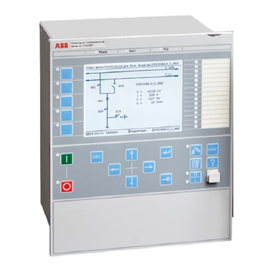
1MRK 511 358-UEN A Section 5 Local HMI Section 5 Local HMI AMU0600442 v14 IEC13000239-2-en.vsd IEC13000239 V2 EN-US Figure 25: Local human-machine interface The LHMI of the IED contains the following elements: • Keypad • Display (LCD) • LED indicators •... -
Page 84: Display
Section 5 1MRK 511 358-UEN A Local HMI Display GUID-55739D4F-1DA5-4112-B5C7-217AAF360EA5 v10 The LHMI includes a graphical monochrome liquid crystal display (LCD) with a resolution of 320 x 240 pixels. The character size can vary. The amount of characters and rows fitting the view depends on the character size and the view that is shown. -
Page 85: Leds
1MRK 511 358-UEN A Section 5 Local HMI IEC13000281-1-en.vsd GUID-C98D972D-D1D8-4734-B419-161DBC0DC97B V1 EN-US Figure 27: Function button panel The indication LED panel shows on request the alarm text labels for the indication LEDs. Three indication LED pages are available. IEC13000240-1-en.vsd GUID-5157100F-E8C0-4FAB-B979-FD4A971475E3 V1 EN-US Figure 28: Indication LED panel The function button and indication LED panels are not visible at the same time. -
Page 86: Keypad
Section 5 1MRK 511 358-UEN A Local HMI three LED groups. The LEDs are lit according to priority, with red being the highest and green the lowest priority. For example, if on one panel there is an indication that requires the green LED to be lit, and on another panel there is an indication that requires the red LED to be lit, the red LED takes priority and is lit. - Page 87 1MRK 511 358-UEN A Section 5 Local HMI IEC15000157-1-en.vsd IEC15000157 V1 EN-US Figure 29: LHMI keypad with object control, navigation and command push-buttons and RJ-45 communication port 1...5 Function button Close Open Escape Left Down Right Enter Remote/Local Uplink LED Not in use Multipage Menu...
-
Page 88: Local Hmi Functionality
Section 5 1MRK 511 358-UEN A Local HMI IED status LEDs Local HMI functionality 5.4.1 Protection and alarm indication GUID-09CCB9F1-9B27-4C12-B253-FBE95EA537F5 v15 Protection indicators The protection indicator LEDs are Ready, Start and Trip. The start and trip LEDs are configured via the disturbance recorder. The yellow and red status LEDs are configured in the disturbance recorder function, DRPRDRE, by connecting a start or trip signal from the actual function to a BxRBDR binary input function block using the PCM600 and configure the... -
Page 89: Parameter Management
1MRK 511 358-UEN A Section 5 Local HMI Alarm indicators The 15 programmable three-color LEDs are used for alarm indication. An individual alarm/ status signal, connected to any of the LED function blocks, can be assigned to one of the three LED colors when configuring the IED. - Page 90 Section 5 1MRK 511 358-UEN A Local HMI IEC13000280-1-en.vsd GUID-AACFC753-BFB9-47FE-9512-3C4180731A1B V1 EN-US Figure 30: RJ-45 communication port and green indicator LED 1 RJ-45 connector 2 Green indicator LED The default IP address for the IED front port is 10.1.150.3 and the corresponding subnetwork mask is 255.255.255.0.
-
Page 91: Differential Protection
1MRK 511 358-UEN A Section 6 Differential protection Section 6 Differential protection High impedance differential protection, single phase HZPDIF IP14239-1 v4 6.1.1 Identification M14813-1 v4 IEC 61850 IEC 60617 ANSI/IEEE C37.2 Function description identification identification device number High impedance differential HZPDIF protection, single phase SYMBOL-CC V2 EN-US... - Page 92 Section 6 1MRK 511 358-UEN A Differential protection 3·Id 3·Id 3·Id 3·Id 3·Id IEC05000163-4-en.vsd IEC05000163 V4 EN-US 3·Id Z< 3·Id Z< IEC05000738-3-en.vsd IEC05000738 V3 EN-US Application manual...
-
Page 93: The Basics Of The High Impedance Principle
1MRK 511 358-UEN A Section 6 Differential protection Figure 31: Different applications of a 1Ph High impedance differential protection HZPDIF function 6.1.2.1 The basics of the high impedance principle SEMOD54734-153 v9 The high impedance differential protection principle has been used for many years and is well documented in literature publicly available. - Page 94 Section 6 1MRK 511 358-UEN A Differential protection calculations are made with the worst situations in mind and a minimum operating voltage U is calculated according to equation > × Rct Rl (Equation 14) EQUATION1531 V1 EN-US where: IF max is the maximum through fault current at the secondary side of the CT is the current transformer secondary winding resistance and is the maximum loop resistance of the circuit at any CT.
- Page 95 1MRK 511 358-UEN A Section 6 Differential protection Table 12: 1 A channels: input with minimum operating down to 40 mA Operating Stabilizing Operating Stabilizing Operating voltage resistor R current level resistor R current level U>Trip ohms ohms 20 V 0.040 A 40 V 1000...
- Page 96 Section 6 1MRK 511 358-UEN A Differential protection in fault current to allow the use of only the AC components of the fault current in the above calculations. The voltage dependent resistor (Metrosil) characteristic is shown in Figure 38. Series resistor thermal capacity SEMOD54734-336 v6 U>Trip /SeriesResistor should...
- Page 97 1MRK 511 358-UEN A Section 6 Differential protection Rres I> Protected Object a) Through load situation b) Through fault situation c) Internal faults IEC05000427-2-en.vsd IEC05000427 V2 EN-US Figure 33: The high impedance principle for one phase with two current transformer inputs Application manual...
-
Page 98: Connection Examples For High Impedance Differential Protection
Section 6 1MRK 511 358-UEN A Differential protection 6.1.3 Connection examples for high impedance differential protection GUID-8C58A73D-7C2E-4BE5-AB87-B4C93FB7D62B v5 WARNING! USE EXTREME CAUTION! Dangerously high voltages might be present on this equipment, especially on the plate with resistors. De-energize the primary object protected with this equipment before connecting or disconnecting wiring or performing any maintenance. -
Page 99: Connections For 1Ph High Impedance Differential Protection Hzpdif
1MRK 511 358-UEN A Section 6 Differential protection Necessary connection for setting resistors. Factory-made star point on a three-phase setting resistor set. The star point connector must be removed for installations with 670 series IEDs. This star point is required for RADHA schemes only. Connections of three individual phase currents for high impedance scheme to three CT inputs in the IED. -
Page 100: Setting Guidelines
Section 6 1MRK 511 358-UEN A Differential protection 6.1.4 Setting guidelines IP14945-1 v1 M13076-3 v2 The setting calculations are individual for each application. Refer to the different application descriptions below. 6.1.4.1 Configuration M13076-5 v4 The configuration is done in the Application Configuration tool. 6.1.4.2 Settings of protection function M13076-10 v6... - Page 101 1MRK 511 358-UEN A Section 6 Differential protection 3·Id IEC05000165-2-en.vsd IEC05000165 V2 EN-US 3·Id IEC05000739-2-en.vsd IEC05000739 V2 EN-US Figure 36: The protection scheme utilizing the high impedance function for the T-feeder Normally this scheme is set to achieve a sensitivity of around 20 percent of the used CT primary rating so that a low ohmic value can be used for the series resistor.
- Page 102 Section 6 1MRK 511 358-UEN A Differential protection It is strongly recommended to use the highest tap of the CT whenever high impedance protection is used. This helps in utilizing maximum CT capability, minimize the secondary fault current, thereby reducing the stability voltage limit.
-
Page 103: Tertiary Reactor Protection
1MRK 511 358-UEN A Section 6 Differential protection The magnetizing current is taken from the magnetizing curve for the current transformer cores which should be available. The current value at U>Trip is taken. For the voltage dependent resistor current the peak value of voltage 200 ˣ √2 is used. Then the RMS current is calculated by dividing obtained current value from the metrosil curve with√2. - Page 104 Section 6 1MRK 511 358-UEN A Differential protection Setting example It is strongly recommended to use the highest tap of the CT whenever high impedance protection is used. This helps in utilizing maximum CT capability, minimize the secondary fault, thereby reducing the stability voltage limit. Another factor is that during internal faults, the voltage developed across the selected tap is limited by the non-linear resistor but in the unused taps, owing to auto-transformer action, voltages much higher than design limits might be...
-
Page 105: Alarm Level Operation
1MRK 511 358-UEN A Section 6 Differential protection dividing obtained current value from the metrosil curve with √2. Use the maximum value from the metrosil curve given in Figure 38. 6.1.4.5 Alarm level operation M16850-196 v6 The 1Ph High impedance differential protection HZPDIF function has a separate alarm level, which can be used to give alarm for problems with an involved current transformer circuit. -
Page 107: Current Protection
1MRK 511 358-UEN A Section 7 Current protection Section 7 Current protection Instantaneous phase overcurrent protection PHPIOC IP14506-1 v6 7.1.1 Identification M14880-1 v4 Function description IEC 61850 IEC 60617 ANSI/IEEE C37.2 identification identification device number Instantaneous phase overcurrent PHPIOC protection 3-phase output 3I>>... -
Page 108: Meshed Network Without Parallel Line
Section 7 1MRK 511 358-UEN A Current protection Only detailed network studies can determine the operating conditions under which the highest possible fault current is expected on the line. In most cases, this current appears during three-phase fault conditions. But also examine single-phase-to-earth and two-phase- to-earth conditions. - Page 109 1MRK 511 358-UEN A Section 7 Current protection Fault IEC09000023-1-en.vsd IEC09000023 V1 EN-US Figure 40: Through fault current from B to A: I The IED must not trip for any of the two through-fault currents. Hence the minimum theoretical current setting (Imin) will be: ³...
-
Page 110: Meshed Network With Parallel Line
Section 7 1MRK 511 358-UEN A Current protection 7.1.3.2 Meshed network with parallel line M12915-34 v6 In case of parallel lines, the influence of the induced current from the parallel line to the protected line has to be considered. One example is given in figure where the two lines are connected to the same busbars. -
Page 111: Four Step Phase Overcurrent Protection Oc4Ptoc
1MRK 511 358-UEN A Section 7 Current protection Four step phase overcurrent protection OC4PTOC SEMOD129998-1 v7 7.2.1 Identification M14885-1 v5 Function description IEC 61850 IEC 60617 ANSI/IEEE C37.2 identification identification device number Four step phase overcurrent OC4PTOC 51_67 protection 3-phase output TOC-REVA V2 EN-US 7.2.2 Application... -
Page 112: Setting Guidelines
Section 7 1MRK 511 358-UEN A Current protection to the current pick-up level. This multiplication factor is activated from a binary input signal to the function. Power transformers can have a large inrush current, when being energized. This phenomenon is due to saturation of the transformer magnetic core during parts of the period. There is a risk that inrush current will reach levels above the pick-up current of the phase overcurrent protection. -
Page 113: Settings For Each Step
1MRK 511 358-UEN A Section 7 Current protection IEC09000636_1_vsd IEC09000636 V1 EN-US Figure 43: Directional function characteristic RCA = Relay characteristic angle ROA = Relay operating angle Reverse Forward 7.2.3.1 Settings for each step M12982-19 v10.1.1 x means step 1, 2, 3 and 4. DirModex : The directional mode of step x . - Page 114 Section 7 1MRK 511 358-UEN A Current protection Curve name ANSI Moderately Inverse ANSI/IEEE Definite time ANSI Long Time Extremely Inverse ANSI Long Time Very Inverse ANSI Long Time Inverse IEC Normal Inverse IEC Very Inverse IEC Inverse IEC Extremely Inverse IEC Short Time Inverse IEC Long Time Inverse IEC Definite Time...
- Page 115 1MRK 511 358-UEN A Section 7 Current protection Operate time txMin IMinx Current IEC10000058 IEC10000058 V2 EN-US Figure 44: Minimum operate current and operate time for inverse time characteristics txMin shall be In order to fully comply with the definition of the curve, the setting parameter set to a value equal to the operating time of the selected inverse curve for twenty times the set current pickup value.
-
Page 116: 2Nd Harmonic Restrain
Section 7 1MRK 511 358-UEN A Current protection æ ö ç ÷ ç ÷ × IxMult ç ÷ æ ö ç ç ÷ ÷ è è ø ø > (Equation 28) EQUATION1261 V2 EN-US tPRCrvx , tTRCrvx , tCRCrvx : These parameters are used by the customer to create the inverse Technical manual . - Page 117 1MRK 511 358-UEN A Section 7 Current protection Current I Line phase current Operate current Reset current The IED does not reset Time t IEC05000203-en-2.vsd IEC05000203 V3 EN-US Figure 45: Operate and reset current for an overcurrent protection The lowest setting value can be written according to equation 29. Im ax ³...
- Page 118 Section 7 1MRK 511 358-UEN A Current protection £ × 0.7 Isc min (Equation 30) EQUATION1263 V2 EN-US where: is a safety factor Iscmin is the smallest fault current to be detected by the overcurrent protection. As a summary the operating current shall be chosen within the interval stated in equation 31. Im ax ×...
- Page 119 1MRK 511 358-UEN A Section 7 Current protection en05000204.wmf IEC05000204 V1 EN-US Figure 46: Fault time with maintained selectivity The operation time can be set individually for each overcurrent protection. To assure selectivity between different protections, in the radial network, there have to be a minimum time difference Dt between the time delays of two protections.
-
Page 120: Instantaneous Residual Overcurrent Protection Efpioc
Section 7 1MRK 511 358-UEN A Current protection Feeder I> I> Time axis The fault Protection Breaker at Protection occurs B1 trips B1 opens A1 resets en05000205.vsd IEC05000205 V1 EN-US Figure 47: Sequence of events during fault where: is when the fault occurs is when the trip signal from the overcurrent protection at IED B1 is sent to the circuit breaker. -
Page 121: Identification
1MRK 511 358-UEN A Section 7 Current protection 7.3.1 Identification M14887-1 v4 Function description IEC 61850 IEC 60617 ANSI/IEEE C37.2 identification identification device number Instantaneous residual overcurrent EFPIOC protection IN>> IEF V1 EN-US 7.3.2 Application M12699-3 v5 In many applications, when fault current is limited to a defined value by the object impedance, an instantaneous earth-fault protection can provide fast and selective tripping. - Page 122 Section 7 1MRK 511 358-UEN A Current protection Fault IEC09000023-1-en.vsd IEC09000023 V1 EN-US Figure 49: Through fault current from B to A: I The function shall not operate for any of the calculated currents to the protection. The minimum theoretical current setting (Imin) will be: ³...
-
Page 123: Four Step Residual Overcurrent Protection, (Zero Sequence Or Negative Sequence Directionality) Ef4Ptoc
1MRK 511 358-UEN A Section 7 Current protection ³ I m in M A X I (Equation 36) EQUATION287 V1 EN-US Where: and I have been described for the single line case. Considering the safety margins mentioned previously, the minimum setting (Is) is: = 1.3 ×... - Page 124 Section 7 1MRK 511 358-UEN A Current protection In many applications several steps with different current operating levels and time delays are needed. EF4PTOC can have up to four, individual settable steps. The flexibility of each step of EF4PTOC is great. The following options are possible: Non-directional/Directional function: In some applications the non-directional functionality is used.
-
Page 125: Setting Guidelines
1MRK 511 358-UEN A Section 7 Current protection to the residual current pick-up level. This multiplication factor is activated from a binary input signal ENMULTx to the function. Power transformers can have a large inrush current, when being energized. This inrush current can have residual current components. - Page 126 Section 7 1MRK 511 358-UEN A Current protection Protection operate time: 15-60 ms Protection resetting time: 15-60 ms Breaker opening time: 20-120 ms The different characteristics are described in the technical reference manual. tx : Definite time delay for step x . The definite time tx is added to the inverse time when inverse time characteristic is selected.
-
Page 127: Common Settings For All Steps
1MRK 511 358-UEN A Section 7 Current protection tResetx : Constant reset time delay in s for step x. HarmBlockx : This is used to enable block of step x from 2 harmonic restrain function. tPCrvx, tACrvx, tBCrvx, tCCrvx : Parameters for user programmable of inverse time characteristic curve. -
Page 128: 2Nd Harmonic Restrain
Section 7 1MRK 511 358-UEN A Current protection Voltage (3U • or U Current (3I • · ZNpol or 3I ·ZNpol where ZNpol is RNpol + jXNpol), or Dual (dual polarizing, (3U • both currents and voltage, + 3I · ZNpol) or (U ·... -
Page 129: Switch Onto Fault Logic
1MRK 511 358-UEN A Section 7 Current protection of the two transformers will be in phase opposition. The summation of the two currents will thus give a small 2 harmonic current. The residual fundamental current will however be significant. The inrush current of the transformer in service before the parallel transformer energizing, will be a little delayed compared to the first transformer. -
Page 130: Line Application Example
Section 7 1MRK 511 358-UEN A Current protection ActivationSOTF : This setting will select the signal to activate SOTF function; CB position open/CB position closed/CB close command . tSOTF : Time delay for operation of the SOTF function. The setting range is 0.000 - 60.000 s in step of 0.001 s. - Page 131 1MRK 511 358-UEN A Section 7 Current protection Step 1 M15282-123 v5 This step has directional instantaneous function. The requirement is that overreaching of the protected line is not allowed. One- or two-phase earth-fault or unsymmetric short circuit without earth connection IEC05000150-3-en.vsd IEC05000150 V4 EN-US Figure 55: Step 1, first calculation...
- Page 132 Section 7 1MRK 511 358-UEN A Current protection A higher value of step 1 might be necessary if a big power transformer (Y0/D) at remote bus bar is disconnected. A special case occurs at double circuit lines, with mutual zero-sequence impedance between the parallel lines, see figure 57.
- Page 133 1MRK 511 358-UEN A Section 7 Current protection The residual current, out on the line, is calculated at an operational case with minimal earth- fault current. The requirement that the whole line shall be covered by step 2 can be formulated according to equation 42.
-
Page 134: Four Step Directional Negative Phase Sequence Overcurrent Protection Ns4Ptoc
Section 7 1MRK 511 358-UEN A Current protection ³ × × step3 step2 (Equation 44) EQUATION1204 V4 EN-US where: is the chosen current setting for step 2 on the faulted line. step2 Step 4 M15282-177 v4 This step normally has non-directional function and a relatively long time delay. The task for step 4 is to detect and initiate trip for earth faults with large fault resistance, for example tree faults. - Page 135 1MRK 511 358-UEN A Section 7 Current protection In many applications several steps with different current operating levels and time delays are needed. NS4PTOC can have up to four, individual settable steps. The flexibility of each step of NS4PTOC function is great. The following options are possible: Non-directional/Directional function: In some applications the non-directional functionality is used.
-
Page 136: Setting Guidelines
Section 7 1MRK 511 358-UEN A Current protection 7.5.3 Setting guidelines GUID-460D6C58-598C-421E-AA9E-FD240210A6CC v3 The parameters for Four step negative sequence overcurrent protection NS4PTOC are set via the local HMI or Protection and Control Manager (PCM600). The following settings can be done for the four step negative sequence overcurrent protection: Operation : Sets the protection to On or Off . - Page 137 1MRK 511 358-UEN A Section 7 Current protection The different characteristics are described in the Technical Reference Manual (TRM). Ix> : Operation negative sequence current level for step x given in % of IBase . tx : Definite time delay for step x . The definite time tx is added to the inverse time when inverse time characteristic is selected.
-
Page 138: Common Settings For All Steps
Section 7 1MRK 511 358-UEN A Current protection For IEC inverse time delay characteristics the possible delay time settings are instantaneous (1) and IEC (2 = set constant time reset). For the programmable inverse time delay characteristics all three types of reset time characteristics are available;... -
Page 139: Sensitive Directional Residual Overcurrent And Power Protection Sdepsde
1MRK 511 358-UEN A Section 7 Current protection Reverse Area Upol=-U2 AngleRCA Forward Area Iop = I2 IEC10000031-1-en.vsd IEC10000031 V1 EN-US Figure 62: Relay characteristic angle given in degree In a transmission network a normal value of RCA is about 80°. UPolMin : Minimum polarization (reference) voltage % of UBase . -
Page 140: Application
Section 7 1MRK 511 358-UEN A Current protection 7.6.2 Application SEMOD171959-4 v11 In networks with high impedance earthing, the phase-to-earth fault current is significantly smaller than the short circuit currents. Another difficulty for earth fault protection is that the magnitude of the phase-to-earth fault current is almost independent of the fault location in the network. -
Page 141: Setting Guidelines
1MRK 511 358-UEN A Section 7 Current protection Phase currents Phase- ground voltages IEC13000013-1-en.vsd IEC13000013 V1 EN-US Figure 63: Connection of SDEPSDE to analog preprocessing function block Overcurrent functionality uses true 3I0, i.e. sum of GRPxL1, GRPxL2 and GRPxL3. For 3I0 to be calculated, connection is needed to all three phase inputs. - Page 142 Section 7 1MRK 511 358-UEN A Current protection The fault current, in the fault point, can be calculated as: × phase + × (Equation 47) EQUATION1944 V1 EN-US The impedance Z is dependent on the system earthing. In an isolated system (without neutral point apparatus) the impedance is equal to the capacitive coupling between the phase conductors and earth: ×...
- Page 143 1MRK 511 358-UEN A Section 7 Current protection Source impedance (pos. seq) (pos. seq) (zero seq) Substation A (pos. seq) lineAB,1 (zero seq) lineAB,0 Substation B (pos. seq) lineBC,1 (zero seq) lineBC,0 Phase to earth fault en06000654.vsd IEC06000654 V1 EN-US Figure 64: Equivalent of power system for calculation of setting The residual fault current can be written: phase...
- Page 144 Section 7 1MRK 511 358-UEN A Current protection × (Equation 54) EQUATION1951 V1 EN-US × (Equation 55) EQUATION1952 V1 EN-US The residual power is a complex quantity. The protection will have a maximum sensitivity in the characteristic angle RCA. The apparent residual power component in the characteristic angle, measured by the protection, can be written: ×...
- Page 145 1MRK 511 358-UEN A Section 7 Current protection RCADir ROADir ang(3I ) ang(3U × 3I cos IEC06000648-4-en.vsd IEC06000648 V4 EN-US Figure 65: Characteristic for RCADir equal to 0° RCADir equal to -90° is shown in Figure 66. The characteristic is for ...
- Page 146 Section 7 1MRK 511 358-UEN A Current protection RCADir = 0º ROADir = 80º Operate area IEC06000652-3-en.vsd IEC06000652 V3 EN-US Figure 67: Characteristic for RCADir = 0° and ROADir = 80° DirMode is set Forward or Reverse to set the direction of the operation for the directional OpMode .
- Page 147 1MRK 511 358-UEN A Section 7 Current protection SN> is the operate power level for the directional function when OpMode is set 3I03U0Cosfi . The setting is given in % of SBase . The setting should be based on calculation of the active or capacitive earth fault residual power at required sensitivity of the protection.
-
Page 148: Thermal Overload Protection, One Time Constant, Celsius/Fahrenheit Lcpttr/Lfpttr
Section 7 1MRK 511 358-UEN A Current protection See chapter “Inverse time characteristics” in Technical Manual for the description of different characteristics tPCrv, tACrv, tBCrv, tCCrv : Parameters for customer creation of inverse time characteristic curve (Curve type = 17). The time characteristic equation is: æ... -
Page 149: Setting Guideline
1MRK 511 358-UEN A Section 7 Current protection In stressed situations in the power system it can be required to overload lines and cables for a limited time. This should be done while managing the risks safely. The thermal overload protection provides information that makes a temporary overloading of cables and lines possible. -
Page 150: Thermal Overload Protection, Two Time Constants Trpttr
Section 7 1MRK 511 358-UEN A Current protection Thermal overload protection, two time constants TRPTTR IP14513-1 v4 7.8.1 Identification M14877-1 v2 Function description IEC 61850 IEC 60617 ANSI/IEEE C37.2 identification identification device number Thermal overload protection, two TRPTTR time constants SYMBOL-A V1 EN-US 7.8.2 Application... -
Page 151: Setting Guideline
1MRK 511 358-UEN A Section 7 Current protection After tripping by the thermal overload protection, the transformer will cool down over time. There will be a time gap before the heat content (temperature) reaches such a level so that the transformer can be taken into service again. - Page 152 Section 7 1MRK 511 358-UEN A Current protection DQ - (Equation 61) EQUATION1180 V1 EN-US If the transformer has forced cooling (FOA) the measurement should be made both with and Tau2 and Tau1 . without the forced cooling in operation, giving The time constants can be changed if the current is higher than a set value or lower than a set value.
-
Page 153: Breaker Failure Protection Ccrbrf
1MRK 511 358-UEN A Section 7 Current protection Breaker failure protection CCRBRF IP14514-1 v6 7.9.1 Identification M14878-1 v5 Function description IEC 61850 IEC 60617 ANSI/IEEE C37.2 identification identification device number Breaker failure protection, 3-phase CCRBRF 50BF activation and output 3I>BF SYMBOL-U V1 EN-US 7.9.2 Application... - Page 154 Section 7 1MRK 511 358-UEN A Current protection CB Pos Check means that a phase current must be larger than the operate level to allow re-trip. (circuit breaker position check) and Contact means re-trip is done when circuit breaker is No CBPos Check means re-trip is done without check of closed (breaker position is used).
- Page 155 1MRK 511 358-UEN A Section 7 Current protection t2 : Time delay of the back-up trip. The choice of this setting is made as short as possible at the same time as unwanted operation must be avoided. Typical setting is 90 – 200ms (also dependent of re-trip timer).
-
Page 156: Stub Protection Stbptoc
Section 7 1MRK 511 358-UEN A Current protection when gas pressure is low in a SF6 circuit breaker, of others. After the set time an alarm is given, so that actions can be done to repair the circuit breaker. The time delay for back-up trip is bypassed when the CBFLT is active. -
Page 157: Setting Guidelines
1MRK 511 358-UEN A Section 7 Current protection IEC05000465 V2 EN-US Figure 69: Typical connection for STBPTOC in 1½-breaker arrangement. 7.10.3 Setting guidelines M12909-3 v5 The parameters for Stub protection STBPTOC are set via the local HMI or PCM600. The following settings can be done for the stub protection. GlobalBaseSel : Selects the global base value group used by the function to define ( IBase ), UBase ) and ( SBase ). -
Page 158: Identification
Section 7 1MRK 511 358-UEN A Current protection 7.11.1 Identification M14888-1 v4 Function description IEC 61850 IEC 60617 ANSI/IEEE C37.2 identification identification device number Pole discordance protection CCPDSC 52PD SYMBOL-S V1 EN-US 7.11.2 Application M13270-3 v6 There is a risk that a circuit breaker will get discordance between the poles at circuit breaker operation: closing or opening. -
Page 159: Directional Underpower Protection Guppdup
1MRK 511 358-UEN A Section 7 Current protection CurrSel : Operation of the current based pole discordance protection. Can be set: Off / CB oper monitor / Continuous monitor . In the alternative CB oper monitor the function is activated only directly in connection to breaker open or close command (during 200 ms). - Page 160 Section 7 1MRK 511 358-UEN A Current protection When the steam ceases to flow through a turbine, the cooling of the turbine blades will disappear. Now, it is not possible to remove all heat generated by the windage losses. Instead, the heat will increase the temperature in the steam turbine and especially of the blades.
-
Page 161: Setting Guidelines
1MRK 511 358-UEN A Section 7 Current protection Underpower protection Overpower protection Operate Operate Line Line Margin Margin Operating point Operating point without without turbine torque turbine torque IEC09000019-2-en.vsd IEC09000019 V2 EN-US Figure 70: Reverse power protection with underpower or overpower protection 7.12.3 Setting guidelines SEMOD172134-4 v7... - Page 162 Section 7 1MRK 511 358-UEN A Current protection The function has two stages that can be set independently. OpMode1(2) the function can be set On / Off . With the parameter The function gives trip if the power component in the direction defined by the setting Angle1(2) is smaller than the set pick up power value Power1(2) Power1(2) Angle1(2)
- Page 163 1MRK 511 358-UEN A Section 7 Current protection Operate ° Angle1(2) = 0 Power1(2) en06000556.vsd IEC06000556 V1 EN-US Figure 72: For low forward power the set angle should be 0° in the underpower function TripDelay1(2) is set in seconds to give the time delay for trip of the stage after pick up. Hysteresis1(2) is given in p.u.
-
Page 164: Directional Overpower Protection Goppdop
Section 7 1MRK 511 358-UEN A Current protection UAmpComp5, UAmpComp30, UAmpComp100 IAngComp5, IAngComp30, IAngComp100 The angle compensation is given as difference between current and voltage angle errors. The values are given for operating points 5, 30 and 100% of rated current/voltage. The values should be available from instrument transformer test protocols. - Page 165 1MRK 511 358-UEN A Section 7 Current protection 2% of rated power. Even if the turbine rotates in vacuum, it will soon become overheated and damaged. The turbine overheats within minutes if the turbine loses the vacuum. The critical time to overheating of a steam turbine varies from about 0.5 to 30 minutes depending on the type of turbine.
-
Page 166: Setting Guidelines
Section 7 1MRK 511 358-UEN A Current protection 7.13.3 Setting guidelines SEMOD172150-4 v7 GlobalBaseSel : Selects the global base value group used by the function to define ( IBase ), UBase ) and ( SBase ). Operation : With the parameter Operation the function can be set On / Off . Mode : The voltage and current used for the power measurement. - Page 167 1MRK 511 358-UEN A Section 7 Current protection Operate Power1(2) Angle1(2) en06000440.vsd IEC06000440 V1 EN-US Figure 74: Overpower mode Power1(2) gives the power component pick up value in the Angle1(2) direction. The The setting setting is given in p.u. of the generator rated power, see equation 86. Minimum recommended setting is 0.2% of S when metering class CT inputs into the IED are used.
- Page 168 Section 7 1MRK 511 358-UEN A Current protection Angle1(2 ) = 180 Operate Power 1(2) IEC06000557-2-en.vsd IEC06000557 V2 EN-US Figure 75: For reverse power the set angle should be 180° in the overpower function TripDelay1(2) is set in seconds to give the time delay for trip of the stage after pick up. Hysteresis1(2) is given in p.u.
-
Page 169: Broken Conductor Check Brcptoc
1MRK 511 358-UEN A Section 7 Current protection IAmpComp5, IAmpComp30, IAmpComp100 UAmpComp5, UAmpComp30, UAmpComp100 IAngComp5, IAngComp30, IAngComp100 The angle compensation is given as difference between current and voltage angle errors. The values are given for operating points 5, 30 and 100% of rated current/voltage. The values should be available from instrument transformer test protocols. -
Page 170: Identification
Section 7 1MRK 511 358-UEN A Current protection 7.15.1 Identification GUID-67FC8DBF-4391-4562-A630-3F244CBB4A33 v2 Function description IEC 61850 IEC 60617 ANSI/IEEE C37.2 identification identification device number Capacitor bank protection CBPGAPC 7.15.2 Application GUID-5EC8BAEC-9118-49EC-970C-43D6C416640A v1 GUID-BACAE67B-E64B-4963-B323-ECB0B69031B9 v2 Shunt capacitor banks (SCBs) are somewhat specific and different from other power system elements. - Page 171 1MRK 511 358-UEN A Section 7 Current protection Rack Capacitor Unit (Can) IEC09000753_1_en.vsd IEC09000753 V1 EN-US Figure 76: Replacement of a faulty capacitor unit within SCB There are four types of the capacitor unit fusing designs which are used for construction of SCBs: Externally fused where an individual fuse, externally mounted, protects each capacitor unit.
-
Page 172: Scb Protection
Section 7 1MRK 511 358-UEN A Current protection Additionally, the SCB star point, when available, can be either directly earthed , earthed via impedance or isolated from earth. Which type of SCB earthing is used depends on voltage level, used circuit breaker, utility preference and previous experience. Many utilities have standard system earthing principle to earth neutrals of SCB above 100 kV. -
Page 173: Setting Guidelines
1MRK 511 358-UEN A Section 7 Current protection Thus, as a general rule, the minimum number of capacitor units connected in parallel within a SCB is such that isolation of one capacitor unit in a group should not cause a voltage unbalance sufficient to place more than 110% of rated voltage on the remaining capacitors of that parallel group. - Page 174 Section 7 1MRK 511 358-UEN A Current protection × 1000 200[ MVAr × 3 400[ (Equation 89) IEC09000755 V1 EN-US or on the secondary CT side: 0.578 _ ec 500 1 (Equation 90) IEC09000756 V1 EN-US Note that the SCB rated current on the secondary CT side is important for secondary injection of the function.
-
Page 175: Restrike Detection
1MRK 511 358-UEN A Section 7 Current protection QOL> = 130% (of SCB MVAr rating); Reactive power level required for pickup. Selected value gives pickup recommended by international standards. tQOL = 60s ; Time delay for reactive power overload trip Harmonic voltage overload feature: OperationHOL = On ;... -
Page 176: Application
Section 7 1MRK 511 358-UEN A Current protection 7.16.2 Application GUID-622CDDDD-6D03-430E-A82D-861A4CBE067C v7 A breakdown of the insulation between phase conductors or a phase conductor and earth results in a short-circuit or an earth fault. Such faults can result in large fault currents and may cause severe damage to the power system primary equipment. -
Page 177: Undervoltage Seal-In
1MRK 511 358-UEN A Section 7 Current protection 7.16.2.3 Undervoltage seal-in GUID-13BE02D3-1322-4075-859B-617CFF608657 v7 In the case of a generator with a static excitation system, which receives its power from the generator terminals, the magnitude of a sustained phase short-circuit current depends on the generator terminal voltage. -
Page 178: Voltage-Restrained Overcurrent Protection For Generator And Step-Up Transformer
Section 7 1MRK 511 358-UEN A Current protection tMin : Minimum operation time for all inverse time characteristics. At high currents the inverse time characteristic might give a very short operation time. By setting this parameter the operation time of the step can never be shorter than the setting. Operation_UV : it sets On / Off the operation of the under-voltage stage. -
Page 179: Overcurrent Protection With Undervoltage Seal-In
1MRK 511 358-UEN A Section 7 Current protection tDef_OC = 0.00 s, in order to add no additional delay to the trip time defined by the inverse time characteristic. tMin If required, set the minimum operating time for this curve by using the parameter (default value 0.05 s). -
Page 181: Voltage Protection
1MRK 511 358-UEN A Section 8 Voltage protection Section 8 Voltage protection Two step undervoltage protection UV2PTUV IP14544-1 v3 8.1.1 Identification M16876-1 v6 Function description IEC 61850 IEC 60617 ANSI/IEEE C37.2 identification identification device number Two step undervoltage protection UV2PTUV 3U<... -
Page 182: Equipment Protection, Such As For Motors And Generators
Section 8 1MRK 511 358-UEN A Voltage protection There is a very wide application area where general undervoltage functions are used. All voltage related settings are made as a percentage of the global settings base voltage UBase , which normally is set to the primary rated voltage level (phase-to-phase) of the power system or the high voltage equipment under consideration. - Page 183 1MRK 511 358-UEN A Section 8 Voltage protection < × UBase kV (Equation 91) EQUATION1447 V1 EN-US and operation for phase-to-phase voltage under: < × (%) UBase(kV) (Equation 92) EQUATION1990 V1 EN-US n = 1 or 2). Therefore, The below described setting parameters are identical for the two steps ( the setting parameters are described only once.
-
Page 184: Two Step Overvoltage Protection Ov2Ptov
Section 8 1MRK 511 358-UEN A Voltage protection CrvSatn × > (Equation 93) EQUATION1448 V1 EN-US IntBlkSeln : This parameter can be set to Off , Block of trip , Block all . In case of a low voltage the undervoltage function can be blocked. -
Page 185: Setting Guidelines
1MRK 511 358-UEN A Section 8 Voltage protection overhead line, transformer flash over fault from the high voltage winding to the low voltage winding and so on). Malfunctioning of a voltage regulator or wrong settings under manual control (symmetrical voltage decrease). Low load compared to the reactive power generation (symmetrical voltage decrease). -
Page 186: High Impedance Earthed Systems
Section 8 1MRK 511 358-UEN A Voltage protection 8.2.3.4 High impedance earthed systems M13852-19 v5 In high impedance earthed systems, earth-faults cause a voltage increase in the non-faulty phases. Two step overvoltage protection (OV2PTOV) is used to detect such faults. The setting must be above the highest occurring "normal"... -
Page 187: Two Step Residual Overvoltage Protection Rov2Ptov
1MRK 511 358-UEN A Section 8 Voltage protection tResetn : Reset time for step n if definite time delay is used, given in s. The default value is 25 tnMin : Minimum operation time for inverse time characteristic for step n , given in s. For very high voltages the overvoltage function, using inverse time characteristic, can give very short t1Min longer than the operation operation time. -
Page 188: Setting Guidelines
Section 8 1MRK 511 358-UEN A Voltage protection connection. The residual voltage can also be calculated internally, based on measurement of the three-phase voltages. In high impedance earthed systems the residual voltage will increase in case of any fault connected to earth. Depending on the type of fault and fault resistance the residual voltage will reach different values. -
Page 189: Direct Earthed System
1MRK 511 358-UEN A Section 8 Voltage protection occurring "normal" residual voltage, and below the lowest occurring residual voltage during the faults under consideration. A metallic single-phase earth fault causes a transformer neutral to reach a voltage equal to the nominal phase-to-earth voltage. The voltage transformers measuring the phase-to-earth voltages measure zero voltage in the faulty phase. -
Page 190: Settings For Two Step Residual Overvoltage Protection
Section 8 1MRK 511 358-UEN A Voltage protection IEC07000189 V1 EN-US Figure 80: Earth fault in Direct earthed system 8.3.3.6 Settings for Two step residual overvoltage protection M13853-21 v12 Operation : Off or On UBase (given in GlobalBaseSel ) is used as voltage reference for the voltage. The voltage can be fed to the IED in different ways: The IED is fed from a normal voltage transformer group where the residual voltage is calculated internally from the phase-to-earth voltages within the protection. - Page 191 1MRK 511 358-UEN A Section 8 Voltage protection > × UBase kV (Equation 97) IECEQUATION2290 V1 EN-US The setting is dependent of the required sensitivity of the protection and the system earthing. In non-effectively earthed systems the residual voltage can be maximum the rated phase-to- earth voltage, which should correspond to 100%.
-
Page 192: Voltage Differential Protection Vdcptov
Section 8 1MRK 511 358-UEN A Voltage protection Voltage differential protection VDCPTOV SEMOD153860-1 v2 8.4.1 Identification SEMOD167723-2 v2 Function description IEC 61850 IEC 60617 ANSI/IEEE C37.2 identification identification device number Voltage differential protection VDCPTOV 8.4.2 Application SEMOD153893-5 v3 The Voltage differential protection VDCPTOV functions can be used in some different applications. -
Page 193: Setting Guidelines
1MRK 511 358-UEN A Section 8 Voltage protection VDCPTOV function has a block input (BLOCK) where a fuse failure supervision (or MCB tripped) can be connected to prevent problems if one fuse in the capacitor bank voltage transformer set has opened and not the other (capacitor voltage is connected to input U2). It will also ensure that a fuse failure alarm is given instead of a Undervoltage or Differential voltage alarm and/or tripping. -
Page 194: Loss Of Voltage Check Lovptuv
Section 8 1MRK 511 358-UEN A Voltage protection transformer ratios, different voltage levels e.g. the voltage measurement inside the capacitor bank can have a different voltage level but the difference can also e.g. be used by voltage drop in the secondary circuits. The setting is normally done at site by evaluating the differential RFLx and shall voltage achieved as a service value for each phase. -
Page 195: Application
1MRK 511 358-UEN A Section 8 Voltage protection 8.5.2 Application SEMOD171876-4 v3 The trip of the circuit breaker at a prolonged loss of voltage at all the three phases is normally used in automatic restoration systems to facilitate the system restoration after a major blackout. -
Page 197: Frequency Protection
1MRK 511 358-UEN A Section 9 Frequency protection Section 9 Frequency protection Underfrequency protection SAPTUF IP15746-1 v3 9.1.1 Identification M14865-1 v5 Function description IEC 61850 IEC 60617 ANSI/IEEE C37.2 identification identification device number Underfrequency protection SAPTUF f < SYMBOL-P V1 EN-US 9.1.2 Application M13350-3 v4... -
Page 198: Overfrequency Protection Saptof
Section 9 1MRK 511 358-UEN A Frequency protection The under frequency START value is set in Hz. All voltage magnitude related settings are made as a percentage of a global base voltage parameter. The UBase value should be set as a primary phase-to-phase value. -
Page 199: Setting Guidelines
1MRK 511 358-UEN A Section 9 Frequency protection 9.2.3 Setting guidelines M14959-3 v7 All the frequency and voltage magnitude conditions in the system where SAPTOF performs its functions must be considered. The same also applies to the associated equipment, its frequency and time characteristic. -
Page 200: Setting Guidelines
Section 9 1MRK 511 358-UEN A Frequency protection with a low frequency signal, especially in smaller power systems, where loss of a fairly large generator will require quick remedial actions to secure the power system integrity. In such situations load shedding actions are required at a rather high frequency level, but in combination with a large negative rate-of-change of frequency the underfrequency protection can be used at a rather high setting. -
Page 201: Application
1MRK 511 358-UEN A Section 9 Frequency protection 9.4.2 Application GUID-82CA8336-82BE-42AB-968A-D4F08941C9D0 v3 Generator prime movers are affected by abnormal frequency disturbances. Significant frequency deviations from rated frequency occur in case of major disturbances in the system. A rise of frequency occurs in case of generation surplus, while a lack of generation results in a drop of frequency. -
Page 202: Setting Guidelines
Section 9 1MRK 511 358-UEN A Frequency protection However, the IEEE/ANSI C37.106-2003 standard "Guide for Abnormal Frequency Protection for Power Generating Plants" provides some examples where the time accumulated within each frequency range is as shown in Figure 84. Prohibited Operation Prohibited Operation Restricted Time Operation Continuous operation... - Page 203 1MRK 511 358-UEN A Section 9 Frequency protection IBase and primary voltage UBase are set in the Common base IED values for primary current global base values for settings function GBASVAL. The GlobalBaseSel is used to select GBASVAL for the reference of base values. FTAQFVR used to protect a turbine: Frequency during start-up and shutdown is normally not calculated, consequently the CBCheck enabled.
-
Page 205: Section 10 Multipurpose Protection
1MRK 511 358-UEN A Section 10 Multipurpose protection Section 10 Multipurpose protection 10.1 General current and voltage protection CVGAPC IP14552-1 v2 10.1.1 Identification M14886-2 v3 Function description IEC 61850 IEC 60617 ANSI/IEEE C37.2 identification identification device number General current and voltage CVGAPC 2(I>/U<) protection... -
Page 206: Current And Voltage Selection For Cvgapc Function
Section 10 1MRK 511 358-UEN A Multipurpose protection • Definite time delay for both steps Two overvoltage steps with the following built-in features • Definite time delay or Inverse Time Overcurrent TOC/IDMT delay for both steps Two undervoltage steps with the following built-in features •... - Page 207 1MRK 511 358-UEN A Section 10 Multipurpose protection Set value for parameter Comment "CurrentInput” phase3 - phase1 CVGAPC function will measure the current phasor internally calculated as the vector difference between the phase L3 current phasor and phase L1 current phasor ( IL3-IL1) MaxPh-Ph CVGAPC function will measure ph-ph current phasor with the maximum magnitude...
-
Page 208: Base Quantities For Cvgapc Function
Section 10 1MRK 511 358-UEN A Multipurpose protection Set value for parameter Comment "VoltageInput" MaxPh-Ph CVGAPC function will measure ph-ph voltage phasor with the maximum magnitude MinPh-Ph CVGAPC function will measure ph-ph voltage phasor with the minimum magnitude UnbalancePh-Ph CVGAPC function will measure magnitude of unbalance voltage, which is internally calculated as the algebraic magnitude difference between the ph-ph voltage phasor with maximum magnitude and ph-ph voltage phasor with minimum magnitude. -
Page 209: Inadvertent Generator Energization
1MRK 511 358-UEN A Section 10 Multipurpose protection • Special thermal overload protection • Open Phase protection • Unbalance protection Generator protection • 80-95% Stator earth fault protection (measured or calculated 3Uo) • Rotor earth fault protection (with external COMBIFLEX RXTTE4 injection unit) •... -
Page 210: Setting Guidelines
Section 10 1MRK 511 358-UEN A Multipurpose protection will, with a delay for example 10 s, detect the situation when the generator is not connected to the grid (standstill) and activate the overcurrent function. The overvoltage function will detect the situation when the generator is taken into operation and will disable the overcurrent function. -
Page 211: Negative Sequence Overcurrent Protection
1MRK 511 358-UEN A Section 10 Multipurpose protection Enable one overcurrent stage (for example, OC1) 10. By parameter CurveType_OC1 select appropriate TOC/IDMT or definite time delayed curve in accordance with your network protection philosophy StartCurr_OC1 to value between 3-10% (typical values) 11. - Page 212 Section 10 1MRK 511 358-UEN A Multipurpose protection æ ö ç ÷ è ø (Equation 99) EQUATION1372 V1 EN-US where: is the operating time in seconds of the negative sequence overcurrent IED is the generator capability constant in seconds is the measured negative sequence current is the generator rated current By defining parameter x equal to maximum continuous negative sequence rating of the generator in accordance with the following formula...
-
Page 213: Generator Stator Overload Protection In Accordance With Iec Or Ansi Standards
1MRK 511 358-UEN A Section 10 Multipurpose protection When the equation is compared with the equation for the inverse time characteristic of the OC1 it is obvious that if the following rules are followed: set k equal to the generator negative sequence capability value A_OC1 equal to the value 1/x2 B_OC1 = 0.0, C_OC1 =0.0 and P_OC1 =2.0 StartCurr_OC1 equal to the value x... - Page 214 Section 10 1MRK 511 358-UEN A Multipurpose protection This formula is applicable only when measured current (for example, positive sequence current) exceeds a pre-set value (typically in the range from 105 to 125% of the generator rated current). By defining parameter x equal to the per unit value for the desired pickup for the overload IED in accordance with the following formula: x = 116% = 1.16 pu (Equation 104)
-
Page 215: Open Phase Protection For Transformer, Lines Or Generators And Circuit Breaker Head Flashover Protection For Generators
1MRK 511 358-UEN A Section 10 Multipurpose protection select positive sequence current as measuring quantity for this CVGAPC function make sure that the base current value for CVGAPC function is equal to the generator rated current set k = 37.5 for the IEC standard or k = 41.4 for the ANSI standard A_OC1 = 1/1.162 = 0.7432 C_OC1 = 1/1.162 = 0.7432 B_OC1 = 0.0 and P_OC1 = 2.0... -
Page 216: Voltage Restrained Overcurrent Protection For Generator And Step-Up Transformer
Section 10 1MRK 511 358-UEN A Multipurpose protection 10.1.3.5 Voltage restrained overcurrent protection for generator and step-up transformer M13088-158 v3 Example will be given how to use one CVGAPC function to provide voltage restrained overcurrent protection for a generator. Let us assume that the time coordination study gives the following required settings: •... - Page 217 1MRK 511 358-UEN A Section 10 Multipurpose protection ROADir to value 90 degree Set parameter Set parameter LowVolt_VM to value 5% Enable one overcurrent step (for example, OC1) CurveType_OC1 to value IEC Def. Time 10. Select parameter StartCurr_OC1 to value 38% 11.
-
Page 219: Section 11 System Protection And Control
1MRK 511 358-UEN A Section 11 System protection and control Section 11 System protection and control 11.1 Multipurpose filter SMAIHPAC GUID-6B541154-D56B-452F-B143-4C2A1B2D3A1F v1 11.1.1 Identification GUID-8224B870-3DAA-44BF-B790-6600F2AD7C5D v1 Function description IEC 61850 IEC 60617 ANSI/IEEE C37.2 identification identification device number Multipurpose filter SMAIHPAC 11.1.2 Application... -
Page 220: Setting Guidelines
Section 11 1MRK 511 358-UEN A System protection and control The following figure shoes typical configuration connections required to utilize this filter in conjunction with multi-purpose function as non-directional overcurrent protection. IEC13000179-1-en.vsd IEC13000179 V1 EN-US Figure 86: Required ACT configuration Such overcurrent arrangement can be for example used to achieve the subsynchronous resonance protection for turbo generators. - Page 221 1MRK 511 358-UEN A Section 11 System protection and control In order to properly extract the weak subsynchronous signal in presence of the dominating 50Hz signal the SMAI HPAC filter shall be set as given in the following table: Table 25: Proposed settings for SMAIHPAC I_HPAC_31_5Hz: SMAIHPAC:1 ConnectionType...
- Page 222 Section 11 1MRK 511 358-UEN A System protection and control Setting Group1 Operation CurrentInput MaxPh IBase 1000 VoltageInput MaxPh UBase 20.50 OPerHarmRestr I_2ndI_fund 20.0 BlkLevel2nd 5000 EnRestrainCurr RestrCurrInput PosSeq RestrCurrCoeff 0.00 RCADir ROADir LowVolt_VM Setting Group1 Operation_OC1 StartCurr_OC1 30.0 CurrMult_OC1 CurveType_OC1 Programmable tDef_OC1...
-
Page 223: Section 12 Secondary System Supervision
1MRK 511 358-UEN A Section 12 Secondary system supervision Section 12 Secondary system supervision 12.1 Current circuit supervision CCSSPVC IP14555-1 v5 12.1.1 Identification M14870-1 v5 Function description IEC 61850 IEC 60617 ANSI/IEEE C37.2 identification identification device number Current circuit supervision CCSSPVC 12.1.2 Application... -
Page 224: Fuse Failure Supervision Fufspvc
Section 12 1MRK 511 358-UEN A Secondary system supervision Ip>Block is normally set at 150% to block the function during transient The parameter conditions. The FAIL output is connected to the blocking input of the protection function to be blocked at faulty CT secondary circuits. -
Page 225: Setting Guidelines
1MRK 511 358-UEN A Section 12 Secondary system supervision 12.2.3 Setting guidelines IP15000-1 v1 12.2.3.1 General M13683-3 v5 The negative and zero sequence voltages and currents always exist due to different non- symmetries in the primary system and differences in the current and voltage instrument transformers. -
Page 226: Zero Sequence Based
Section 12 1MRK 511 358-UEN A Secondary system supervision UBase (Equation 111) EQUATION1519 V5 EN-US where: is the maximal negative sequence voltage during normal operation conditions, plus a margin of 10...20% UBase GlobalBaseSel is the base voltage for the function according to the setting 3I2<... -
Page 227: Delta U And Delta I
1MRK 511 358-UEN A Section 12 Secondary system supervision 12.2.3.5 Delta U and delta I GUID-02336F26-98C0-419D-8759-45F5F12580DE v7 OpDUDI to On if the delta function shall be in operation. Set the operation mode selector The setting of DU> should be set high (approximately 60% of UBase ) and the current threshold DI<... -
Page 228: Setting Guidelines
Section 12 1MRK 511 358-UEN A Secondary system supervision and energisation-check function. These functions might mal-operate if there is an incorrect measured voltage due to fuse failure or other kind of faults in voltage measurement circuit. VDSPVC is designed to detect fuse failures or faults in voltage measurement circuit based on comparison of the voltages of the main and pilot fused circuits phase wise. - Page 229 1MRK 511 358-UEN A Section 12 Secondary system supervision UBase is available in the Global Base Value groups; the particular Global Base transformer. Value group, that is used by VDSPVC, is set by the setting parameter GlobalBaseSel . Ud>MainBlock and Ud>PilotAlarm should be set low (approximately 30% of The settings UBase ) so that they are sensitive to the fault on the voltage measurement circuit, since the voltage on both sides are equal in the healthy condition.
-
Page 231: Section 13 Control
1MRK 511 358-UEN A Section 13 Control Section 13 Control 13.1 Synchrocheck, energizing check, and synchronizing SESRSYN IP14558-1 v4 13.1.1 Identification M14889-1 v4 Function description IEC 61850 IEC 60617 ANSI/IEEE C37.2 identification identification device number Synchrocheck, energizing check, and SESRSYN synchronizing sc/vc SYMBOL-M V1 EN-US... -
Page 232: Synchrocheck
Section 13 1MRK 511 358-UEN A Control The synchronizing function compensates for the measured slip frequency as well as the circuit breaker closing delay. The phase angle advance is calculated continuously. The calculation of SlipFrequency and the set tBreaker the operation pulse sent in advance is using the measured time. - Page 233 1MRK 511 358-UEN A Section 13 Control need for a check of synchronization increases if the meshed system decreases since the risk of the two networks being out of synchronization at manual or automatic closing is greater. The synchrocheck function measures the conditions across the circuit breaker and compares them to set limits.
-
Page 234: Energizing Check
Section 13 1MRK 511 358-UEN A Control 13.1.2.3 Energizing check M12310-3 v11 The main purpose of the energizing check function is to facilitate the controlled re-connection of disconnected lines and buses to energized lines and buses. The energizing check function measures the bus and line voltages and compares them to both high and low threshold values. -
Page 235: External Fuse Failure
(B16I). If the PSTO input is used, connected to the Local-Remote switch on the local HMI, the choice can also be from the station HMI system, typically ABB Microscada through IEC 61850–8–1 communication. -
Page 236: Application Examples
Section 13 1MRK 511 358-UEN A Control 13.1.3 Application examples M12323-3 v6 The synchronizing function block can also be used in some switchyard arrangements, but with different parameter settings. Below are some examples of how different arrangements are connected to the IED analogue inputs and to the function block SESRSYN. One function block is used per circuit breaker. -
Page 237: Single Circuit Breaker With Double Busbar, External Voltage Selection
1MRK 511 358-UEN A Section 13 Control 13.1.3.2 Single circuit breaker with double busbar, external voltage selection M12325-3 v8 WA1_VT/ SESRSYN WA2_VT U3PBB1* GRP_OFF U3PBB2* LINE_VT U3PLN1* WA2_MCB WA1_MCB U3PLN2* WA1_MCB/ WA1_MCB / WA2_MCB WA2_MCB UB1OK UB1FF LINE_MCB ULN1OK WA1_VT / WA2_VT ULN1FF LINE_MCB LINE_VT... -
Page 238: Double Circuit Breaker
Section 13 1MRK 511 358-UEN A Control 13.1.3.4 Double circuit breaker M12329-3 v7 WA1_QA1 SESRSYN WA1_VT U3PBB1* U3PBB2* GRP_OFF LINE_VT U3PLN1* U3PLN2* WA2_ WA1_MCB UB1OK WA1_MCB WA2_MCB UB1FF WA1_MCB LINE_MCB ULN1OK WA1_VT ULN1FF WA2_VT WA1_QA1 WA2_QA1 WA2_QA1 SESRSYN WA2_VT U3PBB1* U3PBB2* GRP_OFF LINE_VT... - Page 239 1MRK 511 358-UEN A Section 13 Control Setting parameter CBConfig = 1 ½ bus CB WA1_QA1 WA1_VT SESRSYN U3 PBB1* WA2_VT U3 PBB2* LINE1_VT U3 PLN1* LINE2_VT U3 PLN2* TIE_QA1 B1 QOPEN B1 QCLD WA2_QA1 B2 QOPEN B2 QCLD LINE1_QB9 LN1 QOPEN LN1 QCLD LINE2_QB9...
-
Page 240: Setting Guidelines
Section 13 1MRK 511 358-UEN A Control WA1_QA1: • B1QOPEN/CLD = Position of TIE_QA1 breaker and belonging disconnectors • B2QOPEN/CLD = Position of WA2_QA1 breaker and belonging disconnectors • LN1QOPEN/CLD = Position of LINE1_QB9 disconnector • LN2QOPEN/CLD = Position of LINE2_QB9 disconnector •... - Page 241 1MRK 511 358-UEN A Section 13 Control General settings Operation : The operation mode can be set On or Off . The setting Off disables the whole function. GblBaseSelBus and GblBaseSelLine These configuration settings are used for selecting one of twelve GBASVAL functions, which then is used as base value reference voltage, for bus and line respectively.
- Page 242 Section 13 1MRK 511 358-UEN A Control Setting of the voltage difference between the line voltage and the bus voltage. The difference is set depending on the network configuration and expected voltages in the two networks running asynchronously. A normal setting is 0.10-0.15 p.u. FreqDiffMin The setting FreqDiffMin is the minimum frequency difference where the systems are defined...
- Page 243 1MRK 511 358-UEN A Section 13 Control Synchrocheck settings OperationSC OperationSC setting Off disables the synchrocheck function and sets the outputs On , the function is AUTOSYOK, MANSYOK, TSTAUTSY and TSTMANSY to low. With the setting in the service mode and the output signal depends on the input conditions. UHighBusSC and UHighLineSC The voltage level settings must be chosen in relation to the bus or line network voltage.
-
Page 244: Autorecloser For 1 Phase, 2 Phase And/Or 3 Phase Operation Smbrrec
Section 13 1MRK 511 358-UEN A Control ManEnergDBDL On , manual closing is also enabled when both line voltage and bus If the parameter is set to ULowLineEnerg and ULowBusEnerg respectively, and ManEnerg is set to voltage are below DLLB , DBLL or Both . UHighBusEnerg and UHighLineEnerg The voltage level settings must be chosen in relation to the bus or line network voltage. -
Page 245: Application
1MRK 511 358-UEN A Section 13 Control 13.2.2 Application M12391-3 v7 Automatic reclosing is a well-established method for the restoration of service in a power system after a transient line fault. The majority of line faults are flashover arcs, which are transient by nature. - Page 246 Section 13 1MRK 511 358-UEN A Control To maximize the availability of the power system it is possible to choose single pole tripping and automatic reclosing during single-phase faults and three pole tripping and automatic reclosing during multi-phase faults. Three-phase automatic reclosing can be performed with or without the use of a synchronicity check, and an energizing check, such as dead line or dead busbar check.
-
Page 247: Auto-Reclosing Operation Off And On
1MRK 511 358-UEN A Section 13 Control check. In order to limit the stress on turbo-generator sets from Auto-Reclosing onto a permanent fault, one can arrange to combine Auto-Reclosing with a synchrocheck on line terminals close to such power stations and attempt energizing from the side furthest away from the power station and perform the synchrocheck at the local end if the energizing was successful. -
Page 248: Start Auto-Reclosing And Conditions For Start Of A Reclosing Cycle
Section 13 1MRK 511 358-UEN A Control 13.2.2.2 Start auto-reclosing and conditions for start of a reclosing cycle M12391-94 v4 The usual way to start a reclosing cycle, or sequence, is to start it at selective tripping by line protection by applying a signal to the input START. Starting signals can be either, General Trip signals or, only the conditions for Differential, Distance protection Zone 1 and Distance protection Aided trip. -
Page 249: Long Trip Signal
1MRK 511 358-UEN A Section 13 Control t1 1Ph will be used. If one of the phase reclosing is selected, the auto-reclosing open time inputs TR2P or TR3P is activated in connection with the start, the auto-reclosing open time for two-phase or three-phase reclosing is used. -
Page 250: Armode = 1/2Ph , 1-Phase Or 2-Phase Reclosing In The First Shot
Section 13 1MRK 511 358-UEN A Control While any of the auto-reclosing open time timers are running, the output INPROGR is activated. When the "open time" timer runs out, the respective internal signal is transmitted to the output module for further checks and to issue a closing command to the circuit breaker. When a CB closing command is issued the output prepare 3-phase trip is set. -
Page 251: External Selection Of Auto-Reclose Mode
1MRK 511 358-UEN A Section 13 Control MODEINT (integer) ARMode Type of fault 1st shot 2nd-5th shot 1/2/3ph 1/2ph ..1ph + 1*2ph ....1/2ph + 1*3ph ..1ph + 1*2/3ph ..A start of a new reclosing cycle is blocked during the set “reclaim time” after the selected number of reclosing shots have been made. -
Page 252: Pulsing Of The Cb Closing Command And Counter
Section 13 1MRK 511 358-UEN A Control 13.2.2.16 Pulsing of the CB closing command and Counter M12391-205 v3 The CB closing command, CLOSECB is given as a pulse with a duration set by parameter tPulse . For circuit-breakers without an anti-pumping function, close pulse cutting can be used. CutPulse=On . -
Page 253: Evolving Fault
1MRK 511 358-UEN A Section 13 Control In figures the logic shows how a closing Lock-out logic can be designed with the Lock-out relay as an external relay alternatively with the Lock-out created internally with the manual closing going through the Synchro-check function. An example of Lock-out logic. SMBRREC BU-TRIP INHIBIT... -
Page 254: Automatic Continuation Of The Reclosing Sequence
Section 13 1MRK 511 358-UEN A Control tripping. This signal will, for evolving fault situations be activated a short time after the first trip has reset and will thus ensure that new trips will be three phase. 13.2.2.21 Automatic continuation of the reclosing sequence M12391-223 v4 SMBRREC function can be programmed to proceed to the following reclosing shots (if multiple shots are selected) even if start signals are not received from the protection functions, but the... - Page 255 1MRK 511 358-UEN A Section 13 Control breaker failure protection. When the CB open position is set to start SMBRREC, then manual opening must also be connected here. The inhibit is often a combination of signals from external IEDs via the IO and internal functions. An OR gate is then used for the combination. CBPOS and CBREADY These should be connected to binary inputs to pick-up information from the CB.
- Page 256 Section 13 1MRK 511 358-UEN A Control BLKON Used to block the autorecloser for 3-phase operation (SMBRREC) function for example, when certain special service conditions arise. When used, blocking must be reset with BLOCKOFF. BLOCKOFF Used to Unblock SMBRREC function when it has gone to Block due to activating input BLKON or by an unsuccessful Auto-Reclose attempt if the setting BlockByUnsucCl is set to On .
- Page 257 1MRK 511 358-UEN A Section 13 Control PREP3P Prepare three-phase trip is usually connected to the trip block to force a coming trip to be a three-phase one. If the function cannot make a single-phase or two-phase reclosing, the tripping should be three-phase. PERMIT1P Permit single-phase trip is the inverse of PREP3P.
- Page 258 Section 13 1MRK 511 358-UEN A Control While the reclosing of the master is in progress, it issues the signal WFMASTER. A reset delay of one second ensures that the WAIT signal is kept high for the duration of the breaker closing time.
-
Page 259: Auto-Recloser Parameter Settings
1MRK 511 358-UEN A Section 13 Control Terminal ‘‘ Master ” Priority = High SMBRREC BLOCKED SETON BLKON INPROGR BLOCKOFF ACTIVE UNSUCCL INHIBIT SUCCL RESET PLCLOST READY START CLOSECB STARTHS PERMIT1P SKIPHS PREP3P THOLHOLD TRSOTF 1PT1 2PT1 CBREADY 3PT1 CBPOS 3PT2 3PT3 SYNC... - Page 260 Section 13 1MRK 511 358-UEN A Control M12399-97 v8 Operation The operation of the Autorecloser for 1/2/3-phase operation (SMBRREC) function can be On and Off . The setting ExternalCtrl makes it possible to switch it On or Off using an switched external switch via IO or communication ports.
- Page 261 1MRK 511 358-UEN A Section 13 Control At a setting somewhat longer than the auto-reclosing open time, this facility will not influence the reclosing. A typical setting of tTrip could be close to the auto-reclosing open time. tInhibit , Inhibit resetting delay tInhibit = 5.0 s to ensure reliable interruption and temporary blocking of the A typical setting is tinhibit has been activated.
-
Page 262: Apparatus Control Apc
Section 13 1MRK 511 358-UEN A Control UnsucClByCBCheck , Unsuccessful closing by CB check NoCBCheck . The “auto-reclosing unsuccessful” event is then decided by The normal setting is a new trip within the reclaim time after the last reclosing shot. If one wants to get the UNSUCCL (Unsuccessful closing) signal in the case the CB does not respond to the closing UnsucClByCBCheck = CB Check and set tUnsucCl for instance command, CLOSECB, one can set... - Page 263 1MRK 511 358-UEN A Section 13 Control Station HMI Station bus Local Local Local Apparatus Apparatus Apparatus Control Control Control breakers disconnectors earthing switches IEC08000227.vsd IEC08000227 V1 EN-US Figure 104: Overview of the apparatus control functions Features in the apparatus control function: •...
- Page 264 Section 13 1MRK 511 358-UEN A Control The signal flow between the function blocks is shown in Figure 105. To realize the reservation function, the function blocks Reservation input (RESIN) and Bay reserve (QCRSV) also are included in the apparatus control function. The application description for all these functions can be found below.
-
Page 265: Bay Control (Qcbay)
1MRK 511 358-UEN A Section 13 Control 2 = Remote 2,3,4,5,6 3 = Faulty 4,5,6 4 = Not in use 4,5,6 5 = All 1,2,3,4,5,6 6 = Station 2,4,5,6 7 = Remote 3,4,5,6 PSTO = All, then it is no priority between operator places. All operator places are allowed to operate. -
Page 266: Switch Controller (Scswi)
Section 13 1MRK 511 358-UEN A Control IEC13000016-2-en.vsd IEC13000016 V2 EN-US Figure 106: APC - Local remote function block 13.3.1.2 Switch controller (SCSWI) M16596-3 v4 SCSWI may handle and operate on one three-phase device or three one-phase switching devices. After the selection of an apparatus and before the execution, the switch controller performs the following checks and actions: •... -
Page 267: Switches (Sxcbr/Sxswi)
1MRK 511 358-UEN A Section 13 Control In the case when there are three one-phase switches (SXCBR) connected to the switch controller function, the switch controller will "merge" the position of the three switches to the resulting three-phase position. In case of a pole discordance situation, that is, the positions of the one-phase switches are not equal for a time longer than a settable time;... - Page 268 Section 13 1MRK 511 358-UEN A Control transferred over the station bus for evaluation in the IED. After the evaluation the operation can be executed with high security. This functionality is realized over the station bus by means of the function blocks QCRSV and RESIN.
-
Page 269: Interaction Between Modules
1MRK 511 358-UEN A Section 13 Control The solution in Figure can also be realized over the station bus according to the application example in Figure 109. The solutions in Figure and Figure do not have the same high security compared to the solution in Figure 107, but instead have a higher availability, since no acknowledgment is required. -
Page 270: Setting Guidelines
Section 13 1MRK 511 358-UEN A Control SMPPTRC SESRSYN Synchronizing (Trip logic) (Synchrocheck & Synchronizer) in progress Trip Synchrocheck QCBAY Operator place (Bay control) selection Open cmd Close cmd Res. req. SCSWI SXCBR (Switching control) Res. granted (Circuit breaker) QCRSV (Reservation) Res. -
Page 271: Switch Controller (Scswi)
1MRK 511 358-UEN A Section 13 Control LocSta is true, only commands from station level are accepted, otherwise only commands from remote level are accepted. RemoteIncStation has only effect on the IEC61850-8-1 The parameter communication. Further, when using IEC61850 edition 1 communication, the Yes , since the command LocSta is not defined in parameter should be set to IEC61850-8-1 edition 1. -
Page 272: Switch (Sxcbr/Sxswi)
Section 13 1MRK 511 358-UEN A Control 13.3.3.3 Switch (SXCBR/SXSWI) M16675-3 v7 tStartMove is the supervision time for the apparatus to start moving after a command execution. When the time has expired, the switch function is reset, and a cause-code is given. tIntermediate time the position indication is allowed to be in an intermediate (00) During the state. -
Page 273: Configuration Guidelines
1MRK 511 358-UEN A Section 13 Control • With basically zero current. The circuit is open on one side and has a small extension. The capacitive current is small (for example, < 5A) and power transformers with inrush current are not allowed. •... -
Page 274: Application
Section 13 1MRK 511 358-UEN A Control 13.4.2.1 Application M13561-3 v8 The interlocking for line bay (ABC_LINE) function is used for a line connected to a double busbar arrangement with a transfer busbar according to figure 111. The function can also be used for a double busbar arrangement without transfer busbar or a single busbar arrangement with/without transfer busbar. -
Page 275: Signals From Bus-Coupler
1MRK 511 358-UEN A Section 13 Control QB7OPTR (bay 1) BB7_D_OP QB7OPTR (bay 2) & ..QB7OPTR (bay n-1) VPQB7TR (bay 1) VP_BB7_D VPQB7TR (bay 2) & ..VPQB7TR (bay n-1) EXDU_BPB (bay 1) EXDU_BPB EXDU_BPB (bay 2) - Page 276 Section 13 1MRK 511 358-UEN A Control Signal BC12CLTR A bus-coupler connection through the own bus-coupler exists between busbar WA1 and WA2. BC17OPTR No bus-coupler connection through the own bus-coupler between busbar WA1 and WA7. BC17CLTR A bus-coupler connection through the own bus-coupler exists between busbar WA1 and WA7.
-
Page 277: Configuration Setting
1MRK 511 358-UEN A Section 13 Control BC12CLTR (sect.1) BC_12_CL DCCLTR (A1A2) >1 & DCCLTR (B1B2) BC12CLTR (sect.2) VPBC12TR (sect.1) VP_BC_12 & VPDCTR (A1A2) VPDCTR (B1B2) VPBC12TR (sect.2) BC17OPTR (sect.1) BC_17_OP & DCOPTR (A1A2) >1 BC17OPTR (sect.2) BC17CLTR (sect.1) BC_17_CL >1 DCCLTR (A1A2) &... -
Page 278: Interlocking For Bus-Coupler Bay Abc_Bc
Section 13 1MRK 511 358-UEN A Control • QC71_OP = 1 • QC71_CL = 0 • BB7_D_OP = 1 • BC_17_OP = 1 • BC_17_CL = 0 • BC_27_OP = 1 • BC_27_CL = 0 • EXDU_BPB = 1 • VP_BB7_D = 1 •... -
Page 279: Configuration
1MRK 511 358-UEN A Section 13 Control WA1 (A) WA2 (B) WA7 (C) QB20 en04000514.vsd IEC04000514 V1 EN-US Figure 115: Switchyard layout ABC_BC 13.4.3.2 Configuration M13553-138 v4 The signals from the other bays connected to the bus-coupler module ABC_BC are described below. - Page 280 Section 13 1MRK 511 358-UEN A Control QB12OPTR (bay 1) BBTR_OP QB12OPTR (bay 2) & ..QB12OPTR (bay n-1) VPQB12TR (bay 1) VP_BBTR VPQB12TR (bay 2) & ..VPQB12TR (bay n-1) EXDU_12 (bay 1) EXDU_12 EXDU_12 (bay 2)
-
Page 281: Signals From Bus-Coupler
1MRK 511 358-UEN A Section 13 Control For a bus-coupler bay in section 1, these conditions are valid: BBTR_OP (sect.1) BBTR_OP DCOPTR (A1A2) & >1 DCOPTR (B1B2) BBTR_OP (sect.2) VP_BBTR (sect.1) VP_BBTR & VPDCTR (A1A2) VPDCTR (B1B2) VP_BBTR (sect.2) EXDU_12 (sect.1) EXDU_12 &... -
Page 282: Configuration Setting
Section 13 1MRK 511 358-UEN A Control These signals from each bus-section disconnector bay (A1A2_DC) are also needed. For B1B2_DC, corresponding signals from busbar B are used. The same type of module (A1A2_DC) is used for different busbars, that is, for both bus-section disconnector A1A2_DC and B1B2_DC. Signal DCCLTR The bus-section disconnector is closed. -
Page 283: Interlocking For Transformer Bay Ab_Trafo
1MRK 511 358-UEN A Section 13 Control • QC71_OP = 1 • QC71_CL = 0 If there is no second busbar B and therefore no QB2 and QB20 disconnectors, then the interlocking for QB2 and QB20 are not used. The states for QB2, QB20, QC21, BC_12, BBTR are set to open by setting the appropriate module inputs as follows. -
Page 284: Signals From Bus-Coupler
Section 13 1MRK 511 358-UEN A Control WA1 (A) WA2 (B) AB_TRAFO QA2 and QC4 are not used in this interlocking en04000515.vsd IEC04000515 V1 EN-US Figure 121: Switchyard layout AB_TRAFO M13566-4 v4 The signals from other bays connected to the module AB_TRAFO are described below. 13.4.4.2 Signals from bus-coupler M13566-6 v4... -
Page 285: Configuration Setting
1MRK 511 358-UEN A Section 13 Control 13.4.4.3 Configuration setting M13566-22 v5 If there are no second busbar B and therefore no QB2 disconnector, then the interlocking for QB2 is not used. The state for QB2, QC21, BC_12 are set to open by setting the appropriate module inputs as follows. - Page 286 Section 13 1MRK 511 358-UEN A Control connection exists between busbars on one bus-section side and if on the other bus-section side a busbar transfer is in progress: Section 1 Section 2 (WA1)A1 (WA2)B1 (WA7)C A1A2_BS ABC_BC ABC_BC B1B2_BS ABC_LINE AB_TRAFO ABC_LINE AB_TRAFO...
- Page 287 1MRK 511 358-UEN A Section 13 Control S1S2OPTR (B1B2) BC12OPTR (sect.1) >1 QB12OPTR (bay 1/sect.2) . . . & & BBTR_OP . . . QB12OPTR (bay n/sect.2) S1S2OPTR (B1B2) BC12OPTR (sect.2) >1 QB12OPTR (bay 1/sect.1) . . . & . . . QB12OPTR (bay n /sect.1) VPS1S2TR (B1B2) VPBC12TR (sect.1)
-
Page 288: Configuration Setting
Section 13 1MRK 511 358-UEN A Control S1S2OPTR (A1A2) BC12OPTR (sect.1) >1 QB12OPTR (bay 1/sect.2) . . . & & BBTR_OP . . . QB12OPTR (bay n/sect.2) S1S2OPTR (A1A2) BC12OPTR (sect.2) >1 QB12OPTR (bay 1/sect.1) . . . & . . . QB12OPTR (bay n /sect.1) VPS1S2TR (A1A2) VPBC12TR (sect.1) -
Page 289: Application
1MRK 511 358-UEN A Section 13 Control 13.4.6.1 Application M13544-3 v7 The interlocking for bus-section disconnector (A1A2_DC) function is used for one bus-section disconnector between section 1 and 2 according to figure 127. A1A2_DC function can be used for different busbars, which includes a bus-section disconnector. WA1 (A1) WA2 (A2) A1A2_DC... - Page 290 Section 13 1MRK 511 358-UEN A Control Signal QB1OPTR QB1 is open. QB2OPTR QB2 is open (AB_TRAFO, ABC_LINE). QB220OTR QB2 and QB20 are open (ABC_BC). VPQB1TR The switch status of QB1 is valid. VPQB2TR The switch status of QB2 is valid. VQB220TR The switch status of QB2 and QB20 are valid.
- Page 291 1MRK 511 358-UEN A Section 13 Control QB1OPTR (bay 1/sect.A2) S2DC_OP . . . & ..QB1OPTR (bay n/sect.A2) DCOPTR (A2/A3) VPQB1TR (bay 1/sect.A2) VPS2_DC . . . & ..VPQB1TR (bay n/sect.A2) VPDCTR (A2/A3) EXDU_BB (bay 1/sect.A2)
-
Page 292: Signals In Double-Breaker Arrangement
Section 13 1MRK 511 358-UEN A Control QB2OPTR (QB220OTR)(bay 1/sect.B2) S2DC_OP . . . & ..QB2OPTR (QB220OTR)(bay n/sect.B2) DCOPTR (B2/B3) VPQB2TR(VQB220TR) (bay 1/sect.B2) VPS2_DC . . . & ..VPQB2TR(VQB220TR) (bay n/sect.B2) VPDCTR (B2/B3) EXDU_BB (bay 1/sect.B2) - Page 293 1MRK 511 358-UEN A Section 13 Control Signal QB1OPTR QB1 is open. QB2OPTR QB2 is open. VPQB1TR The switch status of QB1 is valid. VPQB2TR The switch status of QB2 is valid. EXDU_DB No transmission error from the bay that contains the above information. The logic is identical to the double busbar configuration “Signals in single breaker arrangement”.
-
Page 294: Signals In 1 1/2 Breaker Arrangement
Section 13 1MRK 511 358-UEN A Control QB2OPTR (bay 1/sect.B1) S1DC_OP . . . & ..QB2OPTR (bay n/sect.B1) VPQB2TR (bay 1/sect.B1) VPS1_DC . . . & ..VPQB2TR (bay n/sect.B1) EXDU_DB (bay 1/sect.B1) EXDU_BB . -
Page 295: Interlocking For Busbar Earthing Switch Bb_Es
1MRK 511 358-UEN A Section 13 Control The project-specific logic is the same as for the logic for the double-breaker configuration. Signal S1DC_OP All disconnectors on bus-section 1 are open. S2DC_OP All disconnectors on bus-section 2 are open. VPS1_DC The switch status of disconnectors on bus-section 1 is valid. VPS2_DC The switch status of disconnectors on bus-section 2 is valid. - Page 296 Section 13 1MRK 511 358-UEN A Control These signals from each line bay (ABC_LINE), each transformer bay (AB_TRAFO), and each bus- coupler bay (ABC_BC) are needed: Signal QB1OPTR QB1 is open. QB2OPTR QB2 is open (AB_TRAFO, ABC_LINE) QB220OTR QB2 and QB20 are open (ABC_BC) QB7OPTR QB7 is open.
- Page 297 1MRK 511 358-UEN A Section 13 Control QB1OPTR (bay 1/sect.A1) BB_DC_OP . . . & ..QB1OPTR (bay n/sect.A1) DCOPTR (A1/A2) VPQB1TR (bay 1/sect.A1) VP_BB_DC . . . & ..VPQB1TR (bay n/sect.A1) VPDCTR (A1/A2) EXDU_BB (bay 1/sect.A1)
- Page 298 Section 13 1MRK 511 358-UEN A Control QB2OPTR(QB220OTR)(bay 1/sect.B1) BB_DC_OP . . . & ..QB2OPTR (QB220OTR)(bay n/sect.B1) DCOPTR (B1/B2) VPQB2TR(VQB220TR) (bay 1/sect.B1) VP_BB_DC . . . & ..VPQB2TR(VQB220TR) (bay n/sect.B1) VPDCTR (B1/B2) EXDU_BB (bay 1/sect.B1) .
-
Page 299: Signals In Double-Breaker Arrangement
1MRK 511 358-UEN A Section 13 Control QB7OPTR (bay 1) BB_DC_OP . . . & ..QB7OPTR (bay n) VPQB7TR (bay 1) VP_BB_DC . . . & ..VPQB7TR (bay n) EXDU_BB (bay 1) EXDU_BB . -
Page 300: Signals In 1 1/2 Breaker Arrangement
Section 13 1MRK 511 358-UEN A Control is used for different busbars, that is, for both bus-section disconnectors A1A2_DC and B1B2_DC. Signal DCOPTR The bus-section disconnector is open. VPDCTR The switch status of bus-section disconnector DC is valid. EXDU_DC No transmission error from the bay that contains the above information. The logic is identical to the double busbar configuration described in section “Signals in single breaker arrangement”. -
Page 301: Configuration Setting
1MRK 511 358-UEN A Section 13 Control WA1 (A) WA2 (B) DB_BUS_B DB_BUS_A QB61 QB62 DB_LINE en04000518.vsd IEC04000518 V1 EN-US Figure 148: Switchyard layout double circuit breaker M13584-4 v4 For a double circuit-breaker bay, the modules DB_BUS_A, DB_LINE and DB_BUS_B must be used. -
Page 302: Application
Section 13 1MRK 511 358-UEN A Control 13.4.9.1 Application M13570-3 v6 The interlocking for 1 1/2 breaker diameter (BH_CONN, BH_LINE_A, BH_LINE_B) functions are used for lines connected to a 1 1/2 breaker diameter according to figure 149. WA1 (A) WA2 (B) BH_LINE_B BH_LINE_A QB61... -
Page 303: Voltage Control
1MRK 511 358-UEN A Section 13 Control If there is no voltage supervision, then set the corresponding inputs as follows: • VOLT_OFF = 1 • VOLT_ON = 0 13.5 Voltage control SEMOD158732-1 v2 13.5.1 Identification SEMOD173054-2 v5 Function description IEC 61850 IEC 60617 ANSI/IEEE C37.2 identification... - Page 304 Section 13 1MRK 511 358-UEN A Control Of these alternatives, the first and the last require communication between the function control blocks of the different transformers, whereas the middle alternative does not require any communication. The voltage control includes many extra features such as possibility to avoid simultaneous tapping of parallel transformers, hot stand by regulation of a transformer within a parallel group, with a LV CB open, compensation for a possible capacitor bank on the LV side bay of a transformer, extensive tap changer monitoring including contact wear and hunting detection,...
- Page 305 1MRK 511 358-UEN A Section 13 Control Measured Quantities SEMOD159053-61 v4 In normal applications, the LV side of the transformer is used as the voltage measuring point. If necessary, the LV side current is used as load current to calculate the line-voltage drop to the regulation point.
- Page 306 Section 13 1MRK 511 358-UEN A Control earth voltage can increase with as much as a factor √3 in case of earth faults in a non-solidly earthed system. The analog input signals are normally common with other functions in the IED for example, protection functions.
- Page 307 1MRK 511 358-UEN A Section 13 Control Umax , TR1ATCC can initiate one or more fast step down If the busbar voltage rises above commands (ULOWER commands) in order to bring the voltage back into the security range Umin , and Umax ). The fast step down function operation can be set in one of the (settings FSDMode .
- Page 308 Section 13 1MRK 511 358-UEN A Control t1=180 t1=150 t1=120 t1=90 t1=60 t1=30 IEC06000488_2_en.vsd IEC06000488 V2 EN-US Figure 152: Inverse time characteristic for TR1ATCC and TR8ATCC t2 , will be used for consecutive commands (commands in the same The second time delay, direction as the first command).
- Page 309 1MRK 511 358-UEN A Section 13 Control IEC06000487-2-en.vsd IEC06000487 V2 EN-US Figure 153: Vector diagram for line voltage drop compensation The calculated load voltage U is shown on the local HMI as value ULOAD under Main menu/ Test/Function status/Control/TransformerVoltageControl(ATCC,90)/TR1ATCC:x/ TR8ATCC:x. Load voltage adjustment SEMOD159053-118 v6 Due to the fact that most loads are proportional to the square of the voltage, it is possible to...
- Page 310 Section 13 1MRK 511 358-UEN A Control Load current I2Base Rated current, LV winding i (corresponding to Constant load voltage adjust. factor for active input LVAConst1, LVAConst2, LVAConst3 and LVAConst4 ) It shall be noted that the adjustment factor is negative in order to decrease the load voltage and positive in order to increase the load voltage.
- Page 311 1MRK 511 358-UEN A Section 13 Control simultaneously, and consequently they will blindly follow the master irrespective of their individual tap positions. Effectively this means that if the tap positions of the followers were harmonized with the master from the beginning, they would stay like that as long as all transformers in the parallel group continue to participate in the parallel control.
- Page 312 Section 13 1MRK 511 358-UEN A Control Load en06000486.vsd IEC06000486 V1 EN-US Figure 155: Parallel transformers with equal rated data. In the reverse reactance method, the line voltage drop compensation is used. The original of the line voltage drop compensation function purpose is to control the voltage at a load point further out in the network.
- Page 313 1MRK 511 358-UEN A Section 13 Control If now the tap position between the transformers will differ, a circulating current will appear, and the transformer with the highest tap (highest no load voltage) will be the source of this circulating current. Figure below shows this situation with T1 being on a higher tap than ...T2 ...T1...
- Page 314 Section 13 1MRK 511 358-UEN A Control different IEDs. If the functions are located in different IEDs they must communicate via GOOSE interbay communication on the IEC 61850 communication protocol. Complete exchange of TR8ATCC data, analog as well as binary, via GOOSE is made cyclically every 300 ms. The busbar voltage U is measured individually for each transformer in the parallel group by its associated TR8ATCC function.
- Page 315 1MRK 511 358-UEN A Section 13 Control USet values for individual In parallel operation with the circulating current method, different transformers can cause the voltage regulation to be unstable. For this reason, the mean value USet for parallel operating transformers can be automatically calculated and used for the On / Off by setting parameter OperUsetPar .
- Page 316 Section 13 1MRK 511 358-UEN A Control OperHoming DISC on TR8ATCC block is activated by open LV CB. If now the setting parameter On for that transformer, TR8ATCC will act in the following way: • The algorithm calculates the “true” busbar voltage, by averaging the voltage measurements of the other transformers included in the parallel group (voltage measurement of the “disconnected transformer”...
- Page 317 1MRK 511 358-UEN A Section 13 Control If one follower in a master follower parallel group is put in manual mode, still with the setting OperationAdaptOn , the rest of the group will continue in automatic master follower control. The follower in manual mode will of course disregard any possible tapping of the master. However, as one transformer in the parallel group is now exempted from the parallel control, the binary output signal ADAPT on TR8ATCC function block will be activated for the rest of the parallel group.
- Page 318 Section 13 1MRK 511 358-UEN A Control to the load on the LV side, or it may be divided between the LV and the HV side. In the latter case, the part of I that goes to the HV side will divide between the two transformers and it will be measured with opposite direction for T2 and T1.
- Page 319 1MRK 511 358-UEN A Section 13 Control With the four outputs in the function block available, it is possible to do more than just supervise a level of power flow in one direction. By combining the outputs with logical elements in application configuration, it is also possible to cover for example, intervals as well as areas in the P-Q plane.
- Page 320 Section 13 1MRK 511 358-UEN A Control Communication between these TR8ATCCs is made either on the GOOSE interbay communication on the IEC 61850 protocol if TR8ATCC functions reside in different IEDs, or alternatively configured internally in one IED if multiple instances of TR8ATCC reside in the same IED.
- Page 321 1MRK 511 358-UEN A Section 13 Control Manual configuration of VCTR GOOSE data set is required. Note that both data value attributes and quality attributes have to be mapped. The following data objects must be configured: • BusV • LodAIm •...
- Page 322 Section 13 1MRK 511 358-UEN A Control Total Block: Prevents any tap changer operation independently of the control mode (automatic as well as manual). Setting parameters for blocking that can be set in TR1ATCC or TR8ATCC under general settings in PST/local HMI are listed in table 33. Table 33: Blocking settings Setting...
- Page 323 1MRK 511 358-UEN A Section 13 Control Setting Values (Range) Description RevActPartBk(aut Alarm The risk of voltage instability increases as omatically reset) Auto Block transmission lines become more heavily loaded in an attempt to maximize the efficient use of existing generation and transmission facilities.
- Page 324 Section 13 1MRK 511 358-UEN A Control Setting Values (Range) Description TapPosBk Alarm This blocking/alarm is activated by either: (automatically Auto Block The tap changer reaching an end position i.e. one reset/manually Auto&Man Block of the extreme positions according to the reset) LowVoltTap and setting parameters...
- Page 325 1MRK 511 358-UEN A Section 13 Control Table 34: Blocking settings Setting Value (Range) Description On / Off TotalBlock (manually reset) TR1ATCC or TR8ATCC function can be totally blocked via the TotalBlock , setting parameter On / Off from which can be set the local HMI or PST.
- Page 326 Section 13 1MRK 511 358-UEN A Control Table 36: Blockings without setting possibilities Activation Type of blocking Description Disconnected Auto Block Automatic control is blocked for a transformer transformer when parallel control with the circulating current (automatically reset) method is used, and that transformer is disconnected from the LV-busbar.
- Page 327 1MRK 511 358-UEN A Section 13 Control • Under-Voltage • Command error • Position indication error • Tap changer error • Reversed Action • Circulating current • Communication error Master-follower method When the master is blocked, the followers will not tap by themselves and there is consequently no need for further mutual blocking.
- Page 328 Section 13 1MRK 511 358-UEN A Control Tap changer extreme positions SEMOD159053-339 v2 This feature supervises the extreme positions of the tap changer according to the settings LowVoltTap and HighVoltTap . When the tap changer reaches its lowest/highest position, the corresponding ULOWER/URAISE command is prevented in both automatic and manual mode.
- Page 329 1MRK 511 358-UEN A Section 13 Control signal in this case is thus that resetting of TR1ATCC or TR8ATCC can sometimes be made faster, which in turn makes the system ready for consecutive commands in a shorter time. tTCTimeout times out before The second use is to detect a jammed tap changer.
-
Page 330: Setting Guidelines
Section 13 1MRK 511 358-UEN A Control The NoOfOperations counter simply counts the total number of operations (incremental counter). Both counters are stored in a non-volatile memory as well as, the times and dates of their last reset. These dates are stored automatically when the command to reset the counter is issued. It is therefore necessary to check that the IED internal time is correct before these counters are reset. -
Page 331: Tr1Atcc Or Tr8Atcc Setting Group
1MRK 511 358-UEN A Section 13 Control OVPartBk : Selection of action to be taken in case the busbar voltage U Umax . exceeds RevActPartBk : Selection of action to be taken in case Reverse Action has been activated. TapChgBk : Selection of action to be taken in case a Tap Changer Error has been identified. TapPosBk : Selection of action to be taken in case of Tap Position Error, or if the tap changer has reached an end position. - Page 332 Section 13 1MRK 511 358-UEN A Control selected to a value near the power transformer’s tap changer voltage step (typically 75 - 125% of the tap changer step). UDeadbandInner : Setting value for one half of the inner deadband, to be set in percent of UBase .
- Page 333 1MRK 511 358-UEN A Section 13 Control method and with no circulation (for example, assume two equal transformers on the same tap position). The load current lags the busbar voltage U with the power factor j and the Rline and Xline is designated j1. argument of the impedance Rline Xline...
- Page 334 Section 13 1MRK 511 358-UEN A Control The effect of changing power factor of the load will be that j2 will no longer be close to -90° resulting in U being smaller or greater than U if the ratio Rline/Xline is not adjusted. Rline and Xline for j = 11°...
- Page 335 1MRK 511 358-UEN A Section 13 Control Load voltage adjustment (LVA) LVAConst1 : Setting of the first load voltage adjustment value. This adjustment of the target USet is given in percent of UBase . value LVAConst2 : Setting of the second load voltage adjustment value. This adjustment of the target USet is given in percent of UBase .
- Page 336 Section 13 1MRK 511 358-UEN A Control P> en06000634_2_en.vsd IEC06000634 V2 EN-US Figure 164: Setting of a negative value for P> P< : When the active power falls below the value given by this setting, the output PLTREV will be tPower .
- Page 337 1MRK 511 358-UEN A Section 13 Control ´ D = ´ ´ Comp a 100% ´ (Equation 129) EQUATION1941 V1 EN-US where: • DU is the deadband setting in percent. • n denotes the desired number of difference in tap position between the transformers, that shall give a voltage deviation U which corresponds to the dead-band setting.
-
Page 338: Tcmyltc And Tclyltc General Settings
Section 13 1MRK 511 358-UEN A Control 13.5.3.3 TCMYLTC and TCLYLTC general settings SEMOD171501-150 v7 GlobalBaseSel : Selects the global base value group used by the function to define ( IBase ), UBase ) and ( SBase ). LowVoltTap : This gives the tap position for the lowest LV-voltage. HighVoltTap : This gives the tap position for the highest LV-voltage. -
Page 339: Identification
1MRK 511 358-UEN A Section 13 Control 13.6.1 Identification SEMOD167845-2 v3 Function description IEC 61850 IEC 60617 ANSI/IEEE C37.2 identification identification device number Logic rotating switch for function SLGAPC selection and LHMI presentation 13.6.2 Application SEMOD114927-4 v6 The logic rotating switch for function selection and LHMI presentation function (SLGAPC) (or the selector switch function block, as it is also known) is used to get a selector switch functionality similar with the one provided by a hardware multi-position selector switch. -
Page 340: Identification
Section 13 1MRK 511 358-UEN A Control 13.7.1 Identification SEMOD167850-2 v3 Function description IEC 61850 IEC 60617 ANSI/IEEE C37.2 identification identification device number Selector mini switch VSGAPC 13.7.2 Application SEMOD158803-5 v6 Selector mini switch (VSGAPC) function is a multipurpose function used in the configuration tool in PCM600 for a variety of applications, as a general purpose switch. -
Page 341: Identification
1MRK 511 358-UEN A Section 13 Control 13.8.1 Identification GUID-E16EA78F-6DF9-4B37-A92D-5C09827E2297 v3 Function description IEC 61850 IEC 60617 ANSI/IEEE C37.2 identification identification device number Generic communication function for DPGAPC Double Point indication 13.8.2 Application SEMOD55391-5 v8 Generic communication function for Double Point indication (DPGAPC) function block is used to send double point position indication to other systems, equipment or functions in the substation through IEC 61850-8-1 or other communication protocols. -
Page 342: Identification
Section 13 1MRK 511 358-UEN A Control 13.9.1 Identification SEMOD176456-2 v3 Function description IEC 61850 IEC 60617 ANSI/IEEE C37.2 identification identification device number Single point generic control 8 signals SPC8GAPC 13.9.2 Application SEMOD176511-4 v4 The Single point generic control 8 signals (SPC8GAPC) function block is a collection of 8 single point commands, designed to bring in commands from REMOTE (SCADA) to those parts of the logic configuration that do not need complicated function blocks that have the capability to receive commands (for example SCSWI). -
Page 343: Setting Guidelines
1MRK 511 358-UEN A Section 13 Control (for LON).AUTOBITS function block have 32 individual outputs which each can be mapped as a Binary Output point in DNP3. The output is operated by a "Object 12" in DNP3. This object contains parameters for control-code, count, on-time and off-time. To operate an AUTOBITS output point, send a control-code of latch-On, latch-Off, pulse-On, pulse-Off, Trip or Close. - Page 344 Section 13 1MRK 511 358-UEN A Control Single command function Configuration logic circuits SINGLECMD Close CB1 CMDOUTy OUTy User- & defined conditions Synchro- check en04000206.vsd IEC04000206 V2 EN-US Figure 167: Application example showing a logic diagram for control of a circuit breaker via configuration logic circuits Figure and figure...
-
Page 345: Setting Guidelines
1MRK 511 358-UEN A Section 13 Control Single command function Configuration logic circuits SINGLESMD Device 1 CMDOUTy OUTy & User- defined conditions en04000208.vsd IEC04000208 V2 EN-US Figure 169: Application example showing a logic diagram for control of external devices via configuration logic circuits 13.11.3 Setting guidelines M12448-3 v2... -
Page 347: Section 14 Scheme Communication
1MRK 511 358-UEN A Section 14 Scheme communication Section 14 Scheme communication 14.1 Scheme communication logic for distance or overcurrent protection ZCPSCH IP15749-1 v3 14.1.1 Identification M14854-1 v4 Function description IEC 61850 IEC 60617 ANSI/IEEE C37.2 identification identification device number Scheme communication logic for ZCPSCH distance or overcurrent protection... -
Page 348: Delta Blocking Scheme
Section 14 1MRK 511 358-UEN A Scheme communication The blocking scheme is very dependable because it will operate for faults anywhere on the protected line if the communication channel is out of service. On the other hand, it is less secure than permissive schemes because it will trip for external faults within the reach of the tripping function if the communication channel is out of service. -
Page 349: Permissive Schemes
1MRK 511 358-UEN A Section 14 Scheme communication Inadequate speed or dependability can cause spurious tripping for external faults. Inadequate security can cause delayed tripping for internal faults. Since the blocking signal is initiated by the delta based detection which is very fast the time tCoord can be set to zero seconds, except in cases where the transmission channel is delay slow. - Page 350 Section 14 1MRK 511 358-UEN A Scheme communication the fault. There is a certain risk that in case of a trip from an independent tripping zone, the zone issuing the send signal (CS) resets before the overreaching zone has operated at the remote terminal.
-
Page 351: Intertrip Scheme
1MRK 511 358-UEN A Section 14 Scheme communication At the permissive overreaching scheme, the send signal (CS) might be issued in parallel both from an overreaching zone and an underreaching, independent tripping zone. The CS signal from the overreaching zone must not be prolonged while the CS signal from zone 1 can be prolonged. -
Page 352: Setting Guidelines
Section 14 1MRK 511 358-UEN A Scheme communication tCoord should be set to 10-30 ms dependant on type of sending of signals, the timer communication channel. The general requirement for teleprotection equipment operating in intertripping applications is that it should be very secure and very dependable, since both inadequate security and dependability may cause unwanted operation. -
Page 353: Permissive Underreaching Scheme
1MRK 511 358-UEN A Section 14 Scheme communication 14.1.3.3 Permissive underreaching scheme M13869-25 v4 Operation SchemeType Permissive UR tCoord = 0 ms tSendMin = 0.1 s Unblock tSecurity = 0.035 s 14.1.3.4 Permissive overreaching scheme M13869-34 v4 Operation Scheme type Permissive OR tCoord = 0 ms... -
Page 354: Application
Section 14 1MRK 511 358-UEN A Scheme communication 14.2.2 Application IP15023-1 v1 14.2.2.1 Current reversal logic M13895-4 v5 If parallel lines are connected to common buses at both terminals, overreaching permissive communication schemes can trip unselectable due to current reversal. The unwanted tripping affects the healthy line when a fault is cleared on the parallel line. -
Page 355: Setting Guidelines
1MRK 511 358-UEN A Section 14 Scheme communication tripping is achieved. This requires a detection of the fault by an independent tripping zone 1. To avoid sequential tripping as described, and when zone 1 is not available, weak-end infeed tripping logic is used. The weak end infeed function only works together with permissive overreach communication schemes as the carrier send signal must cover the hole line length. -
Page 356: Local Acceleration Logic Zclcpsch
Section 14 1MRK 511 358-UEN A Scheme communication tPickUpWEI to 10 ms, a short delay is recommended to avoid that spurious carrier received signals will activate WEI and cause unwanted carrier send (ECHO) signals. UPP< and UPN< for the weak-end trip to 70% of the system base Set the voltage criterion UBase . -
Page 357: Scheme Communication Logic For Residual Overcurrent Protection Ecpsch
1MRK 511 358-UEN A Section 14 Scheme communication × Load LoadCurr Base (Equation 130) EQUATION1320 V1 EN-US where: ILoadmin is the minimum load current on the line during normal operation conditions. tLoadOn is used to increase the security of the loss-of-load function for example to The timer avoid unwanted release due to transient inrush current when energizing the line power tLoadOn has elapsed at... -
Page 358: Setting Guidelines
Section 14 1MRK 511 358-UEN A Scheme communication With directional comparison in permissive schemes, a short operate time of the protection including a channel transmission time, can be achieved. This short operate time enables rapid autoreclosing function after the fault clearance. During a single-phase reclosing cycle, the autoreclosing device must block the directional comparison earth-fault communication scheme. -
Page 359: Application
1MRK 511 358-UEN A Section 14 Scheme communication 14.5.2 Application IP15041-1 v1 14.5.2.1 Fault current reversal logic M15285-3 v6 Figure and Figure show a typical system condition, which can result in a fault current reversal. Assume that fault is near the B1 breaker. B1 Relay sees the fault in Zone1 and A1 relay identifies the fault in Zone2. -
Page 360: Setting Guidelines
Section 14 1MRK 511 358-UEN A Scheme communication Strong Weak source source IEC99000054-3-en.vsd IEC99000054 V3 EN-US Figure 178: Initial condition for weak-end infeed 14.5.3 Setting guidelines IP15042-1 v1 M13933-4 v5 The parameters for the current reversal and weak-end infeed logic for residual overcurrent protection function are set via the local HMI or PCM600. -
Page 361: Weak-End Infeed
1MRK 511 358-UEN A Section 14 Scheme communication Tele- Tele- Tele- Protection Protection Protection communication Protection Function Function Equipment System Equipment CS initiation to CS from the CR to the CR selection and protection CS propagation, protection communication decision, operate function, operate propagation function, operate... -
Page 363: Section 15 Logic
1MRK 511 358-UEN A Section 15 Logic Section 15 Logic 15.1 Tripping logic SMPPTRC IP14576-1 v4 15.1.1 Identification SEMOD56226-2 v6 Function description IEC 61850 IEC 60617 ANSI/IEEE C37.2 identification identification device number Tripping logic SMPPTRC I->O SYMBOL-K V1 EN-US 15.1.2 Application M12252-3 v8 All trip signals from the different protection functions shall be routed through the trip logic. -
Page 364: Three-Phase Tripping
Section 15 1MRK 511 358-UEN A Logic To prevent closing of a circuit breaker after a trip the function can block the closing. The two instances of the SMPPTRC function are identical except, for the name of the function block (SMPPTRC1 and SMPPTRC2). References will therefore only be made to SMPPTRC1 in the following description, but they also apply to SMPPTRC2. - Page 365 1MRK 511 358-UEN A Section 15 Logic The inputs are combined with the phase selection logic and the start signals from the phase selector must be connected to the inputs PSL1, PSL2 and PSL3 to achieve the tripping on the respective single-phase trip outputs TRL1, TRL2 and TRL3.
-
Page 366: Single-, Two- Or Three-Phase Tripping
Section 15 1MRK 511 358-UEN A Logic 15.1.2.3 Single-, two- or three-phase tripping M14828-15 v3 The single-/two-/three-phase tripping mode provides single-phase tripping for single-phase faults, two-phase tripping for two-phase faults and three-phase tripping for multi-phase faults. The operating mode is always used together with an autoreclosing scheme with setting Program = 1/2/3Ph or Program = 1/3Ph attempt. -
Page 367: Trip Matrix Logic Tmagapc
1MRK 511 358-UEN A Section 15 Logic tWaitForPHS : Sets a duration after any of the inputs 1PTRZ or 1PTREF has been activated during which a phase selection must occur to get a single phase trip. If no phase selection has been achieved a three-phase trip will be issued after the time has elapsed. -
Page 368: Application
Section 15 1MRK 511 358-UEN A Logic 15.3.2 Application GUID-70B268A9-B248-422D-9896-89FECFF80B75 v1 Group alarm logic function ALMCALH is used to route alarm signals to different LEDs and/or output contacts on the IED. ALMCALH output signal and the physical outputs allows the user to adapt the alarm signal to physical tripping outputs according to the specific application needs. -
Page 369: Setting Guidelines
1MRK 511 358-UEN A Section 15 Logic INDCALH output signal IND and the physical outputs allows the user to adapt the indication signal to physical outputs according to the specific application needs. 15.5.1.3 Setting guidelines GUID-7E776D39-1A42-4F90-BF50-9B38F494A01E v2 Operation : On or Off 15.6 Configurable logic blocks IP11009-1 v3... -
Page 370: Fixed Signal Function Block Fxdsign
Section 15 1MRK 511 358-UEN A Logic IEC09000695_2_en.vsd IEC09000695 V2 EN-US Figure 182: Example designation, serial execution number and cycle time for logic function IEC09000310-1-en.vsd IEC09000310 V1 EN-US Figure 183: Example designation, serial execution number and cycle time for logic function that also propagates timestamp and quality of input signals The execution of different function blocks within the same cycle is determined by the order of their serial execution numbers. -
Page 371: Application
1MRK 511 358-UEN A Section 15 Logic 15.7.2 Application M15322-3 v11 The Fixed signals function FXDSIGN generates nine pre-set (fixed) signals that can be used in the configuration of an IED, either for forcing the unused inputs in other function blocks to a certain level/value, or for creating certain logic. -
Page 372: Boolean 16 To Integer Conversion B16I
Section 15 1MRK 511 358-UEN A Logic 15.8 Boolean 16 to Integer conversion B16I SEMOD175715-1 v1 15.8.1 Identification SEMOD175721-2 v2 Function description IEC 61850 IEC 60617 ANSI/IEEE C37.2 identification identification device number Boolean 16 to integer conversion B16I 15.8.2 Application SEMOD175832-4 v4 Boolean 16 to integer conversion function B16I is used to transform a set of 16 binary (logical) signals into an integer. -
Page 373: Boolean To Integer Conversion With Logical Node Representation, 16 Bit Btigapc
1MRK 511 358-UEN A Section 15 Logic The sum of the numbers in column “Value when activated” when all INx (where 1≤x≤16) are active that is=1; is 65535. 65535 is the highest boolean value that can be converted to an integer by the B16I function block. -
Page 374: Integer To Boolean 16 Conversion Ib16
Section 15 1MRK 511 358-UEN A Logic Name of input Type Default Description Value when Value when activated deactivated IN12 BOOLEAN Input 12 2048 IN13 BOOLEAN Input 13 4096 IN14 BOOLEAN Input 14 8192 IN15 BOOLEAN Input 15 16384 IN16 BOOLEAN Input 16 32768... -
Page 375: Integer To Boolean 16 Conversion With Logic Node Representation Itbgapc
1MRK 511 358-UEN A Section 15 Logic Name of input Type Default Description Value when Value when activated deactivated BOOLEAN Input 6 BOOLEAN Input 7 BOOLEAN Input 8 BOOLEAN Input 9 IN10 BOOLEAN Input 10 IN11 BOOLEAN Input 11 1024 IN12 BOOLEAN Input 12... -
Page 376: Elapsed Time Integrator With Limit Transgression And Overflow Supervision Teigapc
Section 15 1MRK 511 358-UEN A Logic Table 38: Output signals Name of OUTx Type Description Value when Value when activated deactivated OUT1 BOOLEAN Output 1 OUT2 BOOLEAN Output 2 OUT3 BOOLEAN Output 3 OUT4 BOOLEAN Output 4 OUT5 BOOLEAN Output 5 OUT6 BOOLEAN... -
Page 377: Comparator For Integer Inputs - Intcomp
1MRK 511 358-UEN A Section 15 Logic A resolution of 10 ms can be achieved when the settings are defined within the range 1.00 second ≤ tAlarm ≤ 99 999.99 seconds 1.00 second ≤ tWarning ≤ 99 999.99 seconds. If the values are above this range the resolution becomes lower 99 999.99 seconds ≤... -
Page 378: Setting Example
Section 15 1MRK 511 358-UEN A Logic 15.13.4 Setting example GUID-13302FD6-1585-42FE-BD6D-44F231982C59 v1 For absolute comparison between inputs: EnaAbs = 1 Set the RefSource = 1 Set the Similarly for Signed comparison between inputs EnaAbs = 0 Set the Set the RefSource = 1 For absolute comparison between input and setting EnaAbs = 1... -
Page 379: Setting Example
1MRK 511 358-UEN A Section 15 Logic RefSource : This setting is used to select the reference source between input and setting for comparison. REF : The function will take reference value from input REF • SetValue : The function will take reference value from setting SetValue •... - Page 380 Section 15 1MRK 511 358-UEN A Logic EqualBandHigh = 5.0 % of reference value EqualBandLow = 5.0 % of reference value . Application manual...
-
Page 381: Section 16 Monitoring
1MRK 511 358-UEN A Section 16 Monitoring Section 16 Monitoring 16.1 Measurement GUID-9D2D47A0-FE62-4FE3-82EE-034BED82682A v1 16.1.1 Identification SEMOD56123-2 v7 Function description IEC 61850 IEC 60617 ANSI/IEEE C37.2 identification identification device number Measurements CVMMXN P, Q, S, I, U, f SYMBOL-RR V1 EN-US Phase current measurement CMMXU SYMBOL-SS V1 EN-US... -
Page 382: Zero Clamping
Section 16 1MRK 511 358-UEN A Monitoring The available measured values of an IED are depending on the actual hardware (TRM) and the logic configuration made in PCM600. All measured values can be supervised with four settable limits that is, low-low limit, low limit, high limit and high-high limit. -
Page 383: Setting Guidelines
1MRK 511 358-UEN A Section 16 Monitoring Example how CVMMXN is operating: The following outputs can be observed on the local HMI under Monitoring/Servicevalues/ SRV1 Apparent three-phase power Active three-phase power Reactive three-phase power Power factor ILAG I lagging U ILEAD I leading U System mean voltage, calculated according to selected mode... - Page 384 Section 16 1MRK 511 358-UEN A Monitoring UGenZeroDb : Minimum level of voltage in % of UBase used as indication of zero voltage (zero point clamping). If measured value is below UGenZeroDb calculated S, P, Q and PF will be zero. IGenZeroDb : Minimum level of current in % of IBase used as indication of zero current (zero IGenZeroDb calculated S, P, Q and PF will be zero.
-
Page 385: Setting Examples
1MRK 511 358-UEN A Section 16 Monitoring XLimHyst : Hysteresis value in % of range and is common for all limits. All phase angles are presented in relation to defined reference channel. The parameter PhaseAngleRef defines the reference, see section "". Calibration curves It is possible to calibrate the functions (CVMMXN, CMMXU, VMMXU and VNMMXU) to get class 0.5 presentations of currents, voltages and powers. - Page 386 Section 16 1MRK 511 358-UEN A Monitoring Measurement function application for a 110kV OHL SEMOD54481-12 v9 Single line diagram for this application is given in figure 187: 110kV Busbar 600/1 A 110 0,1 110kV OHL IEC09000039-2-en.vsd IEC09000039-1-EN V2 EN-US Figure 187: Single line diagram for 110kV OHL application In order to monitor, supervise and calibrate the active and reactive power as indicated in figure it is necessary to do the following:...
- Page 387 1MRK 511 358-UEN A Section 16 Monitoring Table 40: Settings parameters for level supervision Setting Short Description Selected Comments value PMin Minimum value -100 Minimum expected load PMax Minimum value Maximum expected load PZeroDb Zero point clamping in 0.001% 3000 Set zero point clamping to 45 MW that is, 3% of range of 200 MW...
- Page 388 Section 16 1MRK 511 358-UEN A Monitoring 110kV Busbar 200/1 31,5 MVA 110/36,75/(10,5) kV Yy0(d5) 500/5 L1L2 35 / 0,1kV 35kV Busbar IEC09000040-1-en.vsd IEC09000040-1-EN V1 EN-US Figure 188: Single line diagram for transformer application In order to measure the active and reactive power as indicated in figure 188, it is necessary to do the following: PhaseAngleRef (see section Set correctly all CT and VT and phase angle reference channel...
- Page 389 1MRK 511 358-UEN A Section 16 Monitoring Table 42: General settings parameters for the Measurement function Setting Short description Selected Comment value Operation Operation Off / On Function must be PowAmpFact Amplitude factor to scale 1.000 Typically no scaling is required power calculations PowAngComp Angle compensation for phase...
- Page 390 Section 16 1MRK 511 358-UEN A Monitoring 220kV Busbar 300/1 100 MVA 242/15,65 kV 15 / 0,1kV L1L2 L2L3 100MVA 15,65kV 4000/5 IEC09000041-1-en.vsd IEC09000041-1-EN V1 EN-US Figure 189: Single line diagram for generator application In order to measure the active and reactive power as indicated in figure 189, it is necessary to do the following: PhaseAngleRef (see Set correctly all CT and VT data and phase angle reference channel...
-
Page 391: Gas Medium Supervision Ssimg
1MRK 511 358-UEN A Section 16 Monitoring Table 43: General settings parameters for the Measurement function Setting Short description Selected Comment value Operation Operation Off/On Function must be PowAmpFact Amplitude factor to scale 1.000 Typically no scaling is required power calculations PowAngComp Angle compensation for phase Typically no angle compensation is required. -
Page 392: Application
Section 16 1MRK 511 358-UEN A Monitoring 16.3.2 Application GUID-140AA10C-4E93-4C23-AD57-895FADB0DB29 v5 Liquid medium supervision (SSIML) is used for monitoring the circuit breaker condition. Proper arc extinction by the compressed oil in the circuit breaker is very important. When the level becomes too low, compared to the required value, the circuit breaker operation is blocked to minimize the risk of internal failures. - Page 393 1MRK 511 358-UEN A Section 16 Monitoring 100000 50000 20000 10000 5000 2000 1000 Interrupted current (kA) IEC12000623_1_en.vsd IEC12000623 V1 EN-US Figure 190: An example for estimating the remaining life of a circuit breaker Calculation for estimating the remaining life The graph shows that there are 10000 possible operations at the rated operating current and 900 operations at 10 kA and 50 operations at rated fault current.
-
Page 394: Setting Guidelines
Section 16 1MRK 511 358-UEN A Monitoring depends on the type of circuit breaker. The energy values were accumulated using the current value and exponent factor for CB contact opening duration. When the next CB opening operation is started, the energy is accumulated from the previous value. The accumulated energy value can be reset to initial accumulation energy value by using the Reset accumulating energy input, RSTIPOW. -
Page 395: Event Function Event
1MRK 511 358-UEN A Section 16 Monitoring tTrCloseAlm : Setting of alarm level for closing travel time. OperAlmLevel : Alarm limit for number of mechanical operations. OperLOLevel : Lockout limit for number of mechanical operations. CurrExponent : Current exponent setting for energy calculation. It varies for different types of 0.5 to 3.0 . -
Page 396: Setting Guidelines
Section 16 1MRK 511 358-UEN A Monitoring created from any available signal in the IED that is connected to the Event function (EVENT). The event function block is used for LON and SPA communication. Analog and double indication values are also transferred through EVENT function. 16.5.3 Setting guidelines IP14841-1 v1... -
Page 397: Application
1MRK 511 358-UEN A Section 16 Monitoring 16.6.2 Application M12152-3 v7 To get fast, complete and reliable information about disturbances in the primary and/or in the secondary system it is very important to gather information on fault currents, voltages and events. - Page 398 Section 16 1MRK 511 358-UEN A Monitoring the analog input function blocks (AxRADR), which is used by Fault locator (FL) after estimation by Trip Value Recorder (TVR). Disturbance report function acquires information from both AxRADR and BxRBDR. Disturbance Report AxRADR DRPRDRE Analog signals Trip value rec...
-
Page 399: Recording Times
1MRK 511 358-UEN A Section 16 Monitoring Operation M12179-82 v5 The operation of Disturbance report function DRPRDRE has to be set On or Off . If Off is selected, note that no disturbance report is registered, and none sub-function will operate (the only general parameter that influences Event list (EL)). -
Page 400: Binary Input Signals
Section 16 1MRK 511 358-UEN A Monitoring PostRetrig = Off The function is insensitive for new trig signals during post fault time. PostRetrig = On The function completes current report and starts a new complete report that is, the latter will include: •... -
Page 401: Sub-Function Parameters
1MRK 511 358-UEN A Section 16 Monitoring OperationM = On , waveform (samples) will also be recorded and reported in graph. NomValueM : Nominal value for input M. OverTrigOpM , UnderTrigOpM : Over or Under trig operation, Disturbance report may trig for On ) or not ( Off ). -
Page 402: Logical Signal Status Report Binstatrep
Section 16 1MRK 511 358-UEN A Monitoring Minimize the number of recordings: • Binary signals: Use only relevant signals to start the recording that is, protection trip, carrier receive and/or start signals. • Analog signals: The level triggering should be used with great care, since unfortunate settings will cause enormously number of recordings. -
Page 403: Fault Locator Lmbrflo
1MRK 511 358-UEN A Section 16 Monitoring 16.8 Fault locator LMBRFLO IP14592-1 v2 16.8.1 Identification M14892-1 v3 Function description IEC 61850 IEC 60617 ANSI/IEEE C37.2 identification identification device number Fault locator LMBRFLO 16.8.2 Application M13752-3 v6 The main objective of line protection and monitoring IEDs is fast, selective and reliable operation for faults on a protected line section. -
Page 404: Connection Of Analog Currents
Section 16 1MRK 511 358-UEN A Monitoring analog inputs are currents and next three are voltages in the observed bay (no parallel line expected since chosen input is set to zero). Use the Parameter Setting tool within PCM600 for changing analog configuration. UL1Gain , UL2Gain and The measured phase voltages can be fine tuned with the parameters UL3Gain to further increase the accuracy of the fault locator. -
Page 405: Limit Counter L4Ufcnt
1MRK 511 358-UEN A Section 16 Monitoring en07000113-1.vsd IEC07000113 V2 EN-US Figure 194: Example of connection of parallel line IN for Fault locator LMBRFLO 16.9 Limit counter L4UFCNT GUID-22E141DB-38B3-462C-B031-73F7466DD135 v1 16.9.1 Identification GUID-F3FB7B33-B189-4819-A1F0-8AC7762E9B7E v2 Function description IEC 61850 IEC 60617 ANSI/IEEE C37.2 identification identification... -
Page 406: Setting Guidelines
Section 16 1MRK 511 358-UEN A Monitoring after reaching the maximum count value. It is also possible to set the counter to rollover and indicate the overflow as a pulse, which lasts up to the first count after rolling over to zero. In this case, periodic pulses will be generated at multiple overflow of the function. -
Page 407: Section 17 Metering
1MRK 511 358-UEN A Section 17 Metering Section 17 Metering 17.1 Pulse-counter logic PCFCNT IP14600-1 v3 17.1.1 Identification M14879-1 v4 Function description IEC 61850 IEC 60617 ANSI/IEEE C37.2 identification identification device number Pulse-counter logic PCFCNT S00947 V1 EN-US 17.1.2 Application M13395-3 v6 Pulse-counter logic (PCFCNT) function counts externally generated binary pulses, for instance pulses coming from an external energy meter, for calculation of energy consumption values. -
Page 408: Function For Energy Calculation And Demand Handling Etpmmtr
Section 17 1MRK 511 358-UEN A Metering The setting is common for all input channels on BIM, that is, if limit changes are made for inputs not connected to the pulse counter, the setting also influences the inputs on the same board used for pulse counting. 17.2 Function for energy calculation and demand handling ETPMMTR... -
Page 409: Setting Guidelines
1MRK 511 358-UEN A Section 17 Metering EAFAccPlsQty , EARAccPlsQty , ERFAccPlsQty and ERVAccPlsQty of the energy metering function and then the pulse counter can be set-up to present the correct values by scaling in this function. Pulse counter values can then be presented on the local HMI in the same way and/or sent to the SA (Substation Automation) system through communication where the total energy then is calculated by summation of the energy pulses. -
Page 411: Section 18 Station Communication
1MRK 511 358-UEN A Section 18 Station communication Section 18 Station communication 18.1 Communication protocols M14815-3 v12 Each IED is provided with a communication interface, enabling it to connect to one or many substation level systems or equipment, either on the Substation Automation (SA) bus or Substation Monitoring (SM) bus. - Page 412 Section 18 1MRK 511 358-UEN A Station communication Engineering Station HSI Workstation Gateway Base System Printer KIOSK 3 KIOSK 1 KIOSK 2 IEC09000135_en.v IEC09000135 V1 EN-US Figure 196: SA system with IEC 61850–8–1 M16925-3 v3 Figure 197 shows the GOOSE peer-to-peer communication. Station HSI MicroSCADA Gateway...
-
Page 413: Horizontal Communication Via Goose For Interlocking Gooseintlkrcv
1MRK 511 358-UEN A Section 18 Station communication 18.2.2 Horizontal communication via GOOSE for interlocking GOOSEINTLKRCV SEMOD173197-1 v2 PID-415-SETTINGS v5 Table 44: GOOSEINTLKRCV Non group settings (basic) Name Values (Range) Unit Step Default Description Operation Operation Off/On 18.2.3 Setting guidelines SEMOD55317-5 v6 There are two settings related to the IEC 61850–8–1 protocol: Operation User can set IEC 61850 communication to On or Off . -
Page 414: Iec 61850-8-1 Redundant Station Bus Communication
Section 18 1MRK 511 358-UEN A Station communication is connected to the range output, the logical outputs of the RANGE_XP are changed accordingly. 18.2.6 IEC 61850-8-1 redundant station bus communication GUID-FF43A130-7D2D-4BA3-B51C-80398D73228F v2 18.2.6.1 Identification GUID-00C469E6-00D4-4780-BD0D-426647AB8E0F v3.1.1 Function description LHMI and ACT IEC 61850 IEC 60617 ANSI/IEEE C37.2... -
Page 415: Setting Guidelines
1MRK 511 358-UEN A Section 18 Station communication Station Control System Redundancy Supervision Data Data Switch A Switch B Data Data Configuration PRPSTATUS =IEC09000758=3=en=Original.vsd IEC09000758 V3 EN-US Figure 198: Redundant station bus 18.2.6.3 Setting guidelines GUID-6AD04F29-9B52-40E7-AA07-6D248EF99FC6 v2 Redundant communication (PRP) is configured in the local HMI under Main menu/ Configuration/Communication/Ethernet configuration/PRP The settings are found in the Parameter Setting tool in PCM600 under IED Configuration/ Communication/Ethernet configuration/PRP. -
Page 416: Iec 61850-9-2Le Communication Protocol
Section 18 1MRK 511 358-UEN A Station communication IEC10000057-2-en.vsd IEC10000057 V2 EN-US Figure 199: PST screen: PRP Operation is set to On, which affect Rear OEM - Port AB and CD which are both set to PRP 18.3 IEC 61850-9-2LE communication protocol SEMOD172279 v2 18.3.1 Introduction... - Page 417 1MRK 511 358-UEN A Section 18 Station communication Set the CD-port to 9–2LE communication using only LHMI. All other settings are also available from PCM600. Factors influencing the accuracy of the sampled values from the merging unit are, for example, anti aliasing filters, frequency range, step response, truncating, A/D conversion inaccuracy, time tagging accuracy etc.
-
Page 418: Setting Guidelines
Section 18 1MRK 511 358-UEN A Station communication Station Wide Station Wide SCADA System GPS Clock IEC61850-8-1 Splitter Electrical-to- Optical Converter IEC61850-8-1 110 V Other 1PPS Relays IEC61850-9-2LE Ethernet Switch IEC61850-9-2LE 1PPS Merging Unit Combi Sensor Conventional VT en08000069-3.vsd IEC08000069 V2 EN-US Figure 201: Example of a station configuration with the IED receiving analog values from both classical measuring transformers and merging units. -
Page 419: Specific Settings Related To The Iec 61850-9-2Le Communication
1MRK 511 358-UEN A Section 18 Station communication 18.3.2.1 Specific settings related to the IEC 61850-9-2LE communication SEMOD166590-24 v5 The process bus communication IEC 61850-9-2LE have specific settings, similar to the analog inputs modules. Besides the names of the merging unit channels (that can be edited only from PCM600, not from the local HMI) there are important settings related to the merging units and time synchronization of the signals: When changing the sending (MU unit) MAC address, a reboot of the IED is... - Page 420 Section 18 1MRK 511 358-UEN A Station communication Failure of the MU (sample lost) blocks the sending of binary signals through LDCM. The received binary signals are not blocked and processd normally. →DTT from the remote end is still processed. IEC13000299-1-en.vsd IEC13000299 V1 EN-US Figure 203: MU failed, mixed system...
- Page 421 1MRK 511 358-UEN A Section 18 Station communication Function description IEC 61850 identification Function description IEC 61850 identification Breaker failure CCSRBRF Restricted earth fault REFPDIF protection, single phase protection, low version impedance Current circuit CCSSPVC Two step residual ROV2PTOV supervison overvoltage protection Compensated over- and COUVGAPC...
- Page 422 Section 18 1MRK 511 358-UEN A Station communication Function description IEC 61850 identification Function description IEC 61850 identification Negative sequence LCNSPTOC Local acceleration logic ZCLCPSCH overcurrent protection Negative sequence LCNSPTOV Scheme communication ZCPSCH overvoltage protection logic for distance or overcurrent protection Three phase overcurrent LCP3PTOC Current reversal and...
-
Page 423: Setting Examples For Iec 61850-9-2Le And Time Synchronization
1MRK 511 358-UEN A Section 18 Station communication Function description IEC 61850 identification Function description IEC 61850 identification Out-of-step protection OOSPPAM Busbar differential BCZPDIF protection, check zone Busbar differential BDZSGAPC Busbar differential BFPTRC_Fx, (1≤x≤24) protection, dynamic zone protection, single phase selection feeder xx Busbar differential... - Page 424 Section 18 1MRK 511 358-UEN A Station communication HwSyncSrc : set to PPS since this is what is generated by the MU (ABB MU) • • AppSynch : set to Synch , since protection functions should be blocked in case of loss of...
- Page 425 1MRK 511 358-UEN A Section 18 Station communication HwSyncSrc : set to PPS/IRIG-B depending on available outputs on the clock • • AppSynch : set to Synch , for blocking protection functions in case of loss of time synchronization SyncAccLevel : could be set to 4us since this correspond to a maximum phase-angle error •...
-
Page 426: Lon Communication Protocol
Section 18 1MRK 511 358-UEN A Station communication HwSyncSrc : set to Off • • AppSynch : set to NoSynch . This means that protection functions will not be blocked SyncAccLevel : set to unspecified • Settings in PST in PCM600 under: Hardware/Analog modules/Merging units/MU01 SyncMode : set to NoSynch . -
Page 427: Multicmdrcv And Multicmdsnd
1MRK 511 358-UEN A Section 18 Station communication Table 46: Specification of the fiber optic connectors Glass fiber Plastic fiber Cable connector ST-connector snap-in connector Cable diameter 62.5/125 m 1 mm Max. cable length 1000 m 10 m Wavelength 820-900 nm 660 nm Transmitted power -13 dBm (HFBR-1414) -
Page 428: Identification
Section 18 1MRK 511 358-UEN A Station communication 18.4.2.1 Identification GUID-1A6E066C-6399-4D37-8CA5-3074537E48B2 v2 Function description IEC 61850 IEC 60617 ANSI/IEEE C37.2 identification identification device number Multiple command and receive MULTICMDRCV Multiple command and send MULTICMDSND 18.4.2.2 Application M14790-3 v5 The IED provides two function blocks enabling several IEDs to send and receive signals via the interbay bus. -
Page 429: Setting Guidelines
1MRK 511 358-UEN A Section 18 Station communication The SPA communication is mainly used for the Station Monitoring System. It can include different IEDs with remote communication possibilities. Connection to a computer (PC) can be made directly (if the PC is located in the substation) or by telephone modem through a telephone network with ITU (former CCITT) characteristics or via a LAN/WAN connection. -
Page 430: Iec 60870-5-103 Communication Protocol
Section 18 1MRK 511 358-UEN A Station communication 18.6 IEC 60870-5-103 communication protocol IP14615-1 v2 18.6.1 Application IP14864-1 v1 M17109-3 v6 TCP/IP Control Center Station HSI Gateway Star coupler IEC05000660-4-en.vsd IEC05000660 V4 EN-US Figure 210: Example of IEC 60870-5-103 communication structure for a substation automation system IEC 60870-5-103 communication protocol is mainly used when a protection IED communicates with a third party control or monitoring system. - Page 431 1MRK 511 358-UEN A Section 18 Station communication • Autorecloser ON/OFF • Teleprotection ON/OFF • Protection ON/OFF • LED reset • Characteristics 1 - 4 (Setting groups) • File transfer (disturbance files) • Time synchronization Hardware M17109-59 v1 When communicating locally with a Personal Computer (PC) or a Remote Terminal Unit (RTU) in the station, using the SPA/IEC port, the only hardware needed is:·...
- Page 432 Section 18 1MRK 511 358-UEN A Station communication • Earth fault indications in monitor direction Function block with defined functions for earth fault indications in monitor direction, I103EF. This block includes the FUNCTION TYPE parameter, and the INFORMATION NUMBER parameter is defined for each output signal. •...
- Page 433 1MRK 511 358-UEN A Section 18 Station communication Settings for RS485 and optical serial communication M17109-118 v10 General settings SPA, DNP and IEC 60870-5-103 can be configured to operate on the SLM optical serial port while DNP and IEC 60870-5-103 only can utilize the RS485 port. A single protocol can be active on a given physical port at any time.
- Page 434 Section 18 1MRK 511 358-UEN A Station communication The slave number can be set to any value between 1 and 254. The communication speed, can be set either to 9600 bits/s or 19200 bits/s. RevPolarity : Setting for inverting the light (or not). Standard IEC 60870-5-103 setting is •...
- Page 435 1MRK 511 358-UEN A Section 18 Station communication DRA#-Input IEC103 meaning Private range Private range Private range Private range Private range Private range Private range Private range Private range Private range Private range Private range Private range Private range Private range Private range Private range Private range...
-
Page 436: Dnp3 Communication Protocol
Section 18 1MRK 511 358-UEN A Station communication REB 207 Private range REG 150 Private range REQ 245 Private range RES 118 Private range Refer to the tables in the Technical reference manual /Station communication, specifying the information types supported by the communication protocol IEC 60870-5-103. To support the information, corresponding functions must be included in the protection IED. -
Page 437: Section 19 Remote Communication
1MRK 511 358-UEN A Section 19 Remote communication Section 19 Remote communication 19.1 Binary signal transfer IP12423-1 v2 19.1.1 Identification M14849-1 v2 Function description IEC 61850 IEC 60617 ANSI/IEEE C37.2 identification identification device number Binary signal transfer BinSignReceive Binary signal transfer BinSignTransm 19.1.2 Application... -
Page 438: Setting Guidelines
Section 19 1MRK 511 358-UEN A Remote communication solutions are aimed for connections to a multiplexer, which in turn is connected to a telecommunications transmission network (for example, SDH or PDH). Multiplexer Multiplexer Telecom. Network *) Converting optical to galvanic G.703 en05000527-2.vsd IEC05000527 V2 EN-US Figure 213: LDCM with an external optical to galvanic converter and a multiplexer... - Page 439 1MRK 511 358-UEN A Section 19 Remote communication TerminalNo , but equal to the TerminalNo of the remote end LDCM. In the remote IED the TerminalNo and RemoteTermNo settings are reversed as follows: TerminalNo to 2 and RemoteTermNo to 1 •...
- Page 440 Section 19 1MRK 511 358-UEN A Remote communication Type of LDCM Short range (SR) Short range (SR) Medium range (MR) Long range (LR) Minimum output –21 dBm –13.7 dBm –3.2 dBm –1.3 dBm power Minimum receiver –32.5 dBm –32.5 dBm –30 dBm –30 dBm sensitivity...
- Page 441 1MRK 511 358-UEN A Section 19 Remote communication TransmCurr : This setting decides which of 2 possible local currents that shall be transmitted, or if and how the sum of 2 local currents shall be transmitted, or finally if the channel shall be used as a redundant channel.
-
Page 443: Section 20 Security
1MRK 511 358-UEN A Section 20 Security Section 20 Security 20.1 Authority status ATHSTAT SEMOD158575-1 v2 20.1.1 Application SEMOD158527-5 v3 Authority status (ATHSTAT) function is an indication function block, which informs about two events related to the IED and the user authorization: •... -
Page 444: Change Lock Chnglck
CHNGLCK input. If such a situation would occur in spite of these precautions, then please contact the local ABB representative for remedial action. 20.4 Denial of service DOS 20.4.1... -
Page 445: Setting Guidelines
1MRK 511 358-UEN A Section 20 Security controlled. Heavy network load might for instance be the result of malfunctioning equipment connected to the network. DOSFRNT, DOSLANAB and DOSLANCD measure the IED load from communication and, if necessary, limit it for not jeopardizing the IEDs control and protection functionality due to high CPU load. -
Page 447: Section 21 Basic Ied Functions
• IEDProdType The settings are visible on the local HMI , under Main menu/Diagnostics/IED status/Product identifiersand underMain menu/Diagnostics/IED Status/IED identifiers This information is very helpful when interacting with ABB product support (e.g. during repair and maintenance). 21.2.2 Factory defined settings... -
Page 448: Measured Value Expander Block Range_Xp
Section 21 1MRK 511 358-UEN A Basic IED functions • Describes the firmware version. • The firmware version can be checked from Main menu/Diagnostics/IED status/ Product identifiers • Firmware version numbers run independently from the release production numbers. For every release number there can be one or more firmware versions depending on the small issues corrected in between releases. -
Page 449: Parameter Setting Groups
1MRK 511 358-UEN A Section 21 Basic IED functions 21.4 Parameter setting groups IP1745-1 v1 21.4.1 Application M12007-6 v9 Six sets of settings are available to optimize IED operation for different power system conditions. By creating and switching between fine tuned setting sets, either from the local HMI or configurable binary inputs, results in a highly adaptable IED that can cope with a variety of power system scenarios. -
Page 450: Setting Guidelines
Section 21 1MRK 511 358-UEN A Basic IED functions 21.5.3 Setting guidelines M15292-3 v2 Set the system rated frequency. Refer to section "Signal matrix for analog inputs SMAI" description on frequency tracking. 21.6 Summation block 3 phase 3PHSUM SEMOD55968-1 v2 21.6.1 Application SEMOD56004-4 v3... -
Page 451: Application
1MRK 511 358-UEN A Section 21 Basic IED functions 21.7.2 Application GUID-D58ECA9A-9771-443D-BF84-8EF582A346BF v4 Global base values function (GBASVAL) is used to provide global values, common for all applicable functions within the IED. One set of global values consists of values for current, voltage and apparent power and it is possible to have twelve different sets. -
Page 452: Setting Guidelines
Section 21 1MRK 511 358-UEN A Basic IED functions 21.9.2 Setting guidelines SEMOD55228-5 v2 There are no setting parameters for the Signal matrix for binary outputs SMBO available to the user in Parameter Setting tool. However, the user must give a name to SMBO instance and SMBO outputs, directly in the Application Configuration tool. -
Page 453: Setting Guidelines
1MRK 511 358-UEN A Section 21 Basic IED functions SMAI1 SPFCOUT SAPTOF BLOCK G1AI3P U3P* TRIP SAPTOF(1)_TRIP DFTSPFC UL1L2 START BLOCK REVROT G1AI1 BLKDMAGN BLKTRIP PHASEL1 G1AI2 FREQ ^GRP1L1 G1AI4 TRM_40.CH7(U) PHASEL2 ^GRP1L2 PHASEL3 ^GRP1L3 NEUTRAL ^GRP1N IEC10000060-2-en.vsdx IEC10000060 V2 EN-US Figure 214: Connection example ConnectionType is The above described scenario does not work if SMAI setting... - Page 454 Section 21 1MRK 511 358-UEN A Basic IED functions ConnectionType : Connection type for that specific instance (n) of the SMAI (if it is The setting Ph-N or Ph-Ph ). Depending on connection type setting the not connected Ph-N or Ph-Ph Ph-Ph connection L1, outputs will be calculated as long as they are possible to calculate.
- Page 455 1MRK 511 358-UEN A Section 21 Basic IED functions Task time group 1 SMAI instance 3 phase group SMAI1:1 SMAI2:2 SMAI3:3 AdDFTRefCh7 SMAI4:4 SMAI5:5 SMAI6:6 SMAI7:7 SMAI8:8 SMAI9:9 SMAI10:10 SMAI11:11 SMAI12:12 Task time group 2 SMAI instance 3 phase group SMAI1:13 AdDFTRefCh4 SMAI2:14...
- Page 456 Section 21 1MRK 511 358-UEN A Basic IED functions SMAI1:13 BLOCK SPFCOUT DFTSPFC AI3P ^GRP1L1 ^GRP1L2 ^GRP1L3 SMAI1:1 ^GRP1N BLOCK SPFCOUT DFTSPFC AI3P ^GRP1L1 ^GRP1L2 ^GRP1L3 ^GRP1N SMAI1:25 BLOCK SPFCOUT DFTSPFC AI3P ^GRP1L1 ^GRP1L2 ^GRP1L3 ^GRP1N IEC07000198-2-en.vsd IEC07000198 V3 EN-US Figure 216: Configuration for using an instance in task time group 1 as DFT reference Assume instance SMAI7:7 in task time group 1 has been selected in the configuration to control the frequency tracking .
-
Page 457: Test Mode Functionality Test
1MRK 511 358-UEN A Section 21 Basic IED functions SMAI1:1 BLOCK SPFCOUT DFTSPFC AI3P ^GRP1L1 ^GRP1L2 ^GRP1L3 SMAI1:13 ^GRP1N BLOCK SPFCOUT DFTSPFC AI3P ^GRP1L1 ^GRP1L2 ^GRP1L3 ^GRP1N SMAI1:25 BLOCK SPFCOUT DFTSPFC AI3P ^GRP1L1 ^GRP1L2 ^GRP1L3 ^GRP1N IEC07000199-2-en.vsd IEC07000199 V3 EN-US Figure 217: Configuration for using an instance in task time group 2 as DFT reference. -
Page 458: Iec 61850 Protocol Test Mode
Section 21 1MRK 511 358-UEN A Basic IED functions 21.12.1.1 IEC 61850 protocol test mode GUID-82998715-6F23-4CAF-92E4-05E1A863CF33 v5 The function block TESTMODE has implemented the extended testing mode capabilities for IEC 61850 Ed2 systems. Operator commands sent to the function block TESTMODE determine the behavior of the functions. -
Page 459: Setting Guidelines
1MRK 511 358-UEN A Section 21 Basic IED functions the Main menu/Test/Function status/Function group/Function block descriptive name/LN name/Outputs. Beh of a function block is set to Test , the function block is not blocked and all • When the control commands with a test bit are accepted. Beh of a function block is set to Test/blocked , all control commands with a test •... -
Page 460: Setting Guidelines
Section 21 1MRK 511 358-UEN A Basic IED functions For IEDs using IEC 61850-9-2LE in "mixed mode" a time synchronization from an external clock is recommended to the IED and all connected merging units. The time synchronization from the clock to the IED can be either optical PPS or IRIG-B. For IED's using IEC 61850-9-2LE from one single MU as analog data source, the MU and IED still needs to be synchronized to each other. -
Page 461: Process Bus Iec 61850-9-2Le Synchronization
1MRK 511 358-UEN A Section 21 Basic IED functions • • • • IEC 60870-5-103 • The function input to be used for minute-pulse synchronization is called BININPUT. For a Technical Manual . description of the BININPUT settings, see the The system time can be set manually, either via the local HMI or via any of the communication ports. -
Page 463: Section 22 Requirements
1MRK 511 358-UEN A Section 22 Requirements Section 22 Requirements 22.1 Current transformer requirements IP15171-1 v2 M11609-3 v2 The performance of a protection function will depend on the quality of the measured current signal. Saturation of the current transformers (CTs) will cause distortion of the current signals and can result in a failure to operate or cause unwanted operations of some functions. -
Page 464: Fault Current
Section 22 1MRK 511 358-UEN A Requirements and low remanence type. The results may not always be valid for non remanence type CTs (TPZ). The performances of the protection functions have been checked in the range from symmetrical to fully asymmetrical fault currents. Primary time constants of at least 120 ms have been considered at the tests. -
Page 465: General Current Transformer Requirements
CT (TPZ) is not well defined as far as the phase angle error is concerned. If no explicit recommendation is given for a specific function we therefore recommend contacting ABB to confirm that the non remanence type can be used. -
Page 466: Non-Directional Instantaneous And Definitive Time, Phase And Residual Overcurrent Protection
Section 22 1MRK 511 358-UEN A Requirements æ ö ³ = × × × ç ÷ alreq è ø (Equation 131) EQUATION1380 V2 EN-US where: The primary operate value (A) The rated primary CT current (A) The rated secondary CT current (A) The rated current of the protection IED (A) The secondary resistance of the CT (W) The resistance of the secondary cable and additional load (W). -
Page 467: Directional Phase And Residual Overcurrent Protection
1MRK 511 358-UEN A Section 22 Requirements If the inverse time delayed function is the only used overcurrent protection function the CTs must have a rated equivalent limiting secondary e.m.f. E that is larger than or equal to the required rated equivalent limiting secondary e.m.f. E below: alreq æ... -
Page 468: Current Transformer Requirements For Cts According To Other Standards
Section 22 1MRK 511 358-UEN A Requirements æ ö ³ × × ç ÷ alreq k max è ø (Equation 135) EQUATION1078 V2 EN-US where: Maximum primary fundamental frequency current for close-in forward and reverse faults (A) kmax The rated primary CT current (A) The rated secondary CT current (A) The rated current of the protection IED (A) The secondary resistance of the CT (W) -
Page 469: Current Transformers According To Ansi/Ieee
1MRK 511 358-UEN A Section 22 Requirements » » » > × 0.8 maximum of E knee kneeBS alreq (Equation 137) EQUATION2100 V2 EN-US 22.1.7.3 Current transformers according to ANSI/IEEE M11623-22 v6 Current transformers according to ANSI/IEEE are partly specified in different ways. A rated secondary terminal voltage U is specified for a CT of class C. -
Page 470: Sntp Server Requirements
Section 22 1MRK 511 358-UEN A Requirements The transient responses for three different standard transient response classes, T1, T2 and T3 are specified in chapter 6.503 of the standard. CVTs according to all classes can be used. The protection IED has effective filters for these transients, which gives secure and correct operation with CVTs. -
Page 471: Iec 61850-9-2Le Merging Unit Requirements
1MRK 511 358-UEN A Section 22 Requirements • Independent synchronization, asynchronous mapping • The actual SDH port must be set to allow transmission of the master clock from the PDH- system via the SDH-system in transparent mode. • Maximum clock deviation <±50 ppm nominal, <±100 ppm operational •... -
Page 473: Section 23 Glossary
1MRK 511 358-UEN A Section 23 Glossary Section 23 Glossary M14893-1 v18 Alternating current Actual channel Application configuration tool within PCM600 A/D converter Analog-to-digital converter ADBS Amplitude deadband supervision Analog digital conversion module, with time synchronization Analog input ANSI American National Standards Institute Autoreclosing ASCT Auxiliary summation current transformer... - Page 474 Section 23 1MRK 511 358-UEN A Glossary CO cycle Close-open cycle Codirectional Way of transmitting G.703 over a balanced line. Involves two twisted pairs making it possible to transmit information in both directions Command COMTRADE Standard Common Format for Transient Data Exchange format for Disturbance recorder according to IEEE/ANSI C37.111, 1999 / IEC 60255-24 Contra-directional...
- Page 475 1MRK 511 358-UEN A Section 23 Glossary Electromagnetic interference EnFP End fault protection Enhanced performance architecture Electrostatic discharge F-SMA Type of optical fiber connector Fault number Flow control bit; Frame count bit FOX 20 Modular 20 channel telecommunication system for speech, data and protection signals FOX 512/515 Access multiplexer...
- Page 476 Section 23 1MRK 511 358-UEN A Glossary IEEE Institute of Electrical and Electronics Engineers IEEE 802.12 A network technology standard that provides 100 Mbits/s on twisted- pair or optical fiber cable IEEE P1386.1 PCI Mezzanine Card (PMC) standard for local bus modules. References the CMC (IEEE P1386, also known as Common Mezzanine Card) standard for the mechanics and the PCI specifications from the PCI SIG (Special Interest Group) for the electrical EMF (Electromotive force).
- Page 477 1MRK 511 358-UEN A Section 23 Glossary National Control Centre Number of grid faults Numerical module OCO cycle Open-close-open cycle Overcurrent protection Optical Ethernet module OLTC On-load tap changer OTEV Disturbance data recording initiated by other event than start/pick-up Overvoltage Overreach A term used to describe how the relay behaves during a fault condition.
- Page 478 Section 23 1MRK 511 358-UEN A Glossary Short circuit location Station control system SCADA Supervision, control and data acquisition System configuration tool according to standard IEC 61850 Service data unit SELV circuit Safety Extra-Low Voltage circuit type according to IEC60255-27 Small form-factor pluggable (abbreviation) Optical Ethernet port (explanation) Serial communication module.
- Page 479 1MRK 511 358-UEN A Section 23 Glossary Transformer Module. This module transforms currents and voltages taken from the process into levels suitable for further signal processing. Type identification User management tool Underreach A term used to describe how the relay behaves during a fault condition. For example, a distance relay is underreaching when the impedance presented to it is greater than the apparent impedance to the fault applied to the balance point, that is, the set reach.
- Page 482 ABB AB Substation Automation Products SE-721 59 Västerås, Sweden Phone +46 (0) 21 32 50 00 Scan this QR code to visit our website www.abb.com/substationautomation © Copyright 2016 ABB. All rights reserved.
Need help?
Do you have a question about the Relion REC670 and is the answer not in the manual?
Questions and answers