Table of Contents
Troubleshooting

Related Manuals for ZyXEL Communications NXC2500


Summary of Contents for ZyXEL Communications NXC2500
- Page 1 NXC Series Wireless LAN Controller Version 4.20 Edition 1, 11/2014 Quick Start Guide User’s Guide Default Login Details IP Address https://192.168.1.1 User Name admin www.zyxel.com Password 1234 Copyright © 2014 ZyXEL Communications Corporation...
- Page 2 IMPORTANT! READ CAREFULLY BEFORE USE. KEEP THIS GUIDE FOR FUTURE REFERENCE. Screenshots and graphics in this book may differ slightly from your product due to differences in your product firmware or your computer operating system. Every effort has been made to ensure that the information in this manual is accurate.
-
Page 3: Table Of Contents
Contents Overview Contents Overview User’s Guide ............................15 Introduction .............................16 Hardware Installation and Connection ....................22 The Web Configurator ..........................28 Technical Reference ..........................45 Dashboard ...............................46 Monitor ..............................56 Registration .............................89 Wireless ..............................92 Interfaces .............................. 114 Policy and Static Routes ........................138 Zones ..............................148 NAT ...............................151 ALG ...............................158 IP/MAC Binding .............................160 Captive Portal ............................165... -
Page 4: Table Of Contents
Chapter 2 Hardware Installation and Connection .....................22 2.1 Rack-mounted Installation .........................22 2.1.1 Rack-Mounted Installation Procedure ..................22 2.2 Front Panel ............................23 2.2.1 NXC2500 ..........................23 2.2.2 NXC5500 ..........................23 2.2.3 Front Panel LEDs ........................25 2.3 Rear Panel ............................26 Chapter 3 The Web Configurator ........................28 3.1 Overview ............................28... - Page 5 Table of Contents 3.3.1 Title Bar ...........................30 3.3.2 Navigation Panel ........................37 3.3.3 Warning Messages ........................40 3.3.4 Tables and Lists ........................41 Part II: Technical Reference................45 Chapter 4 Dashboard ............................46 4.1 Overview ............................46 4.1.1 What You Can Do in this Chapter ....................46 4.2 Dashboard ............................47 4.2.1 CPU Usage ..........................51 4.2.2 Memory Usage ........................52...
- Page 6 Table of Contents 5.17 View AP Log ...........................86 Chapter 6 Registration............................89 6.1 Overview ............................89 6.1.1 What You Can Do in this Chapter ....................89 6.1.2 What you Need to Know ......................89 6.2 Registration ............................90 6.3 Service ..............................90 Chapter 7 Wireless ...............................92 7.1 Overview ............................92 7.1.1 What You Can Do in this Chapter ....................92 7.1.2 What You Need to Know ......................92...
- Page 7 Table of Contents 8.3.2 Add/Edit VLAN ........................129 8.4 Technical Reference ........................135 Chapter 9 Policy and Static Routes ........................138 9.1 Overview ............................138 9.1.1 What You Can Do in this Chapter ..................138 9.1.2 What You Need to Know .......................138 9.2 Policy Route ...........................139 9.2.1 Add/Edit Policy Route ......................141 9.3 Static Route ............................144 9.3.1 Static Route Setting .......................145...
- Page 8 Table of Contents 13.1.2 What You Need to Know ......................160 13.2 IP/MAC Binding Summary ......................161 13.2.1 Edit IP/MAC Binding ......................162 13.2.2 Add/Edit Static DHCP Rule ....................163 13.3 IP/MAC Binding Exempt List ......................163 Chapter 14 Captive Portal............................165 14.1 Overview ............................165 14.1.1 Captive Portal Type ......................166 14.1.2 What You Can Do in this Chapter ..................166 14.2 Captive Portal ..........................167 14.2.1 Add Exceptional Services ....................170...
- Page 9 Table of Contents 17.3.1 Add/Edit Group ........................200 17.4 Setting ............................201 17.4.1 Edit User Authentication Timeout Settings ................205 17.4.2 Add/Edit Dynamic Guest Group ..................206 17.4.3 User Aware Login Example ....................206 17.4.4 Guest Manager Login Example ...................207 17.5 MAC Address ..........................210 17.5.1 Add/Edit MAC Address ......................211 Chapter 18 AP Profile............................212 18.1 Overview ............................212...
- Page 10 Table of Contents 21.2 Address Summary .........................240 21.2.1 Add/Edit Address ........................241 21.3 Address Group Summary ......................242 21.3.1 Add/Edit Address Group Rule ....................243 Chapter 22 Services .............................245 22.1 Overview ............................245 22.1.1 What You Can Do in this Chapter ..................245 22.1.2 What You Need to Know ......................245 22.2 Service Summary ..........................246 22.2.1 Add/Edit Service Rule ......................247 22.3 Service Group Summary ......................248...
- Page 11 Table of Contents 26.1 Overview ............................269 26.1.1 What You Can Do in this Chapter ..................269 26.1.2 What You Need to Know ......................269 26.1.3 Verifying a Certificate ......................271 26.2 My Certificates ..........................272 26.2.1 Add My Certificates ......................274 26.2.2 Edit My Certificates ......................277 26.2.3 Import Certificates ......................279 26.3 Trusted Certificates ........................280 26.3.1 Edit Trusted Certificates ......................282...
- Page 12 Table of Contents 28.7.2 System Timeout ........................301 28.7.3 HTTPS ..........................302 28.7.4 Configuring WWW Service Control ..................303 28.7.5 Service Control Rules ......................305 28.7.6 HTTPS Example ........................306 28.8 SSH ............................312 28.8.1 How SSH Works ........................313 28.8.2 SSH Implementation on the NXC ..................314 28.8.3 Requirements for Using SSH ....................314 28.8.4 Configuring SSH ........................314 28.8.5 Examples of Secure Telnet Using SSH ................315...
- Page 13 Table of Contents Chapter 31 Diagnostics ............................354 31.1 Overview ............................354 31.1.1 What You Can Do in this Chapter ..................354 31.2 Diagnostics ...........................354 31.2.1 Diagnostics - AP Configuration ....................355 31.2.2 Diagnostics Files .........................357 31.3 Packet Capture ..........................358 31.3.1 Packet Capture Files ......................360 31.3.2 Example of Viewing a Packet Capture File ................361 31.4 Core Dump ............................361 31.4.1 Core Dump Files ........................362...
- Page 14 Table of Contents Appendix A Log Descriptions......................385 Appendix B Common Services ......................412 Appendix C Importing Certificates ....................415 Appendix D Wireless LANs......................428 Appendix E IPv6 ..........................440 Appendix F Customer Support ......................449 Appendix G Legal Information ......................455 Index ..............................460 NXC Series User’s Guide...
-
Page 15: User's Guide
User’s Guide... -
Page 16: Introduction
H A PT ER Introduction 1.1 Overview This User’s Guide covers the following models: NXC2500 and NXC5500. Table 1 NXC Series Comparison Table FEATURES NXC2500 NXC5500 Two USB Ports Console Port (Serial Port) DB-9 Connector RJ-45 Connector The NXC is a comprehensive wireless LAN controller. Its flexible configuration helps network administrators set up wireless LAN networks and efficiently enforce security policies over them. -
Page 17: Interface Types
Chapter 1 Introduction 1.2.1 Interface Types There are two types of interfaces in the NXC. In addition to being used in various features, interfaces also describe the network that is directly connected to it. • Ethernet interfaces are the foundation for defining other interfaces and network policies. •... -
Page 18: Applications
Chapter 1 Introduction 1.3 Applications These are some example applications for your NXC. 1.3.1 AP Management Manage multiple separate Access Points (APs) from a single, persistent location. APs can also be configured to monitor for rogue APs. Figure 2 AP Management Example Here, the NXC (A) connects to a number of Power over Ethernet (PoE) devices (B). -
Page 19: Load Balancing
Chapter 1 Introduction Figure 3 Applications: Captive Portal The captive portal page only appears once per authentication session. Unless a session times out or a user closes the connection, he or she generally will not see it again during the same session. 1.3.4 Load Balancing With load balancing you can easily distribute wireless traffic across multiple APs to relieve strain on your network. -
Page 20: Management Overview
Chapter 1 Introduction 1.4 Management Overview You can use the following ways to manage the NXC. Web Configurator The Web Configurator allows easy NXC setup and management using an Internet browser. This User’s Guide provides information about the Web Configurator. Command-Line Interface (CLI) The CLI allows you to use text-based commands to configure the NXC. -
Page 21: Starting And Stopping The Nxc
Chapter 1 Introduction 1.6 Starting and Stopping the NXC Here are some of the ways to start and stop the NXC. Always use Maintenance > Shutdown or the shutdown command before you turn off the NXC or remove the power. Not doing so can cause the firmware to become corrupt. -
Page 22: Hardware Installation And Connection
H A PT ER Hardware Installation and Connection 2.1 Rack-mounted Installation Note: ZyXEL provides a sliding rail accessory for your use with your device. Please contact your local vendor for details. The NXC can be mounted on an EIA standard size, 19-inch rack or in a wiring closet with other equipment. -
Page 23: Front Panel
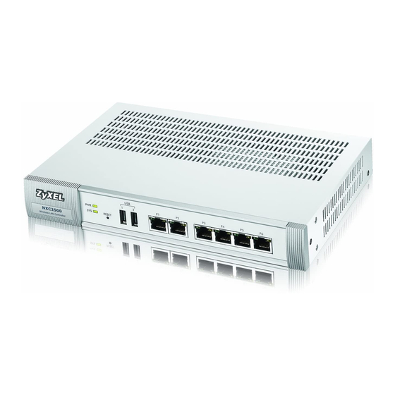
2.2 Front Panel This section gives you an overview of the front panel. 2.2.1 NXC2500 There are LEDs, one reset button, two USB ports and six Ethernet ports on the NXC2500 front panel. Figure 4 Front Panel: NXC2500 2.2.2 NXC5500 There are one reset button, six Ethernet ports, one console port, two USB ports and LEDs on the NXC5500 front panel. - Page 24 Chapter 2 Hardware Installation and Connection Ethernet Ports The auto-negotiating, auto-crossover Ethernet ports support 10/100/1000 Mbps Gigabit Ethernet so the speed can be 10 Mbps, 100 Mbps or 1000 Mbps. The duplex mode can be both half or full duplex at 10/100 Mbps and full duplex only at 1000 Mbps. An auto-negotiating port can detect and adjust to the optimum Ethernet speed and duplex mode of the connected device.
-
Page 25: Front Panel Leds
NXC operating system core dump to it. 2.2.3 Front Panel LEDs This section describes the front panel LEDs. 2.2.3.1 NXC2500 The following table describes the LEDs. Table 7 Front Panel LEDs: NXC2500 COLOR STATUS DESCRIPTION The NXC is turned off. Green The NXC is turned on. -
Page 26: Rear Panel
This Ethernet connection speed is 10 Mbps on this port. (Right) 2.3 Rear Panel The NXC2500 rear panel contains a console port, a power switch and a connector for the power receptacle. Figure 6 Rear Panel: NXC2500 The NXC5500 rear panel contains a power switch, a connector for the power receptacle and a fan module. - Page 27 Chapter 2 Hardware Installation and Connection Connect the male 9-pin end of the RS-232 console cable to the console port of the NXC. Connect the female end to a serial port (COM1, COM2 or other COM port) of your computer. NXC Series User’s Guide...
-
Page 28: The Web Configurator
H A PT ER The Web Configurator 3.1 Overview The NXC Web Configurator allows easy management using an Internet browser. In order to use the Web Configurator, you must: • Use Internet Explorer 7.0 and later versions, Mozilla Firefox 9.0 and later versions, Safari 4.0 and later versions, or Google Chrome 10.0 and later versions. -
Page 29: The Main Screen
Chapter 3 The Web Configurator Click Login. If you logged in using the default user name and password, the Update Admin Info screen appears. Otherwise, the dashboard appears. This screen appears every time you log in using the default user name and default password. If you change the password for the default user account, this screen does not appear anymore. -
Page 30: Title Bar
Chapter 3 The Web Configurator Figure 8 The Web Configurator’s Main Screen • A - Title Bar • B - Navigation Panel • C - Main Window 3.3.1 Title Bar The title bar provides some useful links that always appear over the screens below, regardless of how deep into the Web Configurator you navigate. -
Page 31: Site Map
Chapter 3 The Web Configurator Table 9 Title Bar: Web Configurator Icons (continued) LABEL DESCRIPTION About Click this to display basic information about the NXC. Site Map Click this to see an overview of links to the Web Configurator screens. Object Click this to open a screen where you can check which configuration items reference an object. - Page 32 Chapter 3 The Web Configurator Figure 11 Site Map Object Reference Click Object Reference to open the Object Reference screen. Select the type of object and the individual object and click Refresh to show which configuration settings reference the object. Figure 12 Object Reference The fields vary with the type of object.
- Page 33 Chapter 3 The Web Configurator Table 11 Object References (continued) LABEL DESCRIPTION Priority If it is applicable, this field lists the referencing configuration item’s position in its list, otherwise N/A displays. Name This field identifies the configuration item that references the object. Description If the referencing configuration item has a description configured, it displays here.
- Page 34 Chapter 3 The Web Configurator The following table describes the elements in this screen. Table 12 Console LABEL DESCRIPTION Command Line Enter commands for the device that you are currently logged into here. If you are logged into the NXC, see the CLI Reference Guide for details on using the command line to configure it.
- Page 35 Chapter 3 The Web Configurator Enter the IP address of the NXC and click OK. Next, enter the User Name of the account being used to log into your target device and then click You may be prompted to authenticate your account password, depending on the type of device that you are logging into.
- Page 36 Chapter 3 The Web Configurator If your login is successful, the command line appears and the status bar at the bottom of the Console updates to reflect your connection state. CLI Messages Click CLI to look at the CLI commands sent by the Web Configurator. These commands appear in a popup window, such as the following.
-
Page 37: Navigation Panel
Chapter 3 The Web Configurator 3.3.2 Navigation Panel Use the menu items on the navigation panel to open screens to configure NXC features. Click the arrow in the middle of the right edge of the navigation panel to hide the navigation panel menus or drag it to resize them. -
Page 38: Configuration Menu
Chapter 3 The Web Configurator Table 13 Monitor Menu Screens Summary (continued) FOLDER OR LINK FUNCTION Radio List Display information about the radios of the connected APs. ZyMesh ZyMesh Link Display statistics about the ZyMesh/WDS connections between the Info managed APs. Station Info Station List Display information about the connected stations. - Page 39 Chapter 3 The Web Configurator Table 14 Configuration Menu Screens Summary (continued) FOLDER OR LINK FUNCTION RTLS Real Time Location Use the managed APs as part of an Ekahau RTLS to track the System location of Ekahau Wi-Fi tags. Firewall Firewall Enable or disable the firewall and asymmetrical routes, and configure firewall rules.
-
Page 40: Warning Messages
Chapter 3 The Web Configurator Table 14 Configuration Menu Screens Summary (continued) FOLDER OR LINK FUNCTION SNMP Configure SNMP communities and services. Auth. Server Configure the NXC to act as a RADIUS server. Language Select the Web Configurator language. IPv6 Enables or disables IPv6 support on the NXC. -
Page 41: Tables And Lists
Chapter 3 The Web Configurator 3.3.4 Tables and Lists The Web Configurator tables and lists are quite flexible and provide several options for how to display their entries. Manipulating Table Display Here are some of the ways you can manipulate the Web Configurator tables. Click a column heading to sort the table’s entries according to that column’s criteria. - Page 42 Chapter 3 The Web Configurator Select a column heading cell’s right border and drag to re-size the column. Select a column heading and drag and drop it to change the column order. A green check mark displays next to the column’s title when you drag the column to a valid new location. NXC Series User’s Guide...
- Page 43 Chapter 3 The Web Configurator Use the icons and fields at the bottom of the table to navigate to different pages of entries and control how many entries display at a time. Working with Table Entries The tables have icons for working with table entries. A sample is shown next. You can often use the [Shift] or [Ctrl] key to select multiple entries to remove, activate, or deactivate.
- Page 44 Chapter 3 The Web Configurator Table 17 Common Table Icons (continued) LABEL DESCRIPTION Object Reference Select an entry and click Object Reference to open a screen that shows which settings use the entry. Move To change an entry’s position in a numbered list, select it and click Move to display a field to type a number for where you want to put that entry and press [ENTER] to move the entry to the number that you typed.
-
Page 45: Technical Reference
Technical Reference... -
Page 46: Dashboard
H A PT ER Dashboard 4.1 Overview Use the Dashboard screens to check status information about the NXC. 4.1.1 What You Can Do in this Chapter • The main Dashboard screen (Section 4.2 on page 47) displays the NXC’s general device information, system status, system resource usage, licensed service status, and interface status. -
Page 47: Dashboard
Chapter 4 Dashboard 4.2 Dashboard This screen is the first thing you see when you log into the NXC. It also appears every time you click the Dashboard icon in the navigation panel. The Dashboard displays general device information, system status, system resource usage, licensed service status, and interface status in widgets that you can re-arrange to suit your needs. - Page 48 Chapter 4 Dashboard The following table describes the labels in this screen. Table 18 Dashboard LABEL DESCRIPTION Widget Settings (A) Use this link to re-open closed widgets. Widgets that are already open appear grayed out. Arrow (B) Click this to collapse or expand a widget. Refresh Time Set the interval for refreshing the information displayed in the widget.
- Page 49 Chapter 4 Dashboard Table 18 Dashboard (continued) LABEL DESCRIPTION Boot Status This field displays details about the NXC’s startup state. OK - The NXC started up successfully. Firmware update OK - A firmware update was successful. Problematic configuration after firmware update - The application of the configuration failed after a firmware upgrade.
- Page 50 Chapter 4 Dashboard Table 18 Dashboard (continued) LABEL DESCRIPTION Memory Usage This field displays what percentage of the NXC’s RAM is currently being used. Hover your cursor over this field to display the Show Memory Usage icon that takes you to a chart of the NXC’s recent memory usage.
-
Page 51: Cpu Usage
Chapter 4 Dashboard Table 18 Dashboard (continued) LABEL DESCRIPTION Un-Management This displays the number of non-managed APs. All Station This section displays a summary of connected stations. Click the link to go to the Station Info > Station List screen. Station This displays the number of stations currently connected to the network. -
Page 52: Memory Usage
Chapter 4 Dashboard Table 19 Dashboard > CPU Usage (continued) LABEL DESCRIPTION Refresh Interval Enter how often you want this window to be automatically updated. Refresh Now Click this to update the information in the window right away. 4.2.2 Memory Usage Use this screen to look at a chart of the NXC’s recent memory (RAM) usage. -
Page 53: Dhcp Table
Chapter 4 Dashboard Figure 21 Dashboard > Session Usage The following table describes the labels in this screen. Table 21 Dashboard > Session Usage LABEL DESCRIPTION Sessions The y-axis represents the number of session. The x-axis shows the time period over which the session usage occurred Refresh Interval Enter how often you want this window to be automatically updated. -
Page 54: Number Of Login Users
Chapter 4 Dashboard The following table describes the labels in this screen. Table 22 Dashboard > DHCP Table LABEL DESCRIPTION This field is a sequential value, and it is not associated with a specific entry. Interface This field identifies the interface that assigned an IP address to a DHCP client. IP Address This field displays the IP address currently assigned to a DHCP client or reserved for a specific MAC address. - Page 55 Chapter 4 Dashboard The following table describes the labels in this screen. Table 23 Dashboard > Number of Login Users LABEL DESCRIPTION This field is a sequential value and is not associated with any entry. User ID This field displays the user name of each user who is currently logged in to the NXC. Reauth Lease T.
-
Page 56: Monitor
H A PT ER Monitor 5.1 Overview Use the Monitor screens to check status and statistics information. 5.1.1 What You Can Do in this Chapter • The Port Statistics screen (Section 5.3 on page 57) displays packet statistics for each physical port. -
Page 57: What You Need To Know
Chapter 5 Monitor 5.2 What You Need to Know The following terms and concepts may help as you read through the chapter. Rogue AP Rogue APs are wireless access points operating in a network’s coverage area that are not under the control of the network’s administrators, and can open up holes in a network’s security. -
Page 58: Port Statistics Graph
Chapter 5 Monitor Table 24 Monitor > System Status > Port Statistics (continued) LABEL DESCRIPTION This field displays the port’s number in the list. Port This field displays the physical port number. Status This field displays the current status of the physical port. Down - The physical port is not connected. -
Page 59: Interface Status
Chapter 5 Monitor Figure 25 Monitor > System Status > Port Statistics > Switch to Graphic View The following table describes the labels in this screen. Table 25 Monitor > System Status > Port Statistics > Switch to Graphic View LABEL DESCRIPTION Refresh Interval... - Page 60 Chapter 5 Monitor Figure 26 Monitor > System Status > Interface Status Each field is described in the following table. Table 26 Monitor > System Status > Interface Status LABEL DESCRIPTION Interface Status Use the Interface Status section for IPv4 network settings. Use the IPv6 Interface Status section for IPv6 network settings if you connect your NXC to an IPv6 network.
- Page 61 Chapter 5 Monitor Table 26 Monitor > System Status > Interface Status (continued) LABEL DESCRIPTION Status This field displays the current status of each interface. The possible values depend on what type of interface it is. For Ethernet interfaces: Inactive - The Ethernet interface is disabled. Down - The Ethernet interface is enabled but not connected.
-
Page 62: Traffic Statistics
Chapter 5 Monitor Table 26 Monitor > System Status > Interface Status (continued) LABEL DESCRIPTION Status This field displays the current status of each interface. The possible values depend on what type of interface it is. For Ethernet interfaces: Inactive - The Ethernet interface is disabled. Down - The Ethernet interface is enabled but not connected. - Page 63 Chapter 5 Monitor Figure 27 Monitor > System Status > Traffic Statistics There is a limit on the number of records shown in the report. See Table 28 on page 64 for more information. The following table describes the labels in this screen. Table 27 Monitor >...
- Page 64 Chapter 5 Monitor Table 27 Monitor > System Status > Traffic Statistics (continued) LABEL DESCRIPTION Direction This field indicates whether the IP address or user is sending or receiving traffic. Rx From- traffic is coming from the IP address or user to the NXC. Tx To - traffic is going from the NXC to the IP address or user.
-
Page 65: Session Monitor
Chapter 5 Monitor 5.6 Session Monitor This screen displays information about active sessions for debugging or statistical analysis. It is not possible to manage sessions in this screen. The following information is displayed. • User who started the session • Protocol or service port used •... - Page 66 Chapter 5 Monitor The following table describes the labels in this screen. Table 29 Monitor > System Status > Session Monitor LABEL DESCRIPTION View Select how you want the information to be displayed. Choices are: sessions by users - display all active sessions grouped by user sessions by services - display all active sessions grouped by service or protocol sessions by source IP - display all active sessions grouped by source IP address sessions by destination IP - display all active sessions grouped by destination IP...
-
Page 67: Ip/Mac Binding Monitor
Chapter 5 Monitor 5.7 IP/MAC Binding Monitor Click Monitor > System Status > IP/MAC Binding to display the following screen. This screen lists the devices that have received an IP address from NXC interfaces with IP/MAC binding enabled and have ever established a session with the NXC. Devices that have never established a session with the NXC do not display in the list. - Page 68 Chapter 5 Monitor Figure 30 Monitor > System Status > Login Users The following table describes the labels in this screen. Table 31 Monitor > System Status > Login Users LABEL DESCRIPTION Force Logout Select a user ID and click this icon to end a user’s session. This field is a sequential value and is not associated with any entry.
-
Page 69: Dynamic Guest
Chapter 5 Monitor 5.9 Dynamic Guest A dynamic guest account has a dynamically-created user name and password that allows a guest user to access the Internet or the NXC’s services in a specified period of time. Multiple dynamic guest accounts can be automatically generated at one time for guest users by using the web configurator and the guest-manager account. -
Page 70: Usb Storage
Chapter 5 Monitor 5.10 USB Storage This screen displays information about a connected USB storage device. Click Monitor > System Status > USB Storage to display this screen. Figure 32 Monitor > System Status > USB Storage The following table describes the labels in this screen. Table 33 Monitor >... -
Page 71: Ap List
Chapter 5 Monitor 5.11 AP List Use this screen to view which APs are currently connected to the NXC. To access this screen, click Monitor > Wireless > AP Information > AP List. Figure 33 Monitor > Wireless > AP Information > AP List The following table describes the labels in this screen. -
Page 72: Station Count Of Ap
Chapter 5 Monitor Table 34 Monitor > Wireless > AP Information > AP List (continued) LABEL DESCRIPTION Last Off-line This displays the most recent time the AP went off-line. N/A displays if the AP has either Time not come on-line or gone off-line since the NXC last started up. LED Status This displays the AP LED status. - Page 73 Chapter 5 Monitor Figure 34 Monitor > Wireless > AP Information > AP List > AP Information The following table describes the labels in this screen. Table 36 Monitor > Wireless > AP Information > AP List > AP Information LABEL DESCRIPTION Configuration...
-
Page 74: Config Ap
Chapter 5 Monitor Table 36 Monitor > Wireless > AP Information > AP List > AP Information (continued) LABEL DESCRIPTION Status This field displays the current status of each physical port on the AP. Down - The port is not connected. Speed / Duplex - The port is connected. - Page 75 Chapter 5 Monitor Figure 35 Monitor > Wireless > AP Information > AP List > Config AP NXC Series User’s Guide...
- Page 76 Chapter 5 Monitor The following table describes the labels in this screen. Table 37 Monitor > Wireless > AP Information > AP List > Config AP LABEL DESCRIPTION Create new Object Use this menu to create a new Radio Profile, MON Profile, SSID Profile or ZyMesh Profile object to associate with this AP.
- Page 77 Chapter 5 Monitor Table 37 Monitor > Wireless > AP Information > AP List > Config AP (continued) LABEL DESCRIPTION Edit Select an SSID and click this button to reassign it. The selected SSID becomes editable immediately upon clicking. This is the index number of the SSID profile. You can associate up to eight SSID profiles with an AP radio.
-
Page 78: Radio List
Chapter 5 Monitor Table 37 Monitor > Wireless > AP Information > AP List > Config AP (continued) LABEL DESCRIPTION Click OK to save your changes back to the NXC. Cancel Click Cancel to close the window with changes unsaved. 5.12 Radio List Use this screen to view statistics about the wireless radio transmitters in each of the APs connected to the NXC. -
Page 79: Ap Mode Radio Information
Chapter 5 Monitor Table 38 Monitor > Wireless > AP Information > Radio List (continued) LABEL DESCRIPTION Station This displays the number of stations (aka wireless clients) associated with the radio. Rx PKT This displays the total number of packets received by the radio. Tx PKT This displays the total number of packets transmitted by the radio. - Page 80 Chapter 5 Monitor Figure 37 Monitor > Wireless > AP Information > Radio List > AP Mode Radio Information NXC Series User’s Guide...
-
Page 81: Zymesh Link Info
Chapter 5 Monitor The following table describes the labels in this screen. Table 40 Monitor > Wireless > AP Info > Radio List > AP Mode Radio Information LABEL DESCRIPTION MBSSID Detail This list shows information about the SSID(s) that is associated with the radio over the preceding 24 hours. -
Page 82: Station List
Chapter 5 Monitor The following table describes the labels in this screen. Table 41 Monitor > Wireless > ZyMesh > ZyMesh Link Info LABEL DESCRIPTION This is the index number of the managed AP (in repeater mode) in this list. Description This is the descriptive name of the managed AP (in repeater mode). -
Page 83: Detected Device
Chapter 5 Monitor The following table describes the labels in this screen. Table 42 Monitor > Wireless > Station Info > Station List LABEL DESCRIPTION This is the station’s index number in this list. MAC Address This is the station’s MAC address. Associated AP This indicates the AP through which the station is connected to the network. -
Page 84: View Log
Chapter 5 Monitor The following table describes the labels in this screen. Table 43 Monitor > Wireless > Rogue AP > Detected Device LABEL DESCRIPTION Mark as Rogue Click this button to mark the selected AP as a rogue AP. A rogue AP can be contained in the Configuration >... - Page 85 Chapter 5 Monitor Figure 41 Monitor > View Log The following table describes the labels in this screen. Table 44 Monitor > View Log LABEL DESCRIPTION Show Filter / Click this button to show or hide the filter settings. Hide Filter If the filter settings are hidden, the Display, Email Log Now, Refresh, and Clear Log fields are available.
-
Page 86: View Ap Log
Chapter 5 Monitor Table 44 Monitor > View Log (continued) LABEL DESCRIPTION Keyword This displays when you show the filter. Type a keyword to look for in the Message, Source, Destination and Note fields. If a match is found in any field, the log message is displayed. - Page 87 Chapter 5 Monitor Figure 42 Monitor > Log > View AP Log The following table describes the labels in this screen. Table 45 Monitor > Log > View AP Log LABEL DESCRIPTION Show/Hide Filter Click this to show or hide the AP log filter. Select an AP Select an AP from the list and click Query to view its log messages.
- Page 88 Chapter 5 Monitor Table 45 Monitor > Log > View AP Log LABEL DESCRIPTION Destination Enter a destination IP address to display only the log messages that include it. Address Note: This criterion only appears when you Show Filter. Source Interface Enter a source interface to display only the log messages that include it.
-
Page 89: Registration
Note: To activate a service on a NXC, you need to access myZyXEL.com via that NXC. Maximum Number of Managed APs The NXC2500 is initially configured to support up to 8 managed APs (such as the NWA5123-NI). You can increase this by subscribing to additional licenses. As of this writing, each license upgrade... -
Page 90: Registration
Chapter 6 Registration Maximum Number of ZyMesh Root APs The NXC by default allows up to one ZyMesh root AP, which means only one radio of the managed AP can be set to root AP mode. You can remove the limit by subscribing to the ZyMesh license. 6.2 Registration Click the link in this screen to register your NXC with myZyXEL.com. - Page 91 Chapter 6 Registration The following table describes the labels in this screen. Table 46 Configuration > Licensing > Registration > Service LABEL DESCRIPTION License Status This is the entry’s position in the list. Service This lists the services that are available on the NXC. Status This field displays whether this is a default service (Default) or an activated license upgrade (Licensed).
-
Page 92: Wireless
H A PT ER Wireless 7.1 Overview Use the Wireless screens to configure how the NXC manages the Access Point that are connected to it. 7.1.1 What You Can Do in this Chapter • The Controller screen (Section 7.2 on page 93) sets how the NXC allows new APs to connect to the network. -
Page 93: Controller
Chapter 7 Wireless 7.2 Controller Use this screen to set how the NXC allows new APs to connect to the network. Click Configuration > Wireless > Controller to access this screen. Figure 45 Configuration > Wireless > Controller Each field is described in the following table. Table 47 Configuration >... -
Page 94: Ap Management
Chapter 7 Wireless 7.3 AP Management Use this screen to manage all of the APs connected to the NXC. Click Configuration > Wireless > AP Management to access this screen. Figure 46 Configuration > Wireless > AP Management Each field is described in the following table. Table 48 Configuration >... - Page 95 Chapter 7 Wireless Table 48 Configuration > Wireless > AP Management (continued) LABEL DESCRIPTION R1 Mode / Profile / This field displays the operating mode (AP, MON, root, or repeater), AP radio profile ZyMesh Profile name and ZyMesh profile name for Radio 1. It displays n/a for the AP profile for a radio not using an AP profile or - for the ZyMesh profile for a radio not using a ZyMesh profile.
-
Page 96: Edit Ap List
Chapter 7 Wireless 7.3.1 Edit AP List Select an AP and click the Edit button in the Configuration > Wireless > AP Management table to display this screen. Figure 47 Configuration > Wireless > AP Management > Edit AP List NXC Series User’s Guide... - Page 97 Chapter 7 Wireless Each field is described in the following table. Table 49 Configuration > Wireless > AP Management > Edit AP List LABEL DESCRIPTION Create new Object Use this menu to create a new Radio Profile, MON Profile or ZyMesh Profile object to associate with this AP.
-
Page 98: Port Setting Edit
Chapter 7 Wireless Table 49 Configuration > Wireless > AP Management > Edit AP List (continued) LABEL DESCRIPTION Edit Select an SSID and click this button to reassign it. The selected SSID becomes editable immediately upon clicking. This is the index number of the SSID profile. You can associate up to eight SSID profiles with an AP radio. -
Page 99: Vlan Add/Edit
Chapter 7 Wireless Figure 48 Configuration > Wireless > AP Management > Edit AP List > Edit Port Each field is described in the following table. Table 50 Configuration > Wireless > AP Management > Edit AP List > Edit Port LABEL DESCRIPTION Enable... - Page 100 Chapter 7 Wireless Figure 49 Configuration > Wireless > AP Management > Edit AP List > Edit VLAN Each field is described in the following table. Table 51 Configuration > Wireless > AP Management > Edit AP List > Edit VLAN LABEL DESCRIPTION Enable...
-
Page 101: Ap Policy
Chapter 7 Wireless 7.3.4 AP Policy Use this screen to configure the AP controller’s IP address on the managed APs and determine the action the managed APs take if the current AP controller fails. Click Configuration > Wireless > AP Management > AP Policy to access this screen. Figure 50 Configuration >... -
Page 102: Ap Group
Chapter 7 Wireless Table 52 Configuration > Wireless > AP Management > AP Policy (continued) LABEL DESCRIPTION Apply Click Apply to save your changes back to the NXC. Reset Click Reset to return the screen to its last-saved settings. 7.3.5 AP Group Use this screen to configure AP groups, which define the radio, port, VLAN and load balancing settings and apply the settings to all APs in the group. - Page 103 Chapter 7 Wireless Table 53 Configuration > Wireless > AP Management > AP Group (continued) LABEL DESCRIPTION Group Name This is the name of the group. Member Count This is the total number of APs which belong to this group. Apply Click Apply to save your changes back to the NXC.
-
Page 104: Add/Edit Ap Group
Chapter 7 Wireless 7.3.6 Add/Edit AP Group Click Add or select an AP group and click the Edit button in the Configuration > Wireless > AP Management > AP Group table to display this screen. Figure 52 Configuration > Wireless > AP Management > AP Group > Add/Edit NXC Series User’s Guide... - Page 105 Chapter 7 Wireless Each field is described in the following table. Table 54 Configuration > Wireless > AP Management > AP Group > Add/Edit LABEL DESCRIPTION General Settings Group Name Enter a name for this group. You can use up to 31 alphanumeric characters. Dashes and underscores are also allowed.
- Page 106 Chapter 7 Wireless Table 54 Configuration > Wireless > AP Management > AP Group > Add/Edit (continued) LABEL DESCRIPTION As Native VLAN Select this option to treat this VLAN ID as a VLAN created on the NXC and not one assigned to it from outside the network.
-
Page 107: Mon Mode
Chapter 7 Wireless Table 54 Configuration > Wireless > AP Management > AP Group > Add/Edit (continued) LABEL DESCRIPTION Disassociate This function is enabled by default and the disassociation priority is always Signal station when Strength when you set Mode to By Smart Classroom. overloaded Select this option to disassociate wireless clients connected to the AP when it becomes overloaded. - Page 108 Chapter 7 Wireless Figure 53 Configuration > Wireless > MON Mode Each field is described in the following table. Table 55 Configuration > Wireless > MON Mode LABEL DESCRIPTION General Settings Enable Rogue AP Select this to enable rogue AP containment. Containment Rogue/Friendly AP List Click this button to add an AP to the list and assign it either friendly or rogue...
-
Page 109: Add/Edit Rogue/Friendly List
Chapter 7 Wireless Table 55 Configuration > Wireless > MON Mode (continued) LABEL DESCRIPTION File Path / Browse / Enter the file name and path of the list you want to import or click the Browse Importing button to locate it. Once the File Path field has been populated, click Importing to bring the list into the NXC. -
Page 110: Auto Healing
Chapter 7 Wireless 7.5 Auto Healing Use this screen to enable auto healing, which allows you to extend the wireless service coverage area of the managed APs when one of the APs fails. Click Configuration > Wireless > Auto Healing to access this screen. Figure 55 Configuration >... -
Page 111: Technical Reference
Chapter 7 Wireless 7.6 Technical Reference The following section contains additional technical information about the features described in this chapter. 7.6.1 Dynamic Channel Selection When numerous APs broadcast within a given area, they introduce the possibility of heightened radio interference, especially if some or all of them are broadcasting on the same radio channel. If the interference becomes too great, then the network administrator must open his AP configuration options and manually change the channel to one that no other AP is using (or at least a channel that has a lower level of interference) in order to give the connected stations a minimum degree of... -
Page 112: Load Balancing
Chapter 7 Wireless Finally, there is an alternative four channel scheme for ETSI, consisting of channels 1, 5, 9, 13. This offers significantly less overlap that the other one. Figure 58 An Alternative Four-Channel Deployment 7.6.2 Load Balancing Because there is a hard upper limit on an AP’s wireless bandwidth, load balancing can be crucial in areas crowded with wireless users. -
Page 113: Disassociating And Delaying Connections
Chapter 7 Wireless 7.6.3 Disassociating and Delaying Connections When your AP becomes overloaded, there are two basic responses it can take. The first one is to “delay” a client connection. This means that the AP withholds the connection until the data transfer throughput is lowered or the client connection is picked up by another AP. -
Page 114: Interfaces
H A PT ER Interfaces 8.1 Interface Overview Use these screens to configure the NXC’s interfaces. • Ports are the physical ports to which you connect cables. • Interfaces are used within the system operationally. You use them in configuring various features. -
Page 115: Ethernet Summary
Chapter 8 Interfaces 8.2 Ethernet Summary This screen lists every Ethernet interface. If you enabled IPv6 in the Configuration > System > IPv6 screen, you can also configure VLAN interfaces used for your IPv6 networks on this screen. To access this screen, click Configuration > Network > Interface. Unlike other types of interfaces, you cannot create new Ethernet interfaces nor can you delete any of them. -
Page 116: Edit Ethernet
Chapter 8 Interfaces Each field is described in the following table. Table 58 Configuration > Network > Interface > Ethernet LABEL DESCRIPTION Configuration/IPv6 Use the Configuration section for IPv4 network settings. Use the IPv6 Configuration Configuration section for IPv6 network settings if you connect your NXC to an IPv6 network. Both sections have similar fields as described below. - Page 117 Chapter 8 Interfaces Figure 62 Configuration > Network > Interface > Ethernet > Edit (general) NXC Series User’s Guide...
- Page 118 Chapter 8 Interfaces This screen’s fields are described in the table below. Table 59 Configuration > Network > Interface > Ethernet > Edit LABEL DESCRIPTION IPv4/IPv6 View / Use this button to display both IPv4 and IPv6, IPv4-only, or IPv6-only configuration IPv4 View / IPv6 fields.
- Page 119 Chapter 8 Interfaces Table 59 Configuration > Network > Interface > Ethernet > Edit (continued) LABEL DESCRIPTION Subnet Mask This field is enabled if you set the Interface Type to internal or you select Use Fixed IP Address. Enter the subnet mask of this interface in dot decimal notation. The subnet mask indicates what part of the IP address is the same for all computers in the network.
- Page 120 Chapter 8 Interfaces Table 59 Configuration > Network > Interface > Ethernet > Edit (continued) LABEL DESCRIPTION Click this to create an entry in this table. See Section 8.2.3 on page 123 for more information. Remove Select an entry and click this to delete it from this table. Object Select an entry and click Object Reference to open a screen that shows which settings Reference...
- Page 121 Chapter 8 Interfaces Table 59 Configuration > Network > Interface > Ethernet > Edit (continued) LABEL DESCRIPTION DHCP Select what type of DHCP service the NXC provides to the network. Choices are: None - the NXC does not provide any DHCP services. There is already a DHCP server on the network.
- Page 122 Chapter 8 Interfaces Table 59 Configuration > Network > Interface > Ethernet > Edit (continued) LABEL DESCRIPTION Edit Select an entry in this table and click this to modify it. Remove Select an entry in this table and click this to delete it. This field is a sequential value, and it is not associated with any entry.
-
Page 123: Object References
Chapter 8 Interfaces 8.2.2 Object References When a configuration screen includes an Object Reference icon, select a configuration object and click Object Reference to open the Object References screen. This screen displays which configuration settings reference the selected object. The fields shown vary with the type of object. Figure 63 Object References The following table describes labels that can appear in this screen. -
Page 124: Add/Edit Dhcp Extended Options
Chapter 8 Interfaces Figure 64 Configuration > Network > Interface > Ethernet > Edit > Add DHCPv6 Request Options 8.2.4 Add/Edit DHCP Extended Options When you configure an interface as a DHCPv4 server, you can additionally add DHCP extended options which have the NXC to add more information in the DHCP packets. The available fields vary depending on the DHCP option you select in this screen. - Page 125 Chapter 8 Interfaces Table 61 Configuration > Network > Interface > Ethernet > Edit > Add/Edit Extended Options LABEL DESCRIPTION Value Enter the value for the selected DHCP option. For example, if you selected TFTP Server Name (66) and the type is TEXT, enter the DNS domain name of a TFTP server here. This field is mandatory.
-
Page 126: Vlan Interfaces
Chapter 8 Interfaces Table 62 DHCP Extended Options (continued) OPTION NAME CODE DESCRIPTION CAPWAP AC CAPWAP Access Controller addresses option The Control And Provisioning of Wireless Access Points Protocol allows a Wireless Termination Point (WTP) to use DHCP to discover the Access Controllers to which it is to connect. -
Page 127: Vlan Summary
Chapter 8 Interfaces Figure 67 Example: After VLAN Each VLAN is a separate network with separate IP addresses, subnet masks, and gateways. Each VLAN also has a unique identification number (ID). The ID is a 12-bit value that is stored in the MAC header. - Page 128 Chapter 8 Interfaces Figure 68 Configuration > Network > Interface > VLAN Each field is explained in the following table. Table 63 Configuration > Network > Interface > VLAN LABEL DESCRIPTION Configuration / Use the Configuration section for IPv4 network settings. Use the IPv6 Configuration IPv6 section for IPv6 network settings if you connect your NXC to an IPv6 network.
-
Page 129: Add/Edit Vlan
Chapter 8 Interfaces 8.3.2 Add/Edit VLAN This screen lets you configure IP address assignment, interface bandwidth parameters, DHCP settings, and connectivity check for each VLAN interface. To access this screen, click the Add icon at the top of the Add column or click an Edit icon next to a VLAN interface in the VLAN Summary screen. - Page 130 Chapter 8 Interfaces Figure 69 Configuration > Network > Interface > VLAN > Add/Edit NXC Series User’s Guide...
- Page 131 Chapter 8 Interfaces Each field is explained in the following table. Table 64 Configuration > Network > Interface > VLAN > Add/Edit LABEL DESCRIPTION IPv4/IPv6 View / Use this button to display both IPv4 and IPv6, IPv4-only, or IPv6-only configuration IPv4 View / IPv6 fields.
- Page 132 Chapter 8 Interfaces Table 64 Configuration > Network > Interface > VLAN > Add/Edit (continued) LABEL DESCRIPTION Metric Enter the priority of the gateway (if any) on this interface. The NXC decides which gateway to use based on this priority. The lower the number, the higher the priority. If two or more gateways have the same priority, the NXC uses the one that was configured first.
- Page 133 Chapter 8 Interfaces Table 64 Configuration > Network > Interface > VLAN > Add/Edit (continued) LABEL DESCRIPTION Interface Parameters Egress Enter the maximum amount of traffic, in kilobits per second, the NXC can send through Bandwidth the interface to the network. Allowed values are 0 - 1048576. Ingress This is reserved for future use.
- Page 134 Chapter 8 Interfaces Table 64 Configuration > Network > Interface > VLAN > Add/Edit (continued) LABEL DESCRIPTION Lease time Specify how long each computer can use the information (especially the IP address) before it has to request the information again. Choices are: infinite - select this if IP addresses never expire days, hours, and minutes - select this to enter how long IP addresses are valid.
-
Page 135: Technical Reference
Chapter 8 Interfaces Table 64 Configuration > Network > Interface > VLAN > Add/Edit (continued) LABEL DESCRIPTION Click OK to save your changes back to the NXC. Cancel Click Cancel to exit this screen without saving. 8.4 Technical Reference The following section contains additional technical information about the features described in this chapter. -
Page 136: Dhcp Settings
Chapter 8 Interfaces If you set the bandwidth restrictions very high, you effectively remove the restrictions. The NXC also restricts the size of each data packet. The maximum number of bytes in each packet is called the maximum transmission unit (MTU). If a packet is larger than the MTU, the NXC divides it into smaller fragments. - Page 137 Chapter 8 Interfaces • Subnet mask - The interface provides the same subnet mask you specify for the interface. • Gateway - The interface provides the same gateway you specify for the interface. • DNS servers - The interface provides IP addresses for up to three DNS servers that provide DNS services for DHCP clients.
-
Page 138: Policy And Static Routes
H A PT ER Policy and Static Routes 9.1 Overview Use policy routes and static routes to override the NXC’s default routing behavior in order to send packets through the appropriate interface. 9.1.1 What You Can Do in this Chapter •... -
Page 139: Policy Route
Chapter 9 Policy and Static Routes • Policy routes are only used within the NXC itself. Static routes can be propagated to other routers. • Policy routes take priority over static routes. If you need to use a routing policy on the NXC and propagate it to other routers, you could configure a policy route and an equivalent static route. - Page 140 Chapter 9 Policy and Static Routes IPPR follows the existing packet filtering facility of RAS in style and in implementation. Figure 70 Configuration > Network > Routing > Policy Route The following table describes the labels in this screen. Table 67 Configuration > Network > Routing > Policy Route LABEL DESCRIPTION Show / Hide...
-
Page 141: Add/Edit Policy Route
Chapter 9 Policy and Static Routes Table 67 Configuration > Network > Routing > Policy Route (continued) LABEL DESCRIPTION DSCP Code This is the DSCP value of incoming packets to which this policy route applies. any means all DSCP values or no DSCP marker. default means traffic with a DSCP value of 0. - Page 142 Chapter 9 Policy and Static Routes Figure 71 Configuration > Network > Routing > Policy Route > Add/Edit The following table describes the labels in this screen. Table 68 Configuration > Network > Routing > Policy Route > Add/Edit LABEL DESCRIPTION Show / Hide Click this button to display a greater or lesser number of configuration fields.
- Page 143 Chapter 9 Policy and Static Routes Table 68 Configuration > Network > Routing > Policy Route > Add/Edit (continued) LABEL DESCRIPTION Destination Select a destination IP address object to which the traffic is being sent. Address DSCP Code Select a DSCP code point value of incoming packets to which this policy route applies or select User Defined to specify another DSCP code point.
-
Page 144: Static Route
Chapter 9 Policy and Static Routes Table 68 Configuration > Network > Routing > Policy Route > Add/Edit (continued) LABEL DESCRIPTION Source Network Select none to not use NAT for the route. Address Select outgoing-interface to use the IP address of the outgoing interface as the source Translation IP address of the packets that matches this route. -
Page 145: Static Route Setting
Chapter 9 Policy and Static Routes 9.3.1 Static Route Setting Select a static route index number and click Add or Edit. The screen shown next appears. Use this screen to configure the required information for a static route. Figure 73 Configuration > Network > Routing > Static Route > Add/Edit The following table describes the labels in this screen. - Page 146 Chapter 9 Policy and Static Routes NAT and SNAT NAT (Network Address Translation - NAT, RFC 1631) is the translation of the IP address in a packet in one network to a different IP address in another network. Use SNAT (Source NAT) to change the source IP address in one network to a different IP address in another network.
- Page 147 Chapter 9 Policy and Static Routes BEST EFFORT: All wireless traffic to the SSID is tagged as “best effort,” meaning the data travels the best route it can without displacing higher priority traffic. This is good for activities that do not require the best bandwidth throughput, such as surfing the Internet.
-
Page 148: Zones
HAPTER Zones 10.1 Overview Set up zones to configure network security and network policies in the NXC. A zone is a group of interfaces. The NXC uses zones instead of interfaces in many security and policy settings, such as firewall rules. Zones cannot overlap. Each interface can be assigned to just one zone. 10.1.1 What You Can Do in this Chapter The Zone screens (see Section 10.2 on page... -
Page 149: Zone
Chapter 10 Zones 10.2 Zone The Zone screen provides a summary of all zones. In addition, this screen allows you to add, edit, and remove zones. To access this screen, click Configuration > Network > Zone. Figure 74 Configuration > Network > Zone The following table describes the labels in this screen. - Page 150 Chapter 10 Zones Figure 75 Network > Zone > Add/Edit The following table describes the labels in this screen. Table 74 Network > Zone > Add/Edit LABEL DESCRIPTION Name Type the name used to refer to the zone. You may use 1-31 alphanumeric characters, underscores( ), or dashes (-), but the first character cannot be a number.
-
Page 151: Nat
HAPTER 11.1 Overview NAT (Network Address Translation - NAT, RFC 1631) is the translation of the IP address of a host in a packet. For example, the source address of an outgoing packet, used within one network is changed to a different IP address known within another network. Use Network Address Translation (NAT) to make computers on a private network behind the NXC available outside the private network. -
Page 152: Add/Edit Nat
Chapter 11 NAT Figure 77 Configuration > Network > NAT The following table describes the labels in this screen. Table 75 Configuration > Network > NAT LABEL DESCRIPTION Click this to create a new entry. Edit Double-click an entry or select it and click Edit to open a screen where you can modify the entry’s settings. - Page 153 Chapter 11 NAT Figure 78 Configuration > Network > NAT > Add/Edit The following table describes the labels in this screen. Table 76 Configuration > Network > NAT > Add/Edit LABEL DESCRIPTION Create new Use to configure any new settings objects that you need to use in this screen. Object Enable Rule Use this option to turn the NAT rule on or off.
- Page 154 Chapter 11 NAT Table 76 Configuration > Network > NAT > Add/Edit (continued) LABEL DESCRIPTION Classification Select what kind of NAT this rule is to perform. Virtual Server - This makes computers on a private network behind the NXC available to a public network outside the NXC (like the Internet).
- Page 155 Chapter 11 NAT Table 76 Configuration > Network > NAT > Add/Edit (continued) LABEL DESCRIPTION Port Mapping Use the drop-down list box to select how many original destination ports this NAT rule Type supports for the selected destination IP address (Original IP). Choices are: Any - this NAT rule supports all the destination ports.
-
Page 156: Technical Reference
Chapter 11 NAT 11.3 Technical Reference The following section contains additional technical information about the features described in this chapter. NAT Loopback Suppose a NAT 1:1 rule maps a public IP address to the private IP address of a LAN SMTP e-mail server to give WAN users access. - Page 157 Chapter 11 NAT Figure 80 LAN to LAN Traffic Source 192.168.1.1 Source 192.168.1.89 SMTP SMTP 192.168.1.21 192.168.1.89 The LAN SMTP server replies to the NXC’s LAN IP address and the NXC changes the source address to 1.1.1.1 before sending it to the LAN user. The return traffic’s source matches the original destination address (1.1.1.1).
-
Page 158: Alg
HAPTER 12.1 Overview Application Layer Gateway (ALG) allows the following application to operate properly through the NXC’s NAT. • FTP - File Transfer Protocol - an Internet file transfer service. The ALG feature is only needed for traffic that goes through the NXC’s NAT. 12.1.1 What You Can Do in this Chapter The ALG screen (Section 12.2 on page... -
Page 159: Technical Reference
Chapter 12 ALG Figure 82 Configuration > Network > ALG The following table describes the labels in this screen. Table 77 Configuration > Network > ALG LABEL DESCRIPTION Enable FTP ALG Turn on the FTP ALG to detect FTP (File Transfer Program) traffic and help build FTP sessions through the NXC’s NAT. -
Page 160: Ip/Mac Binding
HAPTER IP/MAC Binding 13.1 Overview IP address to MAC address binding helps ensure that only the intended devices get to use privileged IP addresses. The NXC uses DHCP to assign IP addresses and records to MAC address it assigned each IP address. The NXC then checks incoming connection attempts against this list. A user cannot manually assign another IP to his computer and use it to connect to the NXC. -
Page 161: Ip/Mac Binding Summary
Chapter 13 IP/MAC Binding Interfaces Used With IP/MAC Binding IP/MAC address bindings are grouped by interface. You can use IP/MAC binding with Ethernet and VLAN interfaces. You can also enable or disable IP/MAC binding and logging in an interface’s configuration screen. 13.2 IP/MAC Binding Summary Click Configuration >... -
Page 162: Edit Ip/Mac Binding
Chapter 13 IP/MAC Binding 13.2.1 Edit IP/MAC Binding Click Configuration > Network > IP/MAC Binding > Edit to open this screen. Use this screen to configure an interface’s IP to MAC address binding settings. Figure 85 Configuration > Network > IP/MAC Binding > Edit The following table describes the labels in this screen. -
Page 163: Add/Edit Static Dhcp Rule
Chapter 13 IP/MAC Binding Table 79 Configuration > Network > IP/MAC Binding > Edit (continued) LABEL DESCRIPTION IP Address This is the IP address that the NXC assigns to a device with the entry’s MAC address. MAC Address This is the MAC address of the device to which the NXC assigns the entry’s IP address. Description This helps identify the entry. - Page 164 Chapter 13 IP/MAC Binding Figure 87 Configuration > Network > IP/MAC Binding > Exempt List The following table describes the labels in this screen. Table 81 Configuration > Network > IP/MAC Binding > Exempt List LABEL DESCRIPTION Click this to create a new entry. Edit Click an entry or select it and click Edit to modify the entry’s settings.
-
Page 165: Captive Portal
HAPTER Captive Portal 14.1 Overview A captive portal can intercepts network traffic, according to the authentication policies, until the user authenticates his or her connection, usually through a specifically designated login web page. As an added security measure, the NXC contains captive portal functionality. This means all web page requests can initially be redirected to a special web page that requires you to authenticate your session. -
Page 166: Captive Portal Type
Chapter 14 Captive Portal 14.1.1 Captive Portal Type The NXC allows you to use either an internal captive web portal (built into the NXC) or external captive web portal (on an external web server). You can even customize the portal page(s). See Section 14.3.1 on page 175 Section 14.3.2 on page 177 for portal pages details. -
Page 167: Captive Portal
Chapter 14 Captive Portal 14.2 Captive Portal This screen allows you to configure which HTTP-based network services default to the captive portal page when client makes an initial network connection. Click Configuration > Captive Portal to access this screen. Note: You can configure the look and feel of the captive portal web page on the Login Page screen;... - Page 168 Chapter 14 Captive Portal The following table describes the labels in this screen. Table 83 Configuration > Captive Portal LABEL DESCRIPTION Enable Captive Select this to turn on the captive portal feature. Portal Once enabled, all network traffic is blocked until a client authenticates with the NXC through the specifically designated captive portal page.
- Page 169 Chapter 14 Captive Portal Table 83 Configuration > Captive Portal (continued) LABEL DESCRIPTION QR Content Select a VLAN interface on the NXC, through which the authenticator is allowed to access the NXC. Authenticato Select a user account or user group that you created in the Object > User/Group screen to act as an authenticator.
-
Page 170: Add Exceptional Services
Chapter 14 Captive Portal Table 83 Configuration > Captive Portal (continued) LABEL DESCRIPTION Priority This indicates the priority of a policy. Priority values are unique to each policy. If you want to adjust the priority, use the Move button. Source This indicates the source IP address to be monitored by the policy. -
Page 171: Auth. Policy Add/Edit
Chapter 14 Captive Portal The following table describes the labels in this screen. Table 84 Configuration > Captive Portal > Add Exceptional Services LABEL DESCRIPTION Available This lists all available network services eligible for being excepted from captive portal interception. Member This lists all networks services currently assigned to the Exceptional Services table. - Page 172 Chapter 14 Captive Portal Table 85 Configuration > Captive Portal > Auth. Policy Add/Edit LABEL DESCRIPTION Source Address Select an address object from the list. If none are available, you can create a new one using the Create New Object button. The source address is an IP address for which the captive portal intercepts all network traffic.
-
Page 173: Login Page
Chapter 14 Captive Portal 14.3 Login Page The login page appears whenever the captive portal intercepts network traffic, preventing unauthorized users from gaining access to the network. Use this page to select the default login page or customize it. Click Configuration > Captive Portal > Login Page to display it. Figure 92 Configuration >... - Page 174 Chapter 14 Captive Portal The following table describes the labels in this screen. Table 86 Configuration > Captive Portal > Login Page LABEL DESCRIPTION Select Type Use Default Login Select this to use the default login page built into the device. If you later create a custom Page login page, you can still return to the NXC’s default page as it is saved indefinitely.
-
Page 175: Custom Login And Access
Chapter 14 Captive Portal Table 86 Configuration > Captive Portal > Login Page LABEL DESCRIPTION Note Message Enter a note to display below the title. Use up to 1024 printable ASCII characters. Spaces are allowed. Background Set how the window’s background looks. To use a graphic, select Picture and upload a graphic. - Page 176 Chapter 14 Captive Portal Figure 93 Login Page Customization Logo Title Message Color (color of all text) Background Note Message (last line of text) Figure 94 Access Page Customization Logo Title Message Color (color of all text) Background Note Message (last line of text) NXC Series User’s Guide...
-
Page 177: External Or Uploaded Web Portal Details
Chapter 14 Captive Portal Figure 95 User Logout Page Customization Logo Title Message Color (color of all text) Note Message (last line of text) Background You can specify colors in one of the following ways: • Click Color to display a screen of web-safe colors from which to choose. •... - Page 178 Chapter 14 Captive Portal Figure 96 External Web Portal Login Page Example Figure 97 External Web Portal Welcome Page Example NXC Series User’s Guide...
- Page 179 Chapter 14 Captive Portal Figure 98 External Web Portal Session Page Example Figure 99 External Web Portal Logout Page Example NXC Series User’s Guide...
- Page 180 Chapter 14 Captive Portal Figure 100 External Web Portal User Logout Page Example Figure 101 External Web Portal Error Page Example Here are the error codes the NXC sends to the External Web Portal Error page. Table 87 External Web Portal Error Page Error Codes ERROR CODE TITLE MESSAGE Login denied...
- Page 181 Chapter 14 Captive Portal Table 88 HTTP Parameters for External URL PARAMETER DESCRIPTION LOGIN WELCOME SESSION LOGOUT ERROR auth_hour The remaining hours before authentication timeout auth_min The remaining minutes before authentication timeout auth_sec The remaining seconds before authentication timeout lease_time Total remaining seconds before lease timeout username...
-
Page 182: Rtls
HAPTER RTLS 15.1 Overview Ekahau RTLS (Real Time Location Service) tracks battery-powered Wi-Fi tags attached to APs managed by the NXC to create maps, alerts, and reports. The Ekahau RTLS Controller is the centerpiece of the RTLS system. This server software runs on a Windows computer to track and locate Ekahau tags from Wi-Fi signal strength measurements. -
Page 183: Before You Begin
Chapter 15 RTLS 15.2 Before You Begin You need: • At least three APs managed by the NXC (the more APs the better since it increases the amount of information the Ekahau RTLS Controller has for calculating the location of the tags) •... - Page 184 Chapter 15 RTLS The following table describes the labels in this screen. Table 90 Configuration > RTLS LABEL DESCRIPTION Enable Select this to use Wi-Fi to track the location of Ekahau Wi-Fi tags. IP Address Specify the IP address of the Ekahau RTLS Controller. Server Port Specify the server port number of the Ekahau RTLS Controller.
-
Page 185: Firewall
HAPTER Firewall 16.1 Overview Use the firewall to block or allow services that use static port numbers. The firewall can also limit the number of user sessions. 16.1.1 What You Can Do in this Chapter • The Firewall screens (Section 16.2 on page 187) enable or disable the firewall and asymmetrical routes, and manage and configure firewall rules. - Page 186 Chapter 16 Firewall To-NXC Rules Rules with EnterpriseWLAN as the To Zone apply to traffic going to the NXC itself. By default: • The firewall allows any computers to access or manage the NXC. When you configure a firewall rule for packets destined for the NXC itself, make sure it does not conflict with your service control rule.
-
Page 187: Firewall
Chapter 16 Firewall 16.2 Firewall The following describes the firewall screen functions. Click Configuration > Firewall to open the Firewall screen. Use this screen to enable or disable the firewall and asymmetrical routes, and display the configured firewall rules. Specify from which zone packets come and to which zone packets travel to display only the rules specific to the selected direction. - Page 188 Chapter 16 Firewall Table 92 Configuration > Firewall (continued) LABEL DESCRIPTION Allow If an alternate gateway on the LAN has an IP address in the same subnet as the NXC’s Asymmetrical LAN IP address, return traffic may not go through the NXC. This is called an asymmetrical Route or “triangle”...
-
Page 189: Add/Edit Firewall Screen
Chapter 16 Firewall Table 92 Configuration > Firewall (continued) LABEL DESCRIPTION Access This field displays whether the firewall silently discards packets (deny), discards packets and sends a TCP reset packet to the sender (reject) or permits the passage of packets (allow). - Page 190 Chapter 16 Firewall Table 93 Configuration > Firewall > Add/Edit (continued) LABEL DESCRIPTION User This field is not available when you are configuring a to-NXC rule. Select a user name or user group to which to apply the rule. The firewall rule is activated only when the specified user logs into the system and the rule will be disabled when the user logs out.
-
Page 191: Session Control
Chapter 16 Firewall 16.3 Session Control Click Configuration > Firewall > Session Control to display the Firewall Session Control screen. Use this screen to limit the number of concurrent NAT/firewall sessions a client can use. You can apply a default limit for all users and individual limits for specific users, addresses, or both. The individual limit takes priority if you apply both. -
Page 192: Add/Edit Session Limit
Chapter 16 Firewall Table 94 Configuration > Firewall > Session Control (continued) LABEL DESCRIPTION Click this to create a new entry. Select an entry and click Add to create a new entry after the selected entry. Edit Double-click an entry or select it and click Edit to open a screen where you can modify the entry’s settings. - Page 193 Chapter 16 Firewall The following table describes the labels in this screen. Table 95 Configuration > Firewall > Session Limit > Add/Edit LABEL DESCRIPTION Create new Object Use to configure any new settings objects that you need to use in this screen. Enable Rule Select this check box to turn on this session limit rule.
-
Page 194: User/Group
HAPTER User/Group 17.1 Overview This chapter describes how to set up user accounts, user groups, and user settings for the NXC. You can also set up rules that control when users have to log in to the NXC before the NXC routes traffic for them. - Page 195 Chapter 17 User/Group Table 96 Types of User Accounts (continued) TYPE ABILITIES LOGIN METHOD(S) user Access network services Captive Portal, TELNET, SSH Browse user-mode commands (CLI) guest Access network services Captive Portal ext-user External user account Captive Portal ext-group-user External group user account Captive Portal guest-manager Create dynamic guest accounts...
- Page 196 Chapter 17 User/Group MAC Address Accounts Use an external server to authenticate wireless clients by MAC address. After authentication the NXC maps the wireless client to a mac-address user account (MAC role). Configure user-aware features to control MAC address user access to network services. For example, do the following to give a notebook access to a network printer.
-
Page 197: User Summary
Chapter 17 User/Group 17.2 User Summary The User screen provides a summary of all user accounts. To access this screen click Configuration > Object > User/Group. Figure 108 Configuration > Object > User/Group > User The following table describes the labels in this screen. Table 97 Configuration >... -
Page 198: Add/Edit User
Chapter 17 User/Group 17.2.1 Add/Edit User The User Add/Edit screen allows you to create a new user account or edit an existing one. 17.2.1.1 Rules for User Names Enter a user name from 1 to 31 characters. The user name can only contain the following characters: •... - Page 199 Chapter 17 User/Group The following table describes the labels in this screen. Table 98 Configuration > User/Group > User > Add/Edit A User LABEL DESCRIPTION User Name Type the user name for this user account. You may use 1-31 alphanumeric characters, underscores( ), or dashes (-), but the first character cannot be a number.
-
Page 200: Group Summary
Chapter 17 User/Group 17.3 Group Summary User groups consist of access users and other user groups. You cannot put admin users in user groups. The Group screen provides a summary of all user groups. In addition, this screen allows you to add, edit, and remove user groups. To access this screen, login to the Web Configurator, and click Configuration >... -
Page 201: Setting
Chapter 17 User/Group Figure 111 Configuration > User/Group > Group > Add/Edit Group The following table describes the labels in this screen. Table 100 Configuration > User/Group > Group > Add/Edit Group LABEL DESCRIPTION Name Type the name for this user group. You may use 1-31 alphanumeric characters, underscores( ), or dashes (-), but the first character cannot be a number. - Page 202 Chapter 17 User/Group Figure 112 Configuration > Object > User/Group > Setting NXC Series User’s Guide...
- Page 203 Chapter 17 User/Group The following table describes the labels in this screen. Table 101 Configuration > Object > User/Group > Setting LABEL DESCRIPTION User Default Settings Default These authentication timeout settings are used by default when you create a new user Authentication account.
- Page 204 Chapter 17 User/Group Table 101 Configuration > Object > User/Group > Setting (continued) LABEL DESCRIPTION User idle This is applicable for access users. timeout This field is effective when Enable user idle detection is checked. Type the number of minutes each access user can be logged in and idle before the NXC automatically logs out the access user.
-
Page 205: Edit User Authentication Timeout Settings
Chapter 17 User/Group Table 101 Configuration > Object > User/Group > Setting (continued) LABEL DESCRIPTION Apply Click Apply to save the changes. Reset Click Reset to return the screen to its last-saved settings. 17.4.1 Edit User Authentication Timeout Settings This screen allows you to set the default authentication timeout settings for the selected type of user account. -
Page 206: Add/Edit Dynamic Guest Group
Chapter 17 User/Group Table 102 User/Group > Setting > Edit User Authentication Timeout Settings (continued) LABEL DESCRIPTION Reauthentication Type the number of minutes this type of user account can be logged into the NXC in one Time session before the user has to log in again. You can specify 1 to 1440 minutes. You can enter 0 to make the number of minutes unlimited. -
Page 207: Guest Manager Login Example
Chapter 17 User/Group Figure 115 User Aware Login The following table describes the labels in this screen. Table 104 User Aware Login LABEL DESCRIPTION User-defined Access users can specify a lease time shorter than or equal to the one that you specified. lease time (max The default value is the lease time that you specified. - Page 208 Chapter 17 User/Group Figure 116 Guest Manager Login The following table describes the labels in this screen. Table 105 Guest Manager Login LABEL DESCRIPTION Create account Enter the number (up to 32) of dynamic guest accounts you want to create. Guest Name This field is available only when you want to create one account.
- Page 209 Chapter 17 User/Group Figure 117 Guest Account List The following table describes the labels in this screen. Table 106 Guest Account List LABEL DESCRIPTION This is the rank of an account in the list. Guest Name This is the descriptive name for an account. User Name This is the user name of an account.
-
Page 210: Mac Address
Chapter 17 User/Group Figure 118 Preview of Dynamic Guest Account Printout Dynamic Guest Note 17.5 MAC Address The MAC Address screen maps wireless client MAC addresses to MAC roles (MAC address user accounts). See MAC Address Accounts on page 196 for more on MAC address user accounts and MAC roles. -
Page 211: Add/Edit Mac Address
Chapter 17 User/Group Table 107 Configuration > Object > User/Group > MAC Address (continued) LABEL DESCRIPTION MAC Address/ The wireless client MAC address or OUI (Organizationally Unique Identifier). The OUI is the first three octets in a MAC address and uniquely identifies the manufacturer of a network device. -
Page 212: Ap Profile
HAPTER AP Profile 18.1 Overview This chapter shows you how to configure preset profiles for the Access Points (APs) connected to your NXC’s wireless network. 18.1.1 What You Can Do in this Chapter • The Radio screen (Section 18.2 on page 213) creates radio configurations that can be used by the APs. -
Page 213: Radio
Chapter 18 AP Profile SSID The SSID (Service Set IDentifier) is the name that identifies the Service Set with which a wireless station is associated. Wireless stations associating to the access point (AP) must have the same SSID. In other words, it is the name of the wireless network that clients use to connect to it. WEP (Wired Equivalent Privacy) encryption scrambles all data packets transmitted between the AP and the wireless stations associated with it in order to keep network communications private. -
Page 214: Add/Edit Radio Profile
Chapter 18 AP Profile The following table describes the labels in this screen. Table 109 Configuration > Object > AP Profile > Radio LABEL DESCRIPTION Click this to add a new radio profile. Edit Click this to edit the selected radio profile. Remove Click this to remove the selected radio profile. - Page 215 Chapter 18 AP Profile Figure 122 Configuration > Object > AP Profile > Add/Edit Radio Profile NXC Series User’s Guide...
- Page 216 Chapter 18 AP Profile The following table describes the labels in this screen. Table 110 Configuration > Object > AP Profile > Add/Edit Radio Profile LABEL DESCRIPTION Hide / Show Click this to hide or show the Advanced Settings in this window. Advanced Settings General Settings Activate...
- Page 217 Chapter 18 AP Profile Table 110 Configuration > Object > AP Profile > Add/Edit Radio Profile (continued) LABEL DESCRIPTION Enable DCS This field is available when you set Channel Selection to DCS. Client Aware Select this to have the AP wait until all connected clients have disconnected before switching channels.
- Page 218 Chapter 18 AP Profile Table 110 Configuration > Object > AP Profile > Add/Edit Radio Profile (continued) LABEL DESCRIPTION Enable A-MPDU Select this to enable A-MPDU aggregation. Aggregation Message Protocol Data Unit (MPDU) aggregation collects Ethernet frames along with their 802.11n headers and wraps them in a 802.11n MAC header. This method is useful for increasing bandwidth throughput in environments that are prone to high error rates.
-
Page 219: Ssid
Chapter 18 AP Profile Table 110 Configuration > Object > AP Profile > Add/Edit Radio Profile (continued) LABEL DESCRIPTION Transmission Set how the AP handles multicast traffic. Mode Select Multicast to Unicast to broadcast wireless multicast traffic to all of the wireless clients as unicast traffic. - Page 220 Chapter 18 AP Profile Figure 123 Configuration > Object > AP Profile > SSID List The following table describes the labels in this screen. Table 111 Configuration > Object > AP Profile > SSID List LABEL DESCRIPTION Click this to add a new SSID profile. Edit Click this to edit the selected SSID profile.
- Page 221 Chapter 18 AP Profile Figure 124 Configuration > Object > AP Profile > Add/Edit SSID Profile The following table describes the labels in this screen. Table 112 Configuration > Object > AP Profile > Add/Edit SSID Profile LABEL DESCRIPTION Create new Select an object type from the list to create a new one associated with this SSID profile.
- Page 222 Chapter 18 AP Profile Table 112 Configuration > Object > AP Profile > Add/Edit SSID Profile (continued) LABEL DESCRIPTION Select a Quality of Service (QoS) access category to associate with this SSID. Access categories minimize the delay of data packets across a wireless network. Certain categories, such as video or voice, are given a higher priority due to the time sensitive nature of their data packets.
-
Page 223: Security List
Chapter 18 AP Profile Table 112 Configuration > Object > AP Profile > Add/Edit SSID Profile (continued) LABEL DESCRIPTION Enable Intra-BSS Select this option to prevent crossover traffic from within the same SSID. Traffic Blocking Note: If you associate a layer-2 isolation profile with the SSID, this option will be selected automatically and cannot be configured. - Page 224 Chapter 18 AP Profile 18.3.2.1 Add/Edit Security Profile This screen allows you to create a new security profile or edit an existing one. To access this screen, click the Add button or select a security profile from the list and click the Edit button. Note: This screen’s options change based on the Security Mode selected.
- Page 225 Chapter 18 AP Profile The following table describes the labels in this screen. Table 114 Configuration > Object > AP Profile > SSID > Security Profile > Add/Edit Security Profile LABEL DESCRIPTION Profile Name Enter up to 31 alphanumeric characters for the profile name. This name is only visible in the Web Configurator and is only for management purposes.
- Page 226 Chapter 18 AP Profile Table 114 Configuration > Object > AP Profile > SSID > Security Profile > Add/Edit Security Profile LABEL DESCRIPTION Key Length Select the bit-length of the encryption key to be used in WEP connections. If you select WEP-64: •...
-
Page 227: Mac Filter List
Chapter 18 AP Profile Table 114 Configuration > Object > AP Profile > SSID > Security Profile > Add/Edit Security Profile LABEL DESCRIPTION Click OK to save your changes back to the NXC. Cancel Click Cancel to exit this screen without saving your changes. 18.3.3 MAC Filter List This screen allows you to create and manage MAC filtering profiles that can be used by your SSIDs. -
Page 228: Layer-2 Isolation List
Chapter 18 AP Profile Figure 128 SSID > MAC Filter List > Add/Edit MAC Filter Profile The following table describes the labels in this screen. Table 116 SSID > MAC Filter List > Add/Edit MAC Filter Profile LABEL DESCRIPTION Profile Name Enter up to 31 alphanumeric characters for the profile name. - Page 229 Chapter 18 AP Profile Figure 129 Configuration > Object > AP Profile > SSID > Layer-2 Isolation List The following table describes the labels in this screen. Table 117 Configuration > Object > AP Profile > SSID > Layer-2 Isolation List LABEL DESCRIPTION Click this to add a new layer-2 isolation profile.
- Page 230 Chapter 18 AP Profile Figure 130 SSID > MAC Filter List > Add/Edit Layer-2 Isolation Profile The following table describes the labels in this screen. Table 118 SSID > MAC Filter List > Add/Edit Layer-2 Isolation Profile LABEL DESCRIPTION Profile Name Enter up to 31 alphanumeric characters for the profile name.
-
Page 231: Mon Profile
HAPTER MON Profile 19.1 Overview This screen allows you to set up monitor mode configurations that allow your connected APs to scan for other wireless devices in the vicinity. Once detected, you can use the MON Mode screen (Section 7.4 on page 107) to classify them as either rogue or friendly and then manage them accordingly. -
Page 232: Add/Edit Mon Profile
Chapter 19 MON Profile Figure 131 Configuration > Object > MON Profile The following table describes the labels in this screen. Table 119 Configuration > Object > MON Profile LABEL DESCRIPTION Click this to add a new monitor mode profile. Edit Click this to edit the selected monitor mode profile. - Page 233 Chapter 19 MON Profile Figure 132 Configuration > Object > MON Profile > Add/Edit MON Profile The following table describes the labels in this screen. Table 120 Configuration > Object > MON Profile > Add/Edit MON Profile LABEL DESCRIPTION Activate Select this to activate this monitor mode profile.
-
Page 234: Technical Reference
Chapter 19 MON Profile Table 120 Configuration > Object > MON Profile > Add/Edit MON Profile (continued) LABEL DESCRIPTION Country Code Select the country where the NXC is located/installed. The available channels vary depending on the country you selected. Be sure to select the correct/same country for both radios on an AP and all APs connected to the NXC, in order to prevent roaming failure and interference to other systems. - Page 235 Chapter 19 MON Profile (A). The company’s legitimate wireless network (the dashed ellipse B) is well-secured, but the rogue AP uses inferior security that is easily broken by an attacker (X) running readily available encryption-cracking software. In this example, the attacker now has access to the company network, including sensitive data stored on the file server (C).
-
Page 236: Zymesh Profile
HAPTER ZyMesh Profile 20.1 Overview This chapter shows you how to configure ZyMesh profiles for the NXC to apply to the managed APs. ZyMesh is a ZyXEL-proprietary feature. In a ZyMesh, multiple managed APs form a WDS (Wireless Distribution System) to expand the wireless network and provide services or forward traffic between the NXC and wireless clients. -
Page 237: What You Can Do In This Chapter
Chapter 20 ZyMesh Profile In the following example, managed APs 1 and 2 act as a root AP and managed APs A, B and C are repeaters. The maximum number of hops (the repeaters beteen a wireless client and the root AP) you can have in a ZyMesh varies according to how many wireless clients a managed AP can support. -
Page 238: Add/Edit Zymesh Profile
Chapter 20 ZyMesh Profile Figure 134 Configuration > Object > ZyMesh Profile The following table describes the labels in this screen. Table 121 Configuration > Object > ZyMesh Profile LABEL DESCRIPTION Click this to add a new profile. Edit Click this to edit the selected profile. Remove Click this to remove the selected profile. - Page 239 Chapter 20 ZyMesh Profile The following table describes the labels in this screen. Table 122 Configuration > Object > ZyMesh Profile > Add/Edit ZyMesh Profile LABEL DESCRIPTION Profile Name Enter up to 31 alphanumeric characters for the profile name. ZyMesh SSID Enter the SSID with which you want the managed AP to connect to a root AP or repeater to build a ZyMesh link.
-
Page 240: Addresses
HAPTER Addresses 21.1 Overview Address objects can represent a single IP address or a range of IP addresses. 21.1.1 What You Can Do in this Chapter • The Address screen (Section 21.2 on page 240) provides a summary of all addresses in the NXC. -
Page 241: Add/Edit Address
Chapter 21 Addresses Figure 136 Configuration > Object > Address > Address Summary The following table describes the labels in this screen. Table 123 Configuration > Object > Address > Address Summary LABEL DESCRIPTION Click this to create a new entry. Edit Double-click an entry or select it and click Edit to be able to modify the entry’s settings. -
Page 242: Address Group Summary
Chapter 21 Addresses The following table describes the labels in this screen. Table 124 Configuration > Object > Address > Address > Add/Edit LABEL DESCRIPTION Name Type the name used to refer to the address. You may use 1-31 alphanumeric characters, underscores( ), or dashes (-), but the first character cannot be a number. -
Page 243: Add/Edit Address Group Rule
Chapter 21 Addresses The following table describes the labels in this screen. Table 125 Configuration > Object > Address > Address Group LABEL DESCRIPTION Click this to create a new entry. Edit Double-click an entry or select it and click Edit to be able to modify the entry’s settings. Remove To remove an entry, select it and click Remove. - Page 244 Chapter 21 Addresses Table 126 Configuration > Object > Address > Address Group > Add/Edit (continued) LABEL DESCRIPTION Member List The Member list displays the names of the address and address group objects that have been added to the address group. The order of members is not important. Select items from the Available list that you want to be members and move them to the Member list.
-
Page 245: Services
HAPTER Services 22.1 Overview Use service objects to define TCP applications, UDP applications, and ICMP messages. You can also create service groups to refer to multiple service objects in other features. 22.1.1 What You Can Do in this Chapter • The Service screens (Section 22.2 on page 246) display and configure the NXC’s list of services and their definitions. -
Page 246: Service Summary
Chapter 22 Services Service Objects and Service Groups Use service objects to define IP protocols. • TCP applications • UDP applications • ICMP messages • user-defined services (for other types of IP protocols) These objects are used in policy routes. Use service groups when you want to create the same rule for several services, instead of creating separate rules for each service. -
Page 247: Add/Edit Service Rule
Chapter 22 Services The following table describes the labels in this screen. Table 127 Configuration > Object > Service > Service LABEL DESCRIPTION Click this to create a new entry. Edit Double-click an entry or select it and click Edit to be able to modify the entry’s settings. Remove To remove an entry, select it and click Remove. -
Page 248: Service Group Summary
Chapter 22 Services 22.3 Service Group Summary The Service Group summary screen provides a summary of all service groups. In addition, this screen allows you to add, edit, and remove service groups. To access this screen, log in to the Web Configurator, and click Configuration > Object > Service >... - Page 249 Chapter 22 Services Figure 143 Configuration > Object > Service > Service Group > Add/Edit The following table describes the labels in this screen. Table 130 Configuration > Object > Service > Service Group > Add/Edit LABEL DESCRIPTION Name Enter the name of the service group. You may use 1-31 alphanumeric characters, underscores( ), or dashes (-), but the first character cannot be a number.
-
Page 250: Schedules
HAPTER Schedules 23.1 Overview Use schedules to set up one-time and recurring schedules for policy routes. The NXC supports one- time and recurring schedules. One-time schedules are effective only once, while recurring schedules usually repeat. Both types of schedules are based on the current date and time in the NXC. - Page 251 Chapter 23 Schedules Figure 144 Configuration > Object > Schedule The following table describes the labels in this screen. Table 131 Configuration > Object > Schedule LABEL DESCRIPTION One Time Click this to create a new entry. Edit Double-click an entry or select it and click Edit to be able to modify the entry’s settings. Remove To remove an entry, select it and click Remove.
-
Page 252: Add/Edit Schedule One-Time Rule
Chapter 23 Schedules 23.2.1 Add/Edit Schedule One-Time Rule The Add/Edit Schedule One-Time Rule screen allows you to define a one-time schedule or edit an existing one. To access this screen, go to the Schedule screen and click either the Add icon or an Edit icon in the One Time section. -
Page 253: Add/Edit Schedule Recurring Rule
Chapter 23 Schedules 23.2.2 Add/Edit Schedule Recurring Rule The Add/Edit Schedule Recurring Rule screen allows you to define a recurring schedule or edit an existing one. To access this screen, go to the Schedule screen and click either the Add icon or an Edit icon in the Recurring section. -
Page 254: Aaa Server
HAPTER AAA Server 24.1 Overview You can use a AAA (Authentication, Authorization, Accounting) server to provide access control to your network. The AAA server can be a Active Directory, LDAP, or RADIUS server. Use the AAA Server screens to create and manage objects that contain settings for using AAA servers. You use AAA server objects in configuring ext-group-user user objects and authentication method objects. - Page 255 Chapter 24 AAA Server If it matches, the user is allowed access. Otherwise, access is blocked. RADIUS Server RADIUS (Remote Authentication Dial-In User Service) authentication is a popular protocol used to authenticate users by means of an external server instead of (or in addition to) an internal device user database that is limited to the memory capacity of the device.
- Page 256 Chapter 24 AAA Server • Directory Service (LDAP/AD) LDAP (Lightweight Directory Access Protocol)/AD (Active Directory) is a directory service that is both a directory and a protocol for controlling access to a network. The directory consists of a database specialized for fast information retrieval and filtering activities. You create and store user profile and login information on the external server.
-
Page 257: Active Directory / Ldap
Chapter 24 AAA Server Base DN A base DN specifies a directory. A base DN usually contains information such as the name of an organization, a domain name and/or country. For example, o=MyCompany, c=UK where o means organization and c means country. Bind DN A bind DN is used to authenticate with an LDAP/AD server. -
Page 258: Add/Edit Active Directory / Ldap Server
Chapter 24 AAA Server Table 135 Configuration > Object > AAA Server > Active Directory/LDAP (continued) LABEL DESCRIPTION Server Address This is the address of the AD or LDAP server. Base DN This specifies a directory. For example, o=ZyXEL, c=US 24.2.1 Add/Edit Active Directory / LDAP Server Click Object >... - Page 259 Chapter 24 AAA Server Figure 151 Configuration > Object > AAA Server > Active Directory > Add/Edit NXC Series User’s Guide...
- Page 260 Chapter 24 AAA Server Figure 152 Configuration > Object > AAA Server > LDAP > Add/Edit The following table describes the labels in these screens. Table 136 Configuration > Object > AAA Server > Active Directory (or LDAP) > Add/Edit LABEL DESCRIPTION Name...
- Page 261 Chapter 24 AAA Server Table 136 Configuration > Object > AAA Server > Active Directory (or LDAP) > Add/Edit LABEL DESCRIPTION Search time limit Specify the timeout period (between 1 and 300 seconds) before the NXC disconnects from the AD server. In this case, user authentication fails. Search timeout occurs when either the user information is not in the AD or LDAP server or the AD or LDAP server is down.
-
Page 262: Radius
Chapter 24 AAA Server 24.3 RADIUS Use the RADIUS screen to manage the list of RADIUS servers the NXC can use in authenticating users. Click Configuration > Object > AAA Server > RADIUS to display the RADIUS screen. Figure 153 Configuration > Object > AAA Server > RADIUS The following table describes the labels in this screen. - Page 263 Chapter 24 AAA Server Figure 154 Configuration > Object > AAA Server > RADIUS > Add/Edit The following table describes the labels in this screen. Table 138 Configuration > Object > AAA Server > RADIUS > Add/Edit LABEL DESCRIPTION General Settings Name Enter a descriptive name (up to 63 alphanumerical characters) for identification purposes.
- Page 264 Chapter 24 AAA Server Table 138 Configuration > Object > AAA Server > RADIUS > Add/Edit (continued) LABEL DESCRIPTION Backup Server If the RADIUS server has a backup authentication server, enter its address here. Address Backup Specify the port number on the RADIUS server to which the NXC sends authentication Authentication requests.
- Page 265 Chapter 24 AAA Server Table 138 Configuration > Object > AAA Server > RADIUS > Add/Edit (continued) LABEL DESCRIPTION User Login Settings Group A RADIUS server defines attributes for its accounts. Select the name and number of the Membership attribute that the NXC is to check to determine to which group a user belongs. If it does Attribute not display, select User Defined and specify the attribute’s number.
-
Page 266: Authentication Method
HAPTER Authentication Method 25.1 Overview Authentication method objects set how the NXC authenticates wireless, HTTP/HTTPS clients, and captive portal clients. Configure authentication method objects to have the NXC use the local user database, and/or the authentication servers and authentication server groups specified by AAA server objects. -
Page 267: Add Authentication Method
Chapter 25 Authentication Method The following table describes the labels in this screen. Table 139 Configuration > Object > Auth. Method LABEL DESCRIPTION Click this to create a new entry. Edit Double-click an entry or select it and click Edit to open a screen where you can modify the entry’s settings. - Page 268 Chapter 25 Authentication Method Click OK to save the settings or click Cancel to discard all changes and return to the previous screen. The following table describes the labels in this screen. Table 140 Configuration > Object > Auth. Method > Add LABEL DESCRIPTION Name...
-
Page 269: Certificates
HAPTER Certificates 26.1 Overview The NXC can use certificates (also called digital IDs) to authenticate users. Certificates are based on public-private key pairs. A certificate contains the certificate owner’s identity and public key. Certificates provide a way to exchange public keys for use in authentication. 26.1.1 What You Can Do in this Chapter •... - Page 270 Chapter 26 Certificates Additionally, Jenny uses her own private key to sign a message and Tim uses Jenny’s public key to verify the message. The NXC uses certificates based on public-key cryptology to authenticate users attempting to establish a connection, not to encrypt the data that you send after establishing a connection. The method used to secure the data that you send through an established connection depends on the type of connection.
-
Page 271: Verifying A Certificate
Chapter 26 Certificates • Binary PKCS#12: This is a format for transferring public key and private key certificates.The private key in a PKCS #12 file is within a password-encrypted envelope. The file’s password is not connected to your certificate’s public or private passwords. Exporting a PKCS #12 file creates this and you must provide it to decrypt the contents when you import the file into the NXC. -
Page 272: My Certificates
Chapter 26 Certificates 26.2 My Certificates Click Configuration > Object > Certificate > My Certificates to open this screen. This is the NXC’s summary list of certificates and certification requests. Figure 156 Configuration > Object > Certificate > My Certificates The following table describes the labels in this screen. - Page 273 Chapter 26 Certificates Table 141 Configuration > Object > Certificate > My Certificates (continued) LABEL DESCRIPTION Subject This field displays identifying information about the certificate’s owner, such as CN (Common Name), OU (Organizational Unit or department), O (Organization or company) and C (Country).
-
Page 274: Add My Certificates
Chapter 26 Certificates 26.2.1 Add My Certificates Click Configuration > Object > Certificate > My Certificates and then the Add icon to open the My Certificates Add screen. Use this screen to have the NXC create a self-signed certificate, enroll a certificate with a certification authority or generate a certification request. Figure 157 Configuration >... - Page 275 Chapter 26 Certificates The following table describes the labels in this screen. Table 142 Configuration > Object > Certificate > My Certificates > Add LABEL DESCRIPTION Name Type a name to identify this certificate. You can use up to 31 alphanumeric and ;‘~!@#$%^&()_+[]{}’,.=- characters.
- Page 276 Chapter 26 Certificates Table 142 Configuration > Object > Certificate > My Certificates > Add (continued) LABEL DESCRIPTION Create a certification Select this to have the NXC generate a request for a certificate and apply to a request and enroll for certification authority for a certificate.
-
Page 277: Edit My Certificates
Chapter 26 Certificates 26.2.2 Edit My Certificates Click Configuration > Object > Certificate > My Certificates and then the Edit icon to open the My Certificate Edit screen. You can use this screen to view in-depth certificate information and change the certificate’s name. Figure 158 Configuration >... - Page 278 Chapter 26 Certificates The following table describes the labels in this screen. Table 143 Configuration > Object > Certificate > My Certificates > Edit LABEL DESCRIPTION Name This field displays the identifying name of this certificate. You can use up to 31 alphanumeric and ;‘~!@#$%^&()_+[]{}’,.=- characters.
-
Page 279: Import Certificates
Chapter 26 Certificates Table 143 Configuration > Object > Certificate > My Certificates > Edit LABEL DESCRIPTION MD5 Fingerprint This is the certificate’s message digest that the NXC calculated using the MD5 algorithm. SHA1 Fingerprint This is the certificate’s message digest that the NXC calculated using the SHA1 algorithm. -
Page 280: Trusted Certificates
Chapter 26 Certificates Figure 159 Configuration > Object > Certificate > My Certificates > Import The following table describes the labels in this screen. Table 144 Configuration > Object > Certificate > My Certificates > Import LABEL DESCRIPTION File Path Type in the location of the file you want to upload in this field or click Browse to find it. - Page 281 Chapter 26 Certificates Figure 160 Configuration > Object > Certificate > Trusted Certificates The following table describes the labels in this screen. Table 145 Configuration > Object > Certificate > Trusted Certificates LABEL DESCRIPTION PKI Storage This bar displays the percentage of the NXC’s PKI storage space that is currently in use. Space in Use When the storage space is almost full, you should consider deleting expired or unnecessary certificates before adding more certificates.
-
Page 282: Edit Trusted Certificates
Chapter 26 Certificates 26.3.1 Edit Trusted Certificates Click Configuration > Object > Certificate > Trusted Certificates and then a certificate’s Edit icon to open the Trusted Certificates Edit screen. Use this screen to view in-depth information about the certificate, change the certificate’s name and set whether or not you want the NXC to check a certification authority’s list of revoked certificates before trusting a certificate issued by the certification authority. - Page 283 Chapter 26 Certificates The following table describes the labels in this screen. Table 146 Configuration > Object > Certificate > Trusted Certificates > Edit LABEL DESCRIPTION Name This field displays the identifying name of this certificate. You can change the name. You can use up to 31 alphanumeric and ;‘~!@#$%^&()_+[]{}’,.=- characters.
-
Page 284: Import Trusted Certificates
Chapter 26 Certificates Table 146 Configuration > Object > Certificate > Trusted Certificates > Edit (continued) LABEL DESCRIPTION Signature Algorithm This field displays the type of algorithm that was used to sign the certificate. Some certification authorities use rsa-pkcs1-sha1 (RSA public-private key encryption algorithm and the SHA1 hash algorithm). -
Page 285: Technical Reference
Chapter 26 Certificates Figure 162 Configuration > Object > Certificate > Trusted Certificates > Import The following table describes the labels in this screen. Table 147 Configuration > Object > Certificate > Trusted Certificates > Import LABEL DESCRIPTION File Path Type in the location of the file you want to upload in this field or click Browse to find it. -
Page 286: Dhcpv6
HAPTER DHCPv6 27.1 Overview This chapter describes how to configure DHCPv6 request type objects. 27.1.1 What You Can Do in this Chapter The Request screen (Section 27.2 on page 286) allows you to configure DHCPv6 request type objects. 27.2 DHCPv6 Request The Request screen allows you to add, edit, and remove DHCPv6 request type objects. -
Page 287: Add/Edit Dhcpv6 Request Object
Chapter 27 DHCPv6 Table 148 Configuration > Object > DHCPv6 > Request (continued) LABEL DESCRIPTION Object Reference Select an entry and click Object Reference to open a screen that shows which settings use the entry. This field is a sequential value, and it is not associated with a specific object. Name This field displays the name of each request object. -
Page 288: System
HAPTER System 28.1 Overview Use the system screens to configure general NXC settings. 28.1.1 What You Can Do in this Chapter • The Host Name screen (Section 28.2 on page 289) configures a unique name for the NXC in your network. •... -
Page 289: Host Name
Chapter 28 System 28.2 Host Name A host name is the unique name by which a device is known on a network. Click Configuration > System > Host Name to open this screen. Figure 165 Configuration > System > Host Name The following table describes the labels in this screen. -
Page 290: Date And Time
Chapter 28 System Figure 166 Configuration > System > USB Storage The following table describes the labels in this screen. Table 151 Configuration > System > USB Storage LABEL DESCRIPTION Activate USB Select this if you want to use the connected USB device(s). storage service Disk full warning Set a number and select a unit (MB or %) to have the NXC send a warning message... - Page 291 Chapter 28 System To change your NXC’s time based on your local time zone and date, click Configuration > System > Date/Time. The screen displays as shown. You can manually set the NXC’s time and date or have the NXC get the date and time from a time server. Figure 167 Configuration >...
- Page 292 Chapter 28 System Table 152 Configuration > System > Date/Time (continued) LABEL DESCRIPTION Get from Time Select this radio button to have the NXC get the time and date from the time server you Server specify below. The NXC requests time and date settings from the time server under the following circumstances.
-
Page 293: Pre-Defined Ntp Time Servers List
Chapter 28 System 28.4.1 Pre-defined NTP Time Servers List When you turn on the NXC for the first time, the date and time start at 2003-01-01 00:00:00. The NXC then attempts to synchronize with one of the following pre-defined list of Network Time Protocol (NTP) time servers. -
Page 294: Console Speed
Chapter 28 System To get the NXC date and time from a time server: Click System > Date/Time. Select Get from Time Server under Time and Date Setup. Under Time Zone Setup, select your Time Zone from the list. Under Time and Date Setup, enter a Time Server Address. Click Apply. -
Page 295: Dns Server Address Assignment
Chapter 28 System 28.6.1 DNS Server Address Assignment The NXC can get the DNS server addresses in the following ways. • The ISP tells you the DNS server addresses, usually in the form of an information sheet, when you sign up. If your ISP gives you DNS server addresses, manually enter them in the DNS server fields. - Page 296 Chapter 28 System The following table describes the labels in this screen. Table 155 Configuration > System > DNS LABEL DESCRIPTION Address/PTR This record specifies the mapping of a Fully-Qualified Domain Name (FQDN) to an IP Record address. An FQDN consists of a host and domain name. For example, www.zyxel.com.tw is a fully qualified domain name, where “www”...
-
Page 297: Address Record
Chapter 28 System Table 155 Configuration > System > DNS (continued) LABEL DESCRIPTION Service Control This specifies from which computers and zones you can send DNS queries to the NXC. Click this to create a new entry. Select an entry and click Add to create a new entry after the selected entry. -
Page 298: Domain Zone Forwarder
Chapter 28 System Figure 171 Configuration > System > DNS > Add Address/PTR Record The following table describes the labels in this screen. Table 156 Configuration > System > DNS > Add Address/PTR Record LABEL DESCRIPTION FQDN Type a Fully-Qualified Domain Name (FQDN) of a server. An FQDN starts with a host name and continues all the way up to the top-level domain name. -
Page 299: Mx Record
Chapter 28 System Figure 172 Configuration > System > DNS > Add Domain Zone Forwarder The following table describes the labels in this screen. Table 157 Configuration > System > DNS > Add Domain Zone Forwarder LABEL DESCRIPTION Domain Zone A domain zone is a fully qualified domain name without the host. -
Page 300: Add Mx Record
Chapter 28 System 28.6.9 Add MX Record Click the Add icon in the MX Record table to add a MX record. Figure 173 Configuration > System > DNS > Add MX Record The following table describes the labels in this screen. Table 158 Configuration >... -
Page 301: Www Overview
Chapter 28 System Table 159 Configuration > System > DNS > Add Service Control Rule (continued) LABEL DESCRIPTION Zone Select ALL to allow or prevent DNS queries through any zones. Select a predefined zone on which a DNS query to the NXC is allowed or denied. Action Select Accept to have the NXC allow the DNS queries from the specified computer. -
Page 302: Https
Chapter 28 System Each user is also forced to log in the NXC for authentication again when the reauthentication time expires. You can change the timeout settings in the User/Group screens. 28.7.3 HTTPS You can set the NXC to use HTTP or HTTPS (HTTPS adds security) for Web Configurator sessions. Specify which zones allow Web Configurator access and from which IP address the access can come. -
Page 303: Configuring Www Service Control
Chapter 28 System 28.7.4 Configuring WWW Service Control Click Configuration > System > WWW to open the WWW screen. Use this screen to specify from which zones you can access the NXC using HTTP or HTTPS. You can also specify which IP addresses the access can come from. - Page 304 Chapter 28 System The following table describes the labels in this screen. Table 160 Configuration > System > WWW > Service Control LABEL DESCRIPTION HTTPS Enable Select the check box to allow or disallow the computer with the IP address that matches the IP address(es) in the Service Control table to access the NXC Web Configurator using secure HTTPs connections.
-
Page 305: Service Control Rules
Chapter 28 System Table 160 Configuration > System > WWW > Service Control (continued) LABEL DESCRIPTION Admin/User Service Admin Service Control specifies from which zones an administrator can use HTTP to Control manage the NXC (using the Web Configurator). You can also specify the IP addresses from which the administrators can manage the NXC. -
Page 306: Https Example
Chapter 28 System The following table describes the labels in this screen. Table 161 Configuration > System > Service Control Rule > Add/Edit LABEL DESCRIPTION Create new Use this to configure any new settings objects that you need to use in this screen. Object Address Object Select ALL to allow or deny any computer to communicate with the NXC using this service. - Page 307 Chapter 28 System 28.7.6.2 Avoiding Browser Warning Messages Here are the main reasons your browser displays warnings about the NXC’s HTTPS server certificate and what you can do to avoid seeing the warnings: • The issuing certificate authority of the NXC’s HTTPS server certificate is not one of the browser’s trusted certificate authorities.
- Page 308 Chapter 28 System Figure 181 Trusted Certificates The CA sends you a package containing the CA’s trusted certificate(s), your personal certificate(s) and a password to install the personal certificate(s). 28.7.6.5 Installing the CA’s Certificate Double click the CA’s trusted certificate to produce a screen similar to the one shown next. Click Install Certificate and follow the wizard as shown earlier in this appendix.
- Page 309 Chapter 28 System 28.7.6.6 Installing a Personal Certificate You need a password in advance. The CA may issue the password or you may have to specify it during the enrollment. Double-click the personal certificate given to you by the CA to produce a screen similar to the one shown next Click Next to begin the wizard.
- Page 310 Chapter 28 System Enter the password given to you by the CA. Have the wizard determine where the certificate should be saved on your computer or select Place all certificates in the following store and choose a different location. NXC Series User’s Guide...
- Page 311 Chapter 28 System Click Finish to complete the wizard and begin the import process. You should see the following screen when the certificate is correctly installed on your computer. 28.7.6.7 Using a Certificate When Accessing the NXC To access the NXC via HTTPS: Enter ‘https://NXC IP Address/ in your browser’s web address field.
-
Page 312: Ssh
Chapter 28 System When Authenticate Client Certificates is selected on the NXC, the following screen asks you to select a personal certificate to send to the NXC. This screen displays even if you only have a single certificate as in the example. You next see the Web Configurator login screen. -
Page 313: How Ssh Works
Chapter 28 System Figure 182 SSH Communication Over the WAN Example 28.8.1 How SSH Works The following figure is an example of how a secure connection is established between two remote hosts using SSH v1. Figure 183 How SSH v1 Works Example Host Identification The SSH client sends a connection request to the SSH server. -
Page 314: Ssh Implementation On The Nxc
Chapter 28 System 28.8.2 SSH Implementation on the NXC Your NXC supports SSH versions 1 and 2 using RSA authentication and four encryption methods (AES, 3DES, Archfour, and Blowfish). The SSH server is implemented on the NXC for management using port 22 (by default). 28.8.3 Requirements for Using SSH You must install an SSH client program on a client computer (Windows or Linux operating system) that is used to connect to the NXC over SSH. -
Page 315: Examples Of Secure Telnet Using Ssh
Chapter 28 System Table 162 Configuration > System > SSH (continued) LABEL DESCRIPTION Server Select the certificate whose corresponding private key is to be used to identify the NXC for Certificate SSH connections. You must have certificates already configured in the My Certificates screen. - Page 316 Chapter 28 System Figure 185 SSH Example 1: Store Host Key Enter the password to log in to the NXC. The CLI screen displays next. 28.8.5.2 Example 2: Linux This section describes how to access the NXC using the OpenSSH client program that comes with most Linux distributions.
-
Page 317: Telnet
Chapter 28 System 28.9 Telnet You can use Telnet to access the NXC’s command line interface. Specify which zones allow Telnet access and from which IP address the access can come. Click Configuration > System > TELNET to configure your NXC for remote Telnet access. Use this screen to specify from which zones Telnet can be used to manage the NXC. -
Page 318: Ftp
Chapter 28 System Table 163 Configuration > System > TELNET (continued) LABEL DESCRIPTION Apply Click Apply to save your changes back to the NXC. Reset Click Reset to return the screen to its last-saved settings. 28.10 FTP You can upload and download the NXC’s firmware and configuration files using FTP. To use this feature, your computer must have an FTP client. - Page 319 Chapter 28 System Table 164 Configuration > System > FTP (continued) LABEL DESCRIPTION Click this to create a new entry. Select an entry and click Add to create a new entry after the selected entry. Edit Double-click an entry or select it and click Edit to be able to modify the entry’s settings. Remove To remove an entry, select it and click Remove.
-
Page 320: Snmp
Chapter 28 System 28.11 SNMP Simple Network Management Protocol is a protocol used for exchanging management information between network devices. Your NXC supports SNMP agent functionality, which allows a manager station to manage and monitor the NXC through the network. The NXC supports SNMP version one (SNMPv1), version two (SNMPv2c) and version three (SNMPv3). -
Page 321: Supported Mibs
Chapter 28 System • Trap - Used by the agent to inform the manager of some events. 28.11.1 Supported MIBs The NXC supports MIB II that is defined in RFC-1213 and RFC-1215. The NXC also supports private MIBs (zywall.mib and zyxel-zywall-ZLD-Common.mib) to collect information about CPU and memory usage. -
Page 322: Configuring Snmp
Chapter 28 System 28.11.3 Configuring SNMP Your NXC can act as an SNMP agent, which allows a manager station to manage and monitor the NXC through the network. To change your NXC’s SNMP settings, click Configuration > System > SNMP tab. The screen appears as shown. - Page 323 Chapter 28 System Table 166 Configuration > System > SNMP (continued) LABEL DESCRIPTION Community Type the trap community, which is the password sent with each trap to the SNMP manager. The default is public and allows all requests. Destination Type the IP address of the SNMP manager to which your SNMP traps are sent. Trap CAPWAP Select this option to have the NXC send a trap to the SNMP manager when a managed AP is Event...
-
Page 324: Adding Or Editing An Snmpv3 User Profile
Chapter 28 System 28.11.4 Adding or Editing an SNMPv3 User Profile This screen allows you to add or edit an SNMPv3 user profile. To access this screen, click the Configuration > System > SNMP screen’s Add button or select a SNMPv3 user profile from the list and click the Edit button. - Page 325 Chapter 28 System Figure 193 Configuration > System > Auth. Server The following table describes the labels in this screen. Table 168 Configuration > System > Auth. Server LABEL DESCRIPTION Enable Select the check box to have the NXC act as a RADIUS server. Authentication Select the certificate whose corresponding private key is to be used to identify the NXC to Server...
-
Page 326: Add/Edit Trusted Radius Client
Chapter 28 System 28.12.1 Add/Edit Trusted RADIUS Client Click Configuration > System > Auth. Server to display the Auth. Server screen. Click the Add icon or an Edit icon to display the following screen. Use this screen to create a new entry or edit an existing one. -
Page 327: Ipv6
Chapter 28 System Figure 195 Configuration > System > Language The following table describes the labels in this screen. Table 170 Configuration > System > Language LABEL DESCRIPTION Language Setting Select a display language for the NXC’s Web Configurator screens. You also need to open a new browser session to display the screens in the new language. -
Page 328: Log And Report
HAPTER Log and Report 29.1 Overview Use the system screens to configure daily reporting and log settings. 29.1.1 What You Can Do In this Chapter • The Email Daily Report screen (Section 29.2 on page 328) configures how and where to send daily reports and what reports to send. - Page 329 Chapter 29 Log and Report Figure 197 Configuration > Log & Report > Email Daily Report The following table describes the labels in this screen. Table 172 Configuration > Log & Report > Email Daily Report LABEL DESCRIPTION Enable Email Select this to send reports by e-mail every day.
-
Page 330: Log Settings
Chapter 29 Log and Report Table 172 Configuration > Log & Report > Email Daily Report (continued) LABEL DESCRIPTION Mail From Type the e-mail address from which the outgoing e-mail is delivered. This address is used in replies. Mail To Type the e-mail address (or addresses) to which the outgoing e-mail is delivered. -
Page 331: Log Settings Summary
Chapter 29 Log and Report 29.3.1 Log Settings Summary To access this screen, click Configuration > Log & Report > Log Settings. Figure 198 Configuration > Log & Report > Log Settings The following table describes the labels in this screen. Table 173 Configuration >... - Page 332 Chapter 29 Log and Report Table 173 Configuration > Log & Report > Log Settings (continued) LABEL DESCRIPTION Log Category Click this button to open the Log Category Settings screen. Settings Apply Click this button to save your changes (activate and deactivate logs) and make them take effect.
-
Page 333: Edit System Log Settings
Chapter 29 Log and Report 29.3.2 Edit System Log Settings This screen controls the detailed settings for each log in the system log (which includes the e-mail profiles). Go to the Log Settings Summary screen and click the system log Edit icon. Figure 199 Configuration >... - Page 334 Chapter 29 Log and Report The following table describes the labels in this screen. Table 174 Configuration > Log & Report > Log Settings > Edit (System Log) LABEL DESCRIPTION E-Mail Server 1/2 Active Select this to send log messages and alerts according to the information in this section.
-
Page 335: Edit Usb Storage Log Settings
Chapter 29 Log and Report Table 174 Configuration > Log & Report > Log Settings > Edit (System Log) (continued) LABEL DESCRIPTION E-mail Server 2 Use the E-Mail Server 2 drop-down list to change the settings for e-mailing logs to e-mail server 2 for all log categories. - Page 336 Chapter 29 Log and Report Figure 200 Configuration > Log & Report > Log Settings > Edit (USB Storage) The following table describes the labels in this screen. Table 175 Configuration > Log & Report > Log Settings > Edit (USB Storage) LABEL DESCRIPTION Duplicate logs to...
-
Page 337: Edit Remote Server Log Settings
Chapter 29 Log and Report Table 175 Configuration > Log & Report > Log Settings > Edit (USB Storage) (continued) LABEL DESCRIPTION Selection Select what information you want to log from each Log Category (except All Logs; see below). Choices are: disable all logs (red X) - do not log any information from this category enable normal logs (green check mark) - log regular information and alerts from this category... - Page 338 Chapter 29 Log and Report Figure 201 Configuration > Log & Report > Log Settings > Edit (Remote Server) NXC Series User’s Guide...
-
Page 339: Log Category Settings
Chapter 29 Log and Report The following table describes the labels in this screen. Table 176 Configuration > Log & Report > Log Settings > Edit (Remote Server) LABEL DESCRIPTION Log Settings for Remote Server Active Select this check box to send log information according to the information in this section. You specify what kinds of messages are included in log information in the Active Log section. - Page 340 Chapter 29 Log and Report Figure 202 Configuration > Log & Report > Log Settings > Log Category Settings This screen provides a different view and a different way of indicating which messages are included in each log and each alert. (The Default category includes debugging messages generated by open source software.) NXC Series User’s Guide...
- Page 341 Chapter 29 Log and Report The following table describes the fields in this screen. Table 177 Configuration > Log & Report > Log Settings > Log Category Settings LABEL DESCRIPTION System log Use the System Log drop-down list to change the log settings for all of the log categories. disable all logs (red X) - do not log any information for any category for the system log or e-mail any logs to e-mail server 1 or 2.
- Page 342 Chapter 29 Log and Report Table 177 Configuration > Log & Report > Log Settings > Log Category Settings (continued) LABEL DESCRIPTION System log Select which events you want to log by Log Category. There are three choices: disable all logs (red X) - do not log any information from this category enable normal logs (green check mark) - create log messages and alerts from this category enable normal logs and debug logs (yellow check mark) - create log messages, alerts,...
-
Page 343: File Manager
HAPTER File Manager 30.1 Overview Configuration files define the NXC’s settings. Shell scripts are files of commands that you can store on the NXC and run when you need them. You can apply a configuration file or run a shell script without the NXC restarting. -
Page 344: Comments In Configuration Files Or Shell Scripts
Chapter 30 File Manager These files have the same syntax, which is also identical to the way you run CLI commands manually. An example is shown below. Figure 203 Configuration File / Shell Script: Example # enter configuration mode configure terminal # change administrator password username admin password 4321 user-type admin # configure ge3... -
Page 345: Configuration File
Chapter 30 File Manager Line 3 in the following example exits sub command mode. interface ge1 ip address dhcp Lines 1 and 3 in the following example are comments and line 4 exits sub command mode. interface ge1 # this interface is a DHCP client Lines 1 and 2 are comments. - Page 346 Chapter 30 File Manager Configuration File Flow at Restart • If there is not a startup-config.conf when you restart the NXC (whether through a management interface or by physically turning the power off and back on), the NXC uses the system-default.conf configuration file with the NXC’s default settings.
- Page 347 Chapter 30 File Manager The following table describes the labels in this screen. Table 179 Maintenance > File Manager > Configuration File LABEL DESCRIPTION Rename Use this button to change the label of a configuration file on the NXC. You can only rename manually saved configuration files.
- Page 348 Chapter 30 File Manager Table 179 Maintenance > File Manager > Configuration File (continued) LABEL DESCRIPTION Apply Use this button to have the NXC use a specific configuration file. Click a configuration file’s row to select it and click Apply to have the NXC use that configuration file.
-
Page 349: Firmware Package
Chapter 30 File Manager Table 179 Maintenance > File Manager > Configuration File (continued) LABEL DESCRIPTION Size This column displays the size (in KB) of a configuration file. Last Modified This column displays the date and time that the individual configuration files were last changed or saved. - Page 350 Chapter 30 File Manager Figure 205 Maintenance > File Manager > Firmware Package The following table describes the labels in this screen. Table 180 Maintenance > File Manager > Firmware Package LABEL DESCRIPTION Version Boot Module This is the version of the boot module that is currently on the NXC. Current Version This is the version of the firmware that is currently installed on the NXC.
-
Page 351: Shell Script
Chapter 30 File Manager Table 180 Maintenance > File Manager > Firmware Package (continued) LABEL DESCRIPTION Schedule Select this option to turn on the firmware update scheduling feature. Note: To enable scheduling, you have to select this option and click Apply before you upload a firmware package. - Page 352 Chapter 30 File Manager Click Maintenance > File Manager > Shell Script to open this screen. Use the Shell Script screen to store, name, download, upload and run shell script files. You can store multiple shell script files on the NXC at the same time. Note: You should include write commands in your scripts.
- Page 353 Chapter 30 File Manager Table 181 Maintenance > File Manager > Shell Script (continued) LABEL DESCRIPTION Copy Use this button to save a duplicate of a shell script file on the NXC. Click a shell script file’s row to select it and click Copy to open the Copy File screen. Specify a name for the duplicate file.
-
Page 354: Diagnostics
HAPTER Diagnostics 31.1 Overview Use the diagnostics screens for troubleshooting. 31.1.1 What You Can Do in this Chapter • The Diagnostics screen (Section 31.2 on page 354) generates a file containing the NXC’s configuration and diagnostic information if you need to provide it to customer support during troubleshooting. -
Page 355: Diagnostics - Ap Configuration
Chapter 31 Diagnostics Figure 210 Maintenance > Diagnostics > Collect on Controller The following table describes the labels in this screen. Table 182 Maintenance > Diagnostics > Collect on Controller LABEL DESCRIPTION General Setting Copy the Select this to have the NXC create an extra copy of the diagnostic file to a connected USB diagnostic file storage device. - Page 356 Chapter 31 Diagnostics Figure 211 Maintenance > Diagnostics > Collect on AP The following table describes the labels in this screen. Table 183 Maintenance > Diagnostics > Collect on AP LABEL DESCRIPTION AP General Setting Available APs This text box lists the managed APs that are connected and available. Select the managed APs that you want the NXC to generate a diagnostic file containing their configuration, and click the right arrow button to add them.
-
Page 357: Diagnostics Files
Chapter 31 Diagnostics Table 183 Maintenance > Diagnostics > Collect on AP LABEL DESCRIPTION Script If you select the Customized option, select a shell script file from the drop-down list. You can upload a new shell script file using the Maintenance > File Manager > Shell Script screen. -
Page 358: Packet Capture
Chapter 31 Diagnostics 31.3 Packet Capture Use this screen to capture network traffic going through the NXC’s interfaces. Studying these packet captures may help you identify network problems. Click Maintenance > Diagnostics > Packet Capture to open the packet capture screen. Note: New capture files overwrite existing files of the same name. - Page 359 Chapter 31 Diagnostics Table 185 Maintenance > Diagnostics > Packet Capture (continued) LABEL DESCRIPTION Host IP Select a host IP address object for which to capture packets. Select any to capture packets for all hosts. Select User Defined to be able to enter an IP address. Host Port This field is configurable when you set the Protocol Type to any, tcp, or udp.
-
Page 360: Packet Capture Files
Chapter 31 Diagnostics Table 185 Maintenance > Diagnostics > Packet Capture (continued) LABEL DESCRIPTION Capture Click this button to have the NXC capture packets according to the settings configured in this screen. You can configure the NXC while a packet capture is in progress although you cannot modify the packet capture settings. -
Page 361: Example Of Viewing A Packet Capture File
Chapter 31 Diagnostics Table 186 Maintenance > Diagnostics > Packet Capture > Files (continued) LABEL DESCRIPTION File Name This column displays the label that identifies the file. The file name format is interface name- file suffix.cap. Size This column displays the size (in bytes) of a configuration file. Last Modified This column displays the date and time that the individual files were saved. -
Page 362: Core Dump Files
Chapter 31 Diagnostics Click Maintenance > Diagnostics > Core Dump to open the following screen. Figure 216 Maintenance > Diagnostics > Core Dump The following table describes the labels in this screen. Table 187 Maintenance > Diagnostics > Core Dump LABEL DESCRIPTION Save core dump to USB... -
Page 363: System Log
Chapter 31 Diagnostics The following table describes the labels in this screen. Table 188 Maintenance > Diagnostics > Core Dump > Files LABEL DESCRIPTION Remove Select files and click Remove to delete them from the NXC. Use the [Shift] and/or [Ctrl] key to select multiple files. -
Page 364: Wireless Frame Capture
Chapter 31 Diagnostics 31.6 Wireless Frame Capture Use this screen to capture wireless network traffic going through the AP interfaces connected to your NXC. Studying these frame captures may help you identify network problems. Click Maintenance > Diagnostics > Wireless Frame Capture to display this screen. Note: New capture files overwrite existing files of the same name. -
Page 365: Wireless Frame Capture Files
Chapter 31 Diagnostics Table 190 Maintenance > Diagnostics > Wireless Frame Capture > Capture (continued) LABEL DESCRIPTION File Size Specify a maximum size limit in kilobytes for the total combined size of all the capture files on the NXC, including any existing capture files and any new capture files you generate. - Page 366 Chapter 31 Diagnostics The following table describes the labels in this screen. Table 191 Maintenance > Diagnostics > Wireless Frame Capture > Files LABEL DESCRIPTION Remove Select files and click Remove to delete them from the NXC. Use the [Shift] and/or [Ctrl] key to select multiple files.
-
Page 367: Packet Flow Explore
HAPTER Packet Flow Explore 32.1 Overview Use this to get a clear picture on how the NXC determines where to forward a packet and how to change the source IP address of the packet according to your current settings. This function provides you a summary of all your routing and SNAT settings and helps troubleshoot any related problems. - Page 368 Chapter 32 Packet Flow Explore Figure 221 Maintenance > Packet Flow Explore > Routing Status (Direct Route) Figure 222 Maintenance > Packet Flow Explore > Routing Status (Policy Route) Figure 223 Maintenance > Packet Flow Explore > Routing Status (1-1 SNAT) NXC Series User’s Guide...
- Page 369 Chapter 32 Packet Flow Explore Figure 224 Maintenance > Packet Flow Explore > Routing Status (Main Route) The following table describes the labels in this screen. Table 192 Maintenance > Packet Flow Explore > Routing Status LABEL DESCRIPTION Routing Flow This section shows you the flow of how the NXC determines where to route a packet.
-
Page 370: The Snat Status Screen
Chapter 32 Packet Flow Explore Table 192 Maintenance > Packet Flow Explore > Routing Status (continued) LABEL DESCRIPTION Source This is the source IP address(es) from which the packets are sent. Destination This is the destination IP address(es) to which the packets are transmitted. Service This is the name of the service object. - Page 371 Chapter 32 Packet Flow Explore Figure 225 Maintenance > Packet Flow Explore > SNAT Status (Policy Route SNAT) Figure 226 Maintenance > Packet Flow Explore > SNAT Status (1-1 SNAT) Figure 227 Maintenance > Packet Flow Explore > SNAT Status (Loopback SNAT) NXC Series User’s Guide...
- Page 372 Chapter 32 Packet Flow Explore Figure 228 Maintenance > Packet Flow Explore > SNAT Status (Default SNAT) The following table describes the labels in this screen. Table 193 Maintenance > Packet Flow Explore > SNAT Status LABEL DESCRIPTION SNAT Flow This section shows you the flow of how the NXC changes the source IP address for a packet according to the rules you have configured in the NXC.
- Page 373 Chapter 32 Packet Flow Explore Table 193 Maintenance > Packet Flow Explore > SNAT Status (continued) LABEL DESCRIPTION Outgoing This indicates external interface(s) from which the packets are transmitted. SNAT This indicates which source IP address the SNAT rule uses finally. For example, Outgoing Interface IP means that the NXC uses the IP address of the outgoing interface as the source IP address for the matched packets it sends out through this rule.
-
Page 374: Reboot
HAPTER Reboot 33.1 Overview Use this to restart the device. 33.1.1 What You Need To Know If you applied changes in the Web configurator, these were saved automatically and do not change when you reboot. If you made changes in the CLI, however, you have to use the write command to save the configuration before you reboot. -
Page 375: Shutdown
HAPTER Shutdown 34.1 Overview Use this screen to shutdown the device. Always use Maintenance > Shutdown > Shutdown or the shutdown command before you turn off the NXC or remove the power. Not doing so can cause the firmware to become corrupt. 34.1.1 What You Need To Know Shutdown writes all cached data to the local storage and stops the system processes. -
Page 376: Troubleshooting
HAPTER Troubleshooting 35.1 Overview This chapter offers some suggestions to solve problems you might encounter. 35.1.1 General This section provides a broad range of troubleshooting tips for your device. None of the LEDs turn on. Make sure that you have the power cord connected to the NXC and plugged in to an appropriate power source. - Page 377 Chapter 35 Troubleshooting I cannot access the Internet. • Check the NXC’s connection to the Ethernet jack with Internet access. Make sure the Internet gateway device (such as a DSL modem) is working properly. • If the NXC is operating in its default bridge mode, ensure that the DHCP server to which the NXC is connected is properly configured to assign IP addresses.
- Page 378 Chapter 35 Troubleshooting If a RADIUS server authenticates wireless stations, the re-authentication timer on the RADIUS server has priority. Change the RADIUS server’s configuration if you need to use a different re- authentication timer setting. The NXC is not applying an interface’s configured ingress bandwidth limit. At the time of writing, the NXC does not support ingress bandwidth management.
- Page 379 Chapter 35 Troubleshooting An external server such as AD, LDAP or RADIUS must authenticate the ext-user accounts. If the NXC tries to use the local database to authenticate an ext-user, the authentication attempt will always fail. I cannot add the admin users to a user group with access users. You cannot put access users and admin users in the same user group.
- Page 380 Chapter 35 Troubleshooting Note: Be careful not to convert a binary file to text during the transfer process. It is easy for this to occur since many programs use text files by default. I cannot access the NXC from a computer connected to the Internet. Check the service control rules.
-
Page 381: Wireless
Chapter 35 Troubleshooting I cannot get the firmware uploaded using the commands. The Web Configurator is the recommended method for uploading firmware. You only need to use the command line interface if you need to recover the firmware. See the CLI Reference Guide for how to determine if you need to recover the firmware and how to recover it. - Page 382 Chapter 35 Troubleshooting • The wireless client may not be able to get an IP: If the NXC is operating in bridge mode, check the settings on the DHCP server associated with the network. Check the wireless client’s own network configuration settings to ensure that it is set up to receive its IP address automatically.
-
Page 383: Resetting The Nxc
Chapter 35 Troubleshooting • It is recommended to have the external web server on the same subnet as the login users. The NXC sends wireless clients the default logout page instead of a login page. Make sure you have configured the Captive Portal external web portal’s Login URL field correctly. Wireless clients are not being load balanced among my APs. -
Page 384: Getting More Troubleshooting Help
Chapter 35 Troubleshooting 35.3 Getting More Troubleshooting Help Search for support information for your model at www.zyxel.com for more troubleshooting suggestions. NXC Series User’s Guide... -
Page 385: Appendix A Log Descriptions
PP EN D I X Log Descriptions This appendix provides descriptions of example log messages. The ZySH logs deal with internal system errors. Table 194 ZySH Logs LOG MESSAGE DESCRIPTION Invalid message queue. Maybe someone starts another zysh daemon. 1st:pid num ZySH daemon is instructed to reset by System integrity error! - Page 386 Appendix A Log Descriptions Table 194 ZySH Logs (continued) LOG MESSAGE DESCRIPTION 1st:zysh list name can't get reference count: %s! 1st:zysh entry name can't print entry name: 1st:zysh entry name Can't append entry: %s! 1st:zysh entry name Can't set entry: %s! 1st:zysh entry name Can't define entry: %s! 1st:zysh list name...
- Page 387 Appendix A Log Descriptions Table 195 User Logs LOG MESSAGE DESCRIPTION A user logged into the NXC. %s %s from %s has logged in 1st %s: The type of user account. EnterpriseWLAN 2nd %s: The user’s user name. 3rd %s: The name of the service the user is using (HTTP, HTTPS, FTP, Telnet, SSH, or console).
- Page 388 Appendix A Log Descriptions Table 195 User Logs (continued) LOG MESSAGE DESCRIPTION The NXC blocked a login according to the access control configuration. User %s has been denied access from %s %s: service name The NXC blocked a login attempt by the specified user name because of an User %s has been denied invalid user name or password.
- Page 389 Appendix A Log Descriptions Table 196 Registration Logs (continued) LOG MESSAGE DESCRIPTION Standard service activation failed, this log will append an error message Standard service returned by the MyZyXEL.com server. activation has failed:%s. %s: error message returned by the myZyXEL.com server Standard service activation has succeeded.
- Page 390 Appendix A Log Descriptions Table 196 Registration Logs (continued) LOG MESSAGE DESCRIPTION The device’s attempt to send a download message to the update server failed. Send download request to update server has failed. The device sent packets to the MyZyXEL.com server, but did not receive a Get server response response.
- Page 391 Appendix A Log Descriptions Table 196 Registration Logs (continued) LOG MESSAGE DESCRIPTION The device could not process an HTTPS connection because it could not verify Verify server's the server's certificate. certificate has failed. The device sent packets to the server, but did not receive a response. The root Get server response cause may be that the connection is abnormal.
- Page 392 Appendix A Log Descriptions Table 196 Registration Logs (continued) LOG MESSAGE DESCRIPTION Verification of a server’s certificate failed while processing an HTTPS Certification connection. This log identifies the reason for the failure. verification failed: Depth: %d, Error 1st %d: certificate chain level Number(%d):%s.
- Page 393 Appendix A Log Descriptions Table 198 Policy Route Logs (continued) LOG MESSAGE DESCRIPTION Use an empty object group. The policy route %d uses empty source %d: the policy route rule number address group! Use an empty object group. The policy route %d uses empty destination %d: the policy route rule number address group!
- Page 394 Appendix A Log Descriptions Table 199 Built-in Services Logs (continued) LOG MESSAGE DESCRIPTION An administrator changed the port number for HTTP back to the default (80). HTTP port has changed to default port. An administrator changed the port number for SSH. SSH port has been changed to port %s.
- Page 395 Appendix A Log Descriptions Table 199 Built-in Services Logs (continued) LOG MESSAGE DESCRIPTION DHCP pool's DNS option support from WAN interface. If this interface is unlink/ DHCP's DNS option:%s disconnect or link/connect, this log will be shown. has changed. %s is interface name. The DNS option of DHCP pool has retrieved from it An administrator changed the time zone.
- Page 396 Appendix A Log Descriptions Table 199 Built-in Services Logs (continued) LOG MESSAGE DESCRIPTION Ping check disabled, add DNS servers in bind. Interface %s ping check is disabled. %s is interface name Zone Forwarder adds DNS servers in records. Wizard apply DNS server failed. Wizard apply DNS server failed.
- Page 397 Appendix A Log Descriptions Table 200 System Logs LOG MESSAGE DESCRIPTION When LINK is up, %d is the port number. Port %d is up!! When LINK is down, %d is the port number. Port %d is down!! A daemon (process) is gone (was killed by the operating system). %s is dead at %s 1st %s: Daemon Name, 2nd %s: date and time The count of the listed process is incorrect.
- Page 398 Appendix A Log Descriptions Table 200 System Logs (continued) LOG MESSAGE DESCRIPTION The ARP cache was cleared successfully. Clear arp cache successfully. A client MAC address is not an Ethernet address. Client MAC address is not an Ethernet address The device received a DHCP request through the specified interface. DHCP request received via interface %s (%s:%s), src_mac:...
- Page 399 Appendix A Log Descriptions Table 201 Connectivity Check Logs LOG MESSAGE DESCRIPTION Cannot recover routing status which is link-down. Can't open link_up2 Cannot open connectivity check process ID file. Can not open %s.pid %s: interface name Cannot open configuration file for connectivity check process. Can not open %s.arg %s: interface name The link status of interface is still activate after check of connectivity check...
- Page 400 Appendix A Log Descriptions Table 201 Connectivity Check Logs (continued) LOG MESSAGE DESCRIPTION The interface routing can't forward packet. The %s routing status seted to DEAD by %s: interface name connectivity-check The interface routing can forward packet. The %s routing status seted ACTIVATE by %s: interface name connectivity-check...
- Page 401 Appendix A Log Descriptions Table 202 NAT Logs (continued) LOG MESSAGE DESCRIPTION FTP ALG apply additional signal port failed. Register FTP ALG extra port=%d failed. %d: Port number FTP ALG apply signal port failed. Register FTP ALG signal port=%d failed. %d: Port number Table 203 Certificate Path Verification Failure Reason Codes CODE...
- Page 402 Appendix A Log Descriptions Table 204 Interface Logs LOG MESSAGE DESCRIPTION An administrator deleted an interface. %s is the interface name. Interface %s has been deleted. An administrator changed an interface’s configuration. %s: interface name. Interface %s has been changed. An administrator added a new interface.
- Page 403 Appendix A Log Descriptions Table 205 WLAN Logs LOG MESSAGE DESCRIPTION The WLAN (IEEE 802.11 b and or g) feature has been turned on. %s is the Wlan %s is enabled. slot number where the WLAN card is or can be installed. The WLAN (IEEE 802.11 b and or g) feature has been turned off.
- Page 404 Appendix A Log Descriptions Table 205 WLAN Logs (continued) LOG MESSAGE DESCRIPTION A wireless client used an incorrect WPA or WPA2 user name or user password Incorrect username or and failed authentication by the NXC’s local user database while trying to password for WPA or connect to the specified WLAN interface (first %s).
- Page 405 Appendix A Log Descriptions Table 208 File Manager Logs LOG MESSAGE DESCRIPTION Apply configuration failed, this log will be what CLI command is and what error ERROR:#%s, %s message is. 1st %s is CLI command. 2nd %s is error message when apply CLI command. Apply configuration failed, this log will be what CLI command is and what WARNING:#%s, %s warning message is.
- Page 406 Appendix A Log Descriptions Table 210 E-mail Daily Report Logs LOG MESSAGE DESCRIPTION The daily e-mail report function has been turned on. The NXC will e-mail a Email Daily Report has daily report about the selected items at the scheduled time if the required been activated.
- Page 407 Appendix A Log Descriptions Table 212 CAPWAP Server Logs LOG MESSAGE DESCRIPTION Start the AP management service. WLAN Controller Start. Registration Type:%s 1st %s: Registration Type. {Always Accept | Manual} Reset the AP management service. WLAN Controller Reset. Registration Type:%s 1st %s: Registration Type.
- Page 408 Appendix A Log Descriptions Table 212 CAPWAP Server Logs LOG MESSAGE DESCRIPTION Reboot the specified AP in the managed list. AP Reboot. MAC:%02x%02x%02x%02x%02x%02x, 1st %02x ~ 6th %02x: Managed AP MAC Address. Name:%s,Model:%s 7th %s: Managed AP Description. 8th %s: Managed AP Model Name. Update AP Firmware in the managed list.
- Page 409 Appendix A Log Descriptions Table 212 CAPWAP Server Logs LOG MESSAGE DESCRIPTION The VLAN ID of the AC is not the same as the VLAN ID of the AP. VLAN setting is conflict.MAC:%02x:%02x:%02x:%02 1st %02x~6th%02x: Managed AP MAC Address. x:%02x:%02x,Model:%s, 7th %s: Managed AP Description.
- Page 410 Appendix A Log Descriptions Table 213 CAPWAP Client Logs LOG MESSAGE DESCRIPTION WTP receiving total configuration from WLAN Controller during AP Receiving Complete ZySH CAPWAP protocol handshaking. (Configuration Change State) Configuration from WLAN Controller. WTP receiving total configuration from WLAN Controller When AP Receiving Updating ZySH AC changed configuration.
- Page 411 Appendix A Log Descriptions Table 217 DCS Logs LOG MESSAGE DESCRIPTION DCS has changed the wireless interface %s channel from %d to channel %d. channel changed: %s %d -> %d\n 1st %s: interface name 1st %d: current channel 2nd %d: new channel DCS was terminated for an unknown reason.
-
Page 412: Appendix B Common Services
PP EN D I X Common Services The following table lists some commonly-used services and their associated protocols and port numbers. For a comprehensive list of port numbers, ICMP type/code numbers and services, visit the IANA (Internet Assigned Number Authority) web site. •... - Page 413 Appendix B Common Services Table 219 Commonly Used Services (continued) NAME PROTOCOL PORT(S) DESCRIPTION HTTPS HTTPS is a secured http session often used in e- commerce. ICMP User-Defined Internet Control Message Protocol is often used for diagnostic or routing purposes. 4000 This is a popular Internet chat program.
- Page 414 Appendix B Common Services Table 219 Commonly Used Services (continued) NAME PROTOCOL PORT(S) DESCRIPTION SQL-NET 1521 Structured Query Language is an interface to access data on many different types of database systems, including mainframes, midrange systems, UNIX systems and network servers. TCP/UDP Secure Shell Remote Login Program.
-
Page 415: Appendix C Importing Certificates
PP EN D I X Importing Certificates This appendix shows you how to import public key certificates into your web browser. Public key certificates are used by web browsers to ensure that a secure web site is legitimate. When a certificate authority such as VeriSign, Comodo, or Network Solutions, to name a few, receives a certificate request from a website operator, they confirm that the web domain and contact information in the request match those on public record with a domain name registrar. - Page 416 Appendix C Importing Certificates Internet Explorer The following example uses Microsoft Internet Explorer 7 on Windows XP Professional; however, they can also apply to Internet Explorer on Windows Vista. If your device’s Web Configurator is set to use SSL certification, then the first time you browse to it you are presented with a certification error.
- Page 417 Appendix C Importing Certificates In the Certificate dialog box, click Install Certificate. In the Certificate Import Wizard, click Next. NXC Series User’s Guide...
- Page 418 Appendix C Importing Certificates If you want Internet Explorer to Automatically select certificate store based on the type of certificate, click Next again and then go to step 9. Otherwise, select Place all certificates in the following store and then click Browse. In the Select Certificate Store dialog box, choose a location in which to save the certificate and then click OK.
- Page 419 Appendix C Importing Certificates In the Completing the Certificate Import Wizard screen, click Finish. 10 If you are presented with another Security Warning, click Yes. 11 Finally, click OK when presented with the successful certificate installation message. NXC Series User’s Guide...
- Page 420 Appendix C Importing Certificates 12 The next time you start Internet Explorer and go to a ZyXEL Web Configurator page, a sealed padlock icon appears in the address bar. Click it to view the page’s Website Identification information. Installing a Stand-Alone Certificate File in Internet Explorer Rather than browsing to a ZyXEL Web Configurator and installing a public key certificate when prompted, you can install a stand-alone certificate file if one has been issued to you.
- Page 421 Appendix C Importing Certificates Removing a Certificate in Internet Explorer This section shows you how to remove a public key certificate in Internet Explorer 7 on Windows XP. Open Internet Explorer and click Tools > Internet Options. In the Internet Options dialog box, click Content > Certificates. NXC Series User’s Guide...
- Page 422 Appendix C Importing Certificates In the Certificates dialog box, click the Trusted Root Certificates Authorities tab, select the certificate that you want to delete, and then click Remove. In the Certificates confirmation, click Yes. In the Root Certificate Store dialog box, click Yes. The next time you go to the web site that issued the public key certificate you just removed, a certification error appears.
- Page 423 Appendix C Importing Certificates Firefox The following example uses Mozilla Firefox 2 on Windows XP Professional; however, the screens can also apply to Firefox 2 on all platforms. If your device’s Web Configurator is set to use SSL certification, then the first time you browse to it you are presented with a certification error.
- Page 424 Appendix C Importing Certificates Installing a Stand-Alone Certificate File in Firefox Rather than browsing to a ZyXEL Web Configurator and installing a public key certificate when prompted, you can install a stand-alone certificate file if one has been issued to you. Open Firefox and click Tools >...
- Page 425 Appendix C Importing Certificates In the Certificate Manager dialog box, click Web Sites > Import. Use the Select File dialog box to locate the certificate and then click Open. The next time you visit the web site, click the padlock in the address bar to open the Page Info > Security window to see the web page’s security information.
- Page 426 Appendix C Importing Certificates Removing a Certificate in Firefox This section shows you how to remove a public key certificate in Firefox 2. Open Firefox and click Tools > Options. In the Options dialog box, click Advanced > Encryption > View Certificates. NXC Series User’s Guide...
- Page 427 Appendix C Importing Certificates In the Certificate Manager dialog box, select the Web Sites tab, select the certificate that you want to remove, and then click Delete. In the Delete Web Site Certificates dialog box, click OK. The next time you go to the web site that issued the public key certificate you just removed, a certification error appears.
-
Page 428: Appendix D Wireless Lans
PP EN D I X Wireless LANs Wireless LAN Topologies This section discusses ad-hoc and infrastructure wireless LAN topologies. Ad-hoc Wireless LAN Configuration The simplest WLAN configuration is an independent (Ad-hoc) WLAN that connects a set of computers with wireless adapters (A, B, C). Any time two or more wireless adapters are within range of each other, they can set up an independent network, which is commonly referred to as an ad-hoc network or Independent Basic Service Set (IBSS). - Page 429 Appendix D Wireless LANs Figure 232 Basic Service Set An Extended Service Set (ESS) consists of a series of overlapping BSSs, each containing an access point, with each access point connected together by a wired network. This wired connection between APs is called a Distribution System (DS). This type of wireless LAN topology is called an Infrastructure WLAN.
- Page 430 Appendix D Wireless LANs Figure 233 Infrastructure WLAN Channel A channel is the radio frequency(ies) used by wireless devices to transmit and receive data. Channels available depend on your geographical area. You may have a choice of channels (for your region) so you should use a channel different from an adjacent AP (access point) to reduce interference.
- Page 431 Appendix D Wireless LANs RTS/CTS A hidden node occurs when two stations are within range of the same access point, but are not within range of each other. The following figure illustrates a hidden node. Both stations (STA) are within range of the access point (AP) or wireless gateway, but out-of-range of each other, so they cannot "hear"...
- Page 432 Appendix D Wireless LANs Fragmentation Threshold A Fragmentation Threshold is the maximum data fragment size (between 256 and 2432 bytes) that can be sent in the wireless network before the AP will fragment the packet into smaller data frames. A large Fragmentation Threshold is recommended for networks not prone to interference while you should set a smaller threshold for busy networks or networks that are prone to interference.
- Page 433 Appendix D Wireless LANs Wireless security methods available on the NXC are data encryption, wireless client authentication, restricting access by device MAC address and hiding the NXC identity. The following figure shows the relative effectiveness of these wireless security methods available on your NXC.
- Page 434 Appendix D Wireless LANs RADIUS is a simple package exchange in which your AP acts as a message relay between the wireless client and the network RADIUS server. Types of RADIUS Messages The following types of RADIUS messages are exchanged between the access point and the RADIUS server for user authentication: •...
- Page 435 Appendix D Wireless LANs EAP-MD5 (Message-Digest Algorithm 5) MD5 authentication is the simplest one-way authentication method. The authentication server sends a challenge to the wireless client. The wireless client ‘proves’ that it knows the password by encrypting the password with the challenge and sends back the information. Password is not sent in plain text.
-
Page 436: Wpa And Wpa2
Appendix D Wireless LANs If this feature is enabled, it is not necessary to configure a default encryption key in the wireless security configuration screen. You may still configure and store keys, but they will not be used while dynamic WEP is enabled. Note: EAP-MD5 cannot be used with Dynamic WEP Key Exchange For added security, certificate-based authentications (EAP-TLS, EAP-TTLS and PEAP) use dynamic keys for data encryption. - Page 437 Appendix D Wireless LANs called Rijndael. They both include a per-packet key mixing function, a Message Integrity Check (MIC) named Michael, an extended initialization vector (IV) with sequencing rules, and a re-keying mechanism. WPA and WPA2 regularly change and rotate the encryption keys so that the same encryption key is never used twice.
- Page 438 Appendix D Wireless LANs WPA(2) with RADIUS Application Example To set up WPA(2), you need the IP address of the RADIUS server, its port number (default is 1812), and the RADIUS shared secret. A WPA(2) application example with an external RADIUS server looks as follows.
- Page 439 Appendix D Wireless LANs The AP and wireless clients use the TKIP or AES encryption process, the PMK and information exchanged in a handshake to create temporal encryption keys. They use these keys to encrypt data exchanged between them. Figure 236 WPA(2)-PSK Authentication Security Parameters Summary Refer to this table to see what other security parameters you should configure for each authentication method or key management protocol type.
-
Page 440: Appendix E Ipv6
PP EN D I X IPv6 Overview IPv6 (Internet Protocol version 6), is designed to enhance IP address size and features. The increase in IPv6 address size to 128 bits (from the 32-bit IPv4 address) allows up to 3.4 x 10 addresses. -
Page 441: Global Address
Appendix E IPv6 Global Address A global address uniquely identifies a device on the Internet. It is similar to a “public IP address” in IPv4. A global unicast address starts with a 2 or 3. Unspecified Address An unspecified address (0:0:0:0:0:0:0:0 or ::) is used as the source address when a device does not have its own address. - Page 442 Appendix E IPv6 Table 226 Reserved Multicast Address (continued) MULTICAST ADDRESS FF0A:0:0:0:0:0:0:0 FF0B:0:0:0:0:0:0:0 FF0C:0:0:0:0:0:0:0 FF0D:0:0:0:0:0:0:0 FF0E:0:0:0:0:0:0:0 FF0F:0:0:0:0:0:0:0 Subnet Masking Both an IPv6 address and IPv6 subnet mask compose of 128-bit binary digits, which are divided into eight 16-bit blocks and written in hexadecimal notation. Hexadecimal uses four bits for each character (1 ~ 10, A ~ F).
- Page 443 Appendix E IPv6 combines its interface ID and global and subnet information advertised from the router. This is a routable global IP address. DHCPv6 The Dynamic Host Configuration Protocol for IPv6 (DHCPv6, RFC 3315) is a server-client protocol that allows a DHCP server to assign and pass IPv6 network addresses, prefixes and other configuration information to DHCP clients.
- Page 444 Appendix E IPv6 such as the system name. The interface-ID option provides slot number, port information and the VLAN ID to the DHCPv6 server. The remote-ID option (if any) is stripped from the Relay-Reply messages before the relay agent sends the packets to the clients. The DHCP server copies the interface-ID option from the Relay-Forward message into the Relay-Reply message and sends it to the relay agent.
- Page 445 Appendix E IPv6 whether the destination address is on-link and can be reached directly without passing through a router. If the address is onlink, the address is considered as the next hop. Otherwise, the NXC determines the next-hop from the default router list or routing table. Once the next hop IP address is known, the NXC looks into the neighbor cache to get the link-layer address and sends the packet when the neighbor is reachable.
- Page 446 Appendix E IPv6 Example - Enabling IPv6 on Windows XP/2003/Vista By default, Windows XP and Windows 2003 support IPv6. This example shows you how to use the ipv6 install command on Windows XP/2003 to enable IPv6. This also displays how to use the ipconfig command to see auto-generated IP addresses.
- Page 447 Appendix E IPv6 Click Start and then OK. Now your computer can obtain an IPv6 address from a DHCPv6 server. Example - Enabling IPv6 on Windows 7 Windows 7 supports IPv6 by default. DHCPv6 is also enabled when you enable IPv6 on a Windows 7 computer.
- Page 448 Appendix E IPv6 Click Close to exit the Local Area Connection Status screen. Select Start > All Programs > Accessories > Command Prompt. Use the ipconfig command to check your dynamic IPv6 address. This example shows a global address (2001:b021:2d::1000) obtained from a DHCP server. C:\>ipconfig Windows IP Configuration Ethernet adapter Local Area Connection:...
-
Page 449: Appendix F Customer Support
• Brief description of the problem and the steps you took to solve it. Corporate Headquarters (Worldwide) Taiwan • ZyXEL Communications Corporation • http://www.zyxel.com Asia China • ZyXEL Communications (Shanghai) Corp. ZyXEL Communications (Beijing) Corp. ZyXEL Communications (Tianjin) Corp. • http://www.zyxel.cn India • ZyXEL Technology India Pvt Ltd • http://www.zyxel.in Kazakhstan •... - Page 450 • ZyXEL Singapore Pte Ltd. • http://www.zyxel.com.sg Taiwan • ZyXEL Communications Corporation • http://www.zyxel.com Thailand • ZyXEL Thailand Co., Ltd • http://www.zyxel.co.th Vietnam • ZyXEL Communications Corporation-Vietnam Office • http://www.zyxel.com/vn/vi Europe Austria • ZyXEL Deutschland GmbH • http://www.zyxel.de Belarus • ZyXEL BY • http://www.zyxel.by...
- Page 451 Appendix F Customer Support Belgium • ZyXEL Communications B.V. • http://www.zyxel.com/be/nl/ Bulgaria • ZyXEL България • http://www.zyxel.com/bg/bg/ Czech • ZyXEL Communications Czech s.r.o • http://www.zyxel.cz Denmark • ZyXEL Communications A/S • http://www.zyxel.dk Estonia • ZyXEL Estonia • http://www.zyxel.com/ee/et/ Finland • ZyXEL Communications •...
- Page 452 • ZyXEL Communications Poland • http://www.zyxel.pl Romania • ZyXEL Romania • http://www.zyxel.com/ro/ro Russia • ZyXEL Russia • http://www.zyxel.ru Slovakia • ZyXEL Communications Czech s.r.o. organizacna zlozka • http://www.zyxel.sk Spain • ZyXEL Spain • http://www.zyxel.es Sweden • ZyXEL Communications • http://www.zyxel.se Switzerland •...
- Page 453 Ecuador • ZyXEL Communication Corporation • http://www.zyxel.com/ec/es/ Middle East Egypt • ZyXEL Communication Corporation • http://www.zyxel.com/homepage.shtml Middle East • ZyXEL Communication Corporation • http://www.zyxel.com/homepage.shtml North America • ZyXEL Communications, Inc. - North America Headquarters • http://www.us.zyxel.com/ NXC Series User’s Guide...
- Page 454 Appendix F Customer Support Oceania Australia • ZyXEL Communications Corporation • http://www.zyxel.com/au/en/ Africa South Africa • Nology (Pty) Ltd. • http://www.zyxel.co.za NXC Series User’s Guide...
-
Page 455: Appendix G Legal Information
The contents of this publication may not be reproduced in any part or as a whole, transcribed, stored in a retrieval system, translated into any language, or transmitted in any form or by any means, electronic, mechanical, magnetic, optical, chemical, photocopying, manual, or otherwise, without the prior written permission of ZyXEL Communications Corporation. Published by ZyXEL Communications Corporation. All rights reserved. - Page 456 Appendix G Legal Information Industry Canada ICES statement CAN ICES-3 (B)/NMB-3(B) EUROPEAN UNION The following information applies if you use the product within the European Union. CE EMC statement (Class A Products Only, NXC5500 for example) This is Class A Product. In domestic environment this product may cause radio interference in which case the user may be required to take adequate measures.
- Page 457 The socket-outlet shall be installed near the equipment and shall be easily accessible. Environment statement ErP (Energy-related Products) (Class B Products Only, NXC2500 for example) ZyXEL products put on the EU market in compliance with the requirement of the European Parliament and the Council published Directive 2009/125/EC establishing a framework for the setting of ecodesign requirements for energy-related products (recast), so called as "ErP Directive (Energy-related Products directive) as well as ecodesign requirement laid down in applicable implementing measures,...
- Page 458 Appendix G Legal Information Environmental Product Declaration NXC Series User’s Guide...
-
Page 459: Zyxel Limited Warranty
Appendix G Legal Information 台灣 以下訊息僅適用於產品銷售至台灣地區 (Class A Products Only, NXC5500 for example) 這是甲類的資訊產品,在居住的環境中使用時,可能會造成射頻干擾,在這種情況下,使用者會被要求採取某些適當的對策。 Viewing Certifications Go to http://www.zyxel.com to view this product’s documentation and certifications. ZyXEL Limited Warranty ZyXEL warrants to the original end user (purchaser) that this product is free from any defects in material or workmanship for a specific period (the Warranty Period) from the date of purchase. -
Page 460: Index
Index Index and FTP and SNMP and SSH and Telnet Base DN and WWW Bind DN 257, 261 address objects directory structure and firewall Distinguished Name, see DN and FTP 256, 258, 260 and NAT 144, 154 password and policy routes port 260, 263, 264 and SNMP... - Page 461 Index RADIUS client factory-default file formats authentication server fingerprints 279, 284 Authentication, Authorization, Accounting servers, importing see AAA server not used for encryption authorization server revoked auto healing self-signed 270, 275 serial number 278, 283 storage space 272, 281 thumbprint algorithms thumbprints used for authentication backing up configuration files...
- Page 462 Index use without restart IP address to domain name Mail eXchange (MX) records connectivity check 120, 134 pointer (PTR) records console port DNS servers speed 295, 298 and interfaces contact information documentation cookies related copyright domain name CPU usage 49, 51 Domain Name System, see DNS CTS (Clear to Send) current date/time...
- Page 463 Index actions Quick Start and address groups and address objects and NAT and schedules and service groups hidden node and services and user groups HTTP 190, 193 and users over SSL, see HTTPS 190, 193 and zones redirect to HTTPS 185, 188 asymmetrical routes vs HTTPS...
- Page 464 Index DHCP clients Ethernet, see also Ethernet interfaces. gateway key pairs general characteristics IP address metric overlapping IP address and subnet mask static DHCP lastgood.conf 346, 348 subnet mask LDAP types and users VLAN, see also VLAN interfaces. Base DN Internet Control Message Protocol, see ICMP Bind DN 257, 261...
- Page 465 Index MAC address object-based configuration and VLAN objects Ethernet interface AAA server range addresses and address groups MAC authentication authentication method Calling Station ID certificates case for configuration delimiter introduction to schedules mac role services and service groups Management Information Base (MIB) 320, 321 users, user groups mapping ports...
- Page 466 Index power off daily e-mail specifications power on traffic statistics PPP interfaces reset subnet mask vs reboot preamble mode RESET button 21, 383 product overview 1631 (NAT) product registration 2131 (DHCP) 2132 (DHCP) PTR record 2510 (Certificate Management Protocol or Public-Key Infrastructure (PKI) CMP) public-private key pairs...
- Page 467 Index and firewall and LDAP and policy routes starting the device session control startup-config.conf session limits if errors 186, 191 missing at restart sessions present at restart sessions usage 50, 52 startup-config-bad.conf shell scripts static DHCP downloading editing static routes how applied and interfaces managing...
- Page 468 Index time and AAA servers and authentication method objects time servers (default) and firewall 190, 193 trademarks and LDAP traffic statistics and policy routes Transmission Control Protocol, see TCP and RADIUS Transport Layer Security (TLS) and service control triangle routes attributes for Ext-User allowing through the firewall currently logged in...
- Page 469 Index note Web Configurator zones 20, 28 16, 148 access and firewall 185, 188 access users and FTP requirements and interfaces 16, 148 supported browsers and SNMP and SSH WEP (Wired Equivalent Privacy) and Telnet Wi-Fi Protected Access 213, 436 and VPN Windows Internet Naming Service, see WINS and WWW...
Need help?
Do you have a question about the NXC2500 and is the answer not in the manual?
Questions and answers