ZyXEL Communications Nebula LTE3301-PLUS User Manual
Hide thumbs
Also See for Nebula LTE3301-PLUS:
- User manual (327 pages) ,
- Quick start manual (27 pages) ,
- User manual (235 pages)
Table of Contents
Advertisement
Quick Links
User's Guide
Nebula Mobile Router
Nebula LTE3301-PLUS/Nebula NR5101/Nebula NR7101/Nebula
LTE7461-M602/Nebula FWA510/Nebula FWA710
Default Login Details
LAN IP Address
User Name
Password
Copyright © 2022 Zyxel and/or its affiliates. All Rights Reserved.
http://192.168.1.1
admin
See the Zyxel Device label
Version 1.15 Ed 1, 11/2022
Advertisement
Table of Contents
Troubleshooting

Related Manuals for ZyXEL Communications Nebula LTE3301-PLUS


Summary of Contents for ZyXEL Communications Nebula LTE3301-PLUS
- Page 1 User’s Guide Nebula Mobile Router Nebula LTE3301-PLUS/Nebula NR5101/Nebula NR7101/Nebula LTE7461-M602/Nebula FWA510/Nebula FWA710 Default Login Details Version 1.15 Ed 1, 11/2022 LAN IP Address http://192.168.1.1 User Name admin Password See the Zyxel Device label Copyright © 2022 Zyxel and/or its affiliates. All Rights Reserved.
- Page 2 IMPORTANT! READ CAREFULLY BEFORE USE. KEEP THIS GUIDE FOR FUTURE REFERENCE. This is a User’s Guide for a series of products. Not all products support all firmware features. Screenshots and graphics in this book may differ slightly from your product due to differences in product features or web configurator brand style.
-
Page 3: Document Conventions
Document Conventions Document Conventions Warnings and Notes These are how warnings and notes are shown in this guide. Warnings tell you about things that could harm you or your Zyxel Device. Note: Notes tell you other important information (for example, other things you may need to configure or helpful tips) or recommendations. -
Page 4: Table Of Contents
Contents Overview Contents Overview User’s Guide ............................16 Introduction ............................17 Hardware Panels ..........................26 Web Configurator ..........................41 Quick Start ............................. 51 Web Interface Tutorials ........................54 Technical Reference ........................89 Connection Status ..........................90 Broadband ............................106 Wireless ..............................132 Home Networking .......................... - Page 5 Contents Overview Diagnostic ............................305 Troubleshooting and Appendices ....................307 Troubleshooting ..........................308 Nebula Mobile Router User’s Guide...
-
Page 6: Table Of Contents
1.5 Good Habits for Managing the Zyxel Device ................25 Chapter 2 Hardware Panels..........................26 2.1 Overview ............................26 2.2 LEDs ..............................26 2.2.1 Nebula LTE3301-PLUS ......................26 2.2.2 Nebula LTE7641-M602 ......................27 2.2.3 Nebula NR5101 ........................28 2.2.4 Nebula NR7101 ........................29 2.2.5 Nebula FWA510 ........................30 2.2.6 Nebula FWA710 ........................ - Page 7 Table of Contents Chapter 3 Web Configurator..........................41 3.1 Overview ............................41 3.1.1 Access the Web Configurator ..................... 41 3.2 Web Configurator Layout ......................44 3.2.1 Settings Icon .......................... 44 Chapter 4 Quick Start ............................51 4.1 Quick Start Overview ........................51 4.2 Quick Start Setup ..........................
- Page 8 Table of Contents Chapter 6 Connection Status..........................90 6.1 Connection Status Overview ......................90 6.1.1 Connectivity .......................... 90 6.1.2 Icon and Device Name ....................... 91 6.1.3 System Info ..........................91 6.1.4 Cellular Info ..........................93 6.1.5 Cloud Control Status ......................99 6.1.6 WiFi Settings .........................
- Page 9 Table of Contents 8.2.2 More Secure (Recommended) ..................136 8.3 Guest/More AP Screen ........................ 138 8.3.1 The Edit Guest/More AP Screen ..................138 8.4 MAC Authentication ........................141 8.5 WPS ..............................142 8.6 WMM .............................. 144 8.7 Others Screen ..........................145 8.8 WLAN Scheduler ...........................
- Page 10 Table of Contents 10.2.1 Add or Edit Static Route ....................185 10.3 DNS Route ............................ 189 10.3.1 Add or Edit DNS Route ...................... 190 10.4 Policy Route ..........................190 10.4.1 Add or Edit Policy Route ....................191 10.5 RIP Overview ..........................193 10.5.1 RIP ............................
- Page 11 Table of Contents 14.1 Interface Grouping Overview ....................214 14.1.1 What You Can Do in this Chapter ................... 214 14.2 Interface Grouping ........................214 14.2.1 Interface Group Configuration ..................215 14.2.2 Interface Grouping Criteria ..................... 217 Chapter 15 USB Service ............................219 15.1 USB Service Overview ........................
- Page 12 Table of Contents Chapter 19 Parental Control ..........................238 19.1 Parental Control Overview ......................238 19.2 Parental Control Schedule and URL Filter ................238 19.2.1 Add or Edit a Parental Control Profile ................239 Chapter 20 Certificates ............................244 20.1 Certificates Overview ........................ 244 20.1.1 What You Can Do in this Chapter ...................
- Page 13 Table of Contents 24.1 Routing Table Overview ......................261 24.2 Routing Table ..........................261 Chapter 25 WLAN Station Status .........................264 25.1 WLAN Station Status Overview ....................264 Chapter 26 Cellular WAN Status ........................266 26.1 Cellular WAN Status Overview ....................266 26.2 Cellular WAN Status ........................
- Page 14 Table of Contents Chapter 32 Email Notification ..........................290 32.1 Email Notification Overview ...................... 290 32.2 Email Notification ........................290 32.2.1 E-mail Notification Edit ...................... 290 Chapter 33 Log Setting ............................292 33.1 Log Setting Overview ......................... 292 33.2 Log Setting ........................... 292 33.2.1 Example Email Log ......................
- Page 15 Table of Contents 37.7 USB Problems ..........................315 37.8 UPnP Problems ..........................316 37.9 Getting More Troubleshooting Help ..................316 Appendix A Customer Support ..................... 317 Appendix B Wireless LANs....................... 322 Appendix C IPv6..........................335 Appendix D Services ........................341 Appendix E Legal Information .......................
-
Page 16: User's Guide
User’s Guide... -
Page 17: Introduction
Introduction 1.1 Overview Zyxel Device refers to the following models: Indoor Mobile Routers • Nebula LTE3301-PLUS (4G LTE-A Indoor Router) • Nebula NR5101(5G NR Indoor IAD) • Nebula FWA510 (5G NR Indoor IAD) Outdoor Mobile Routers • Nebula LTE7461-M602 (4G LTE-A Outdoor Router) •... -
Page 18: Nebula Management
Chapter 1 Introduction Table 1 Feature Differences (continued) NEBULA NEBULA NEBULA NEBULA NEBULA NEBULA FEATURE/MODEL LTE3301- LTE7461- NR5101 NR7101 FWA510 FWA710 PLUS M602 WLAN Scheduler Channel Status USB File Sharing Parental Control Network Monitoring Proxy ARP FQ_Codel (Fair Queuing with Controlled Delay) PIN Modification IGMP Proxy... -
Page 19: Register Your Zyxel Device Using The Nebula Web Portal
Chapter 1 Introduction computer or the NCC Mobile app on your smartphone, see Section 1.4 on page 24 for more information. For more information on configuring the Zyxel Device on the NCC, go to https://nebula.zyxel.com/cc/ ui/index.html#/help. You will be prompted to log into the NCC using your NCC account. For advanced configurations, such as configuring WAN settings, wireless LAN settings and firewall settings, use the Zyxel Device web configurator. - Page 20 Chapter 1 Introduction The login screen displays. Enter your myZyxel account information to log in. If you do not have one, click Create account. You will be redirected to another screen where you can sign up for a myZyxel account. Click Create organization to create an organization and a site (using the Nebula setup wizard), or select an existing site.
- Page 21 Chapter 1 Introduction Enter your Zyxel Device MAC address and serial number. Enter a descriptive name for your Zyxel Device. Click the +Add button to register and add the Zyxel Device to the site. You can register multiple Zyxel Device at a time. 10 Click Next to proceed to setting up your WiFi network and guest WiFi network.
-
Page 22: Applications For The Zyxel Device
Chapter 1 Introduction 1.3 Applications for the Zyxel Device See the above table for which applications are supported by your Zyxel Device. Wireless WAN The Zyxel Device can connect to the Internet through a 4G/5G SIM card to access a wireless WAN connection. - Page 23 Chapter 1 Introduction Figure 3 Zyxel Device’s Wireless LAN Carrier Aggregation Carrier Aggregation (CA) is a technology to deliver high downlink data rates by combining more than one carrier in the same or different bands together. Figure 4 Zyxel Device’s CA Application Ethernet WAN If you have another broadband modem or router available, you can use the Ethernet WAN port and then connect it to the broadband modem or router.
-
Page 24: How To Manage Your Zyxel Device
Chapter 1 Introduction Figure 5 Zyxel Device’s Internet Access Application: Ethernet WAN Cellular Backup Some Zyxel Devices support a WAN backup connection to ensure always-on Internet connectivity. For Zyxel Devices that support Ethernet WAN, when the Ethernet WAN goes down, the Zyxel Devices automatically switch to use the cellular WAN connection. -
Page 25: Good Habits For Managing The Zyxel Device
Chapter 1 Introduction • Zyxel Air. Use the Zyxel Air app (available on the App Store for Apple devices and Google Pay for Android devices) for setup and management of the Zyxel Device on your smartphone. You can also use the app for finding the optimal 5G NR signal strength. This User’s Guide provides information about using the Zyxel Air app. -
Page 26: Hardware Panels
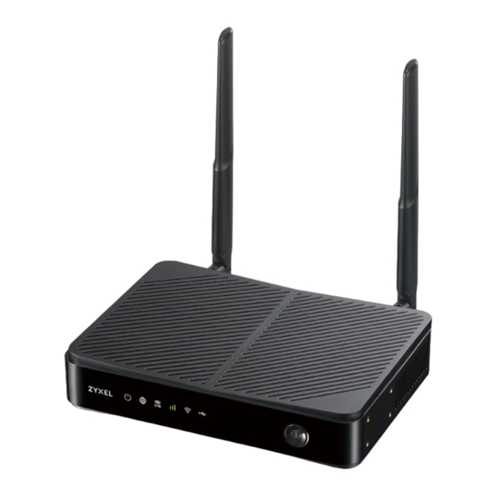
Note: Blinking (slow) means the LED blinks once per second. Blinking (fast) means the LED blinks once per 0.5 second. 2.2.1 Nebula LTE3301-PLUS Figure 6 Nebula LTE3301-PLUS LED The following are the LED descriptions for your Nebula LTE3301-PLUS. Table 3 Nebula LTE3301-PLUS LED Behavior COLOR STATUS... -
Page 27: Nebula Lte7641-M602
Chapter 2 Hardware Panels Table 3 Nebula LTE3301-PLUS LED Behavior (continued) COLOR STATUS DESCRIPTION LTE/3G White The Zyxel Device is registered and successfully connected to a 4G network. Blinking The Zyxel Device is connected to a 3G network. (slow) Blinking The Zyxel Device is trying to connect to a 3G/4G network. -
Page 28: Nebula Nr5101
Chapter 2 Hardware Panels The following are the LED descriptions for your Nebula LTE7461-M602. Table 4 Nebula LTE7461-M602 LED Behavior COLOR STATUS DESCRIPTION Blinking The Zyxel Device is booting or self-testing. The Zyxel Device encountered an error. Green Blinking The Zyxel Device is trying to connect to the Internet. The Zyxel Device is connected to the Internet. -
Page 29: Nebula Nr7101
Chapter 2 Hardware Panels Table 5 Nebula NR5101 LED Behavior (continued) COLOR STATUS DESCRIPTION Cellular Signal Green The signal strength is excellent. Strength Orange The signal strength is fair. The signal strength is poor. Blinking There is no cellular signal, or signal strength is below the poor level. -
Page 30: Nebula Fwa510
Chapter 2 Hardware Panels 2.2.5 Nebula FWA510 Figure 10 Nebula FWA510 LED The following are the LED descriptions for your Nebula FWA510. Table 7 Nebula FWA510 LED Behavior COLOR STATUS DESCRIPTION Power Green The Zyxel Device is receiving power and ready for use. Blinking The Zyxel Device is booting. -
Page 31: Nebula Fwa710
The Zyxel Device is booting. Green/ Looping Firmware upgrade is in progress. Amber/ 2.3 Panel Ports The following figures show the panel ports and buttons of the Zyxel Device. 2.3.1 Nebula LTE3301-PLUS Figure 12 Nebula LTE3301-PLUS Nebula Mobile Router User’s Guide... -
Page 32: Nebula Lte7461-M602
Chapter 2 Hardware Panels The following table describes the ports and buttons on your Nebula LTE3301-PLUS. Table 9 Nebula LTE3301-PLUS Panel Ports and Buttons LABELS DESCRIPTION ANT1-ANT2 Install the external antennas to strengthen the cellular signal. LAN/Ethernet Connect a computer to the LAN using an RJ45 cable. -
Page 33: Nebula Nr5101
Chapter 2 Hardware Panels 2.3.3 Nebula NR5101 Figure 14 Nebula NR5101 The following table describes the ports and buttons on your Nebula NR5101. Table 11 Nebula NR5101 Panel Ports and Buttons LABELS DESCRIPTION ANT1-ANT2 / Antenna Install the external antennas to strengthen the cellular signal. Note: To use the external antennas, you must set the INT/EXT switch to EXT. -
Page 34: Nebula Fwa510
Chapter 2 Hardware Panels The following table describes the ports and buttons on your Nebula NR7101. Table 12 Nebula NR7101 Panel Ports and Buttons LABELS DESCRIPTION USB (Type-C) The USB port of the Zyxel Device is used for maintenance only. Note: The USB port can only be used by qualified technicians. -
Page 35: Nebula Fwa710
Chapter 2 Hardware Panels The following table describes the ports and buttons on your Nebula FWA510. Table 13 Nebula FWA510 Ports and Buttons LABELS DESCRIPTION ANT1-ANT2/Antenna Install the external antennas to strengthen the cellular signal. Note: To use the external antennas, you must set the INT/EXT switch to EXT. The USB port of the Zyxel Device is used for file sharing. -
Page 36: Wifi/Wps Button
Make sure the power is on. Press the WiFi/WPS button (see the following table) then release it. Table 15 How to Enable WiFi MODELS WIFI BUTTON PRESS HOLD TIME Nebula LTE3301-PLUS More than 5 seconds. Nebula LTE7461-M602 Nebula NR7101 Nebula NR5101 Press for 1 second. - Page 37 Chapter 2 Hardware Panels Figure 18 Nebula LTE3301-PLUS WiFI/WPS Button Figure 19 Nebula LTE7461-M602 Figure 20 Nebula NR5101 WiFi/WPS ButtNebula NR7101 Nebula Mobile Router User’s Guide...
-
Page 38: Reset Button
The password will be reset to the default (see the Zyxel Device label) and the IP address will be reset to 192.168.1.1. Figure 23 Nebula LTE3301-PLUS Nebula Mobile Router User’s Guide... - Page 39 Chapter 2 Hardware Panels Figure 24 Nebula LTE7461-M602 Figure 25 Nebula NR5101 Figure 26 Nebula NR7101 Figure 27 Nebula FWA510 Nebula Mobile Router User’s Guide...
- Page 40 Chapter 2 Hardware Panels Figure 28 Nebula FWA710 Make sure the Zyxel Device is connected to power and the POWER LED is on. Using a thin object, press the RESET button for more than 5 seconds. Note: If you press the RESET button for less than 5 seconds, the Zyxel Device will reboot. Nebula Mobile Router User’s Guide...
-
Page 41: Web Configurator
H A P T E R Web Configurator 3.1 Overview The Web Configurator is an HTML-based management interface that allows easy system setup and management through Internet browser. Use a browser that supports HTML5, such as Microsoft Edge, Mozilla Firefox, or Google Chrome. The recommended minimum screen resolution is 1024 by 768 pixels. In order to use the Web Configurator you need to allow: •... - Page 42 Chapter 3 Web Configurator Note: The first time you enter the password, you will be asked to change it. Make sure the new password must contain at least one uppercase letter, one lowercase letter and one number. For some models, the password must contain at least one English character and one number.
- Page 43 Chapter 3 Web Configurator Figure 31 Connection Status Nebula Mobile Router User’s Guide...
-
Page 44: Web Configurator Layout
Chapter 3 Web Configurator 3.2 Web Configurator Layout Figure 32 Screen Layout As illustrated above, the main screen is divided into these parts: • A – Settings Icon (Navigation Panel and Side Bar) • B – Layout Icon • C – Main Window 3.2.1 Settings Icon Click this icon ( to see the side bar and navigation panel. - Page 45 Chapter 3 Web Configurator Figure 33 Side Bar The icons provide the following functions. Table 17 Web Configurator Icons in the Title Bar ICON DESCRIPTION Wizard: Click this icon to open screens where you can configure the Zyxel Device’s time zone and WiFi settings.
- Page 46 Chapter 3 Web Configurator Use the menu items on the navigation panel to open screens to configure Zyxel Device features. The following tables describe each menu item. Figure 34 Navigation Panel Table 18 Navigation Panel Summary LINK FUNCTION Home Use this screen to configure basic Internet access and wireless settings. This screen also shows the network status of the Zyxel Device and computers/devices connected to it.
- Page 47 Chapter 3 Web Configurator Table 18 Navigation Panel Summary (continued) LINK FUNCTION Use this screen to block or allow wireless traffic from wireless devices of Authentication certain SSIDs and MAC addresses to the Zyxel Device. Use this screen to configure and view your WPS (WiFi Protected Setup) settings.
- Page 48 Chapter 3 Web Configurator Table 18 Navigation Panel Summary (continued) LINK FUNCTION Parental Parental Control Use this screen to define time periods and days during which the Zyxel Control Device performs parental control and/or block web sites with the specific URL. Certificates Local Certificates Use this screen to view a summary list of certificates and manage...
- Page 49 Chapter 3 Web Configurator Table 18 Navigation Panel Summary (continued) LINK FUNCTION TR-069 Client TR-069 Client Use this screen to configure your Zyxel Device to be managed remotely by an Auto Configuration Server (ACS) using TR-069. Time Time Use this screen to change your Zyxel Device’s time and date. E-mail E-mail Use this screen to configure up to two mail servers and sender addresses...
- Page 50 Chapter 3 Web Configurator Figure 36 Check Icons Nebula Mobile Router User’s Guide...
-
Page 51: Quick Start
H A P T E R Quick Start 4.1 Quick Start Overview Use the Wizard screens to configure the Zyxel Device’s time zone and wireless settings. Note: See the technical reference chapters for background information on the features in this chapter. -
Page 52: Quick Start Setup - Wifi
Chapter 4 Quick Start Figure 38 Wizard – Time Zone 4.4 Quick Start Setup – WiFi Turn WiFi on or off. If you keep it on, record the WiFi Name and Password in this screen so you can configure your WiFi clients to connect to the Zyxel Device. If you want to show or hide your WiFi password, click the Eye icon ( Click the Keep 2.4G and 5G the same check box to use the same SSID for 2.4G and 5G WiFi networks. -
Page 53: Quick Start Setup - Finish
Chapter 4 Quick Start 4.5 Quick Start Setup – Finish Your Zyxel Device saves your settings and attempts to connect to the Internet. Nebula Mobile Router User’s Guide... -
Page 54: Web Interface Tutorials
H A P T E R Web Interface Tutorials 5.1 Web Interface Overview This chapter shows you how to use the Zyxel Device’s various features. • Wired Network Setup • WiFi Network Setup • Cellular Network Setup • USB Applications •... - Page 55 Chapter 5 Web Interface Tutorials In this example, configure the following information for the Ethernet connection. General Name My ETH Connection Type Ethernet Connection Mode Routing Encapsulation (Internet IPoE Type) IPv6/IPv4 Mode IPv4 Only Enter the General settings provided by your Internet service provider. Enter a Name to identify your WAN connection.
-
Page 56: Wifi Network Setup
Chapter 5 Web Interface Tutorials Go to the Network Setting > Broadband screen to view the established Ethernet connection. The new connection is displayed on the Broadband screen. 5.3 WiFi Network Setup In this example, you want to set up a WiFi network so that you can use your notebook to access the Internet. -
Page 57: Changing Security On A Wifi Network
Chapter 5 Web Interface Tutorials Figure 40 WiFi Network Setup Figure 41 Zyxel Device Configuration through WiFi Connection See the label on the Zyxel Device for the WiFi network settings and then connect manually to the Zyxel Device. Alternatively, you can set up a WiFi network using WPS. See Section 5.3.2 on page 5.3.1 Changing Security on a WiFi Network This example changes the default security settings of a WiFi network to the following:... - Page 58 Chapter 5 Web Interface Tutorials Go to the Wireless > Others screen. Set 802.11 Mode to 802.11b/g/n Mixed, and then click Apply. Nebula Mobile Router User’s Guide...
-
Page 59: Connecting To The Zyxel Device's Wifi Network Using Wps
Chapter 5 Web Interface Tutorials You can now use the WPS feature to establish a WiFi connection between your notebook and the Zyxel Device (see Section 5.3.2 on page 59). Now use the new security settings to connect to the Internet through the Zyxel Device using WiFi. - Page 60 Chapter 5 Web Interface Tutorials In Windows 10, click on the Network icon in the system tray to open the list of available WiFi networks. Locate the WiFi network of the Zyxel Device. The default WiFi network name is “Zyxel_XXXX” (2.4G) or “Zyxel_XXXX_5G”...
- Page 61 Chapter 5 Web Interface Tutorials The Zyxel Device sends the WiFi network settings to Windows using WPS. Windows displays “Getting settings from the router”. Nebula Mobile Router User’s Guide...
- Page 62 Chapter 5 Web Interface Tutorials The WiFi device is then able to connect to the WiFi network securely. 5.3.2.2 WPS PIN Configuration The WPS PIN (Personal Identification Number) method is a more secure version of WPS, used by WiFi- enabled devices such as printers. To use this connection method, you need to log into the Zyxel Device’s Web Configurator.
-
Page 63: Setting Up A Guest Network
Chapter 5 Web Interface Tutorials Within 2 minutes, enable WPS on the WiFi device. The Zyxel Device authenticates the WiFi device using the PIN, and then sends the WiFi network settings to the device using WPS. This process may take up to 2 minutes. The WiFi device is then able to connect to the WiFi network securely. - Page 64 Chapter 5 Web Interface Tutorials • Employees using the General WiFi network group will have access to the local network and the Internet. • Visitors using the Guest WiFi network group with a different SSID and password will have access to the Internet only.
- Page 65 Chapter 5 Web Interface Tutorials Go to the Network Setting > Wireless > Guest/More AP screen. Click the Modify icon to configure the second WiFi network group. On the Guest/More AP screen, click the Modify icon to configure the other Guest WiFi network group. Configure the screen using the provided parameters and click OK.
- Page 66 Chapter 5 Web Interface Tutorials Check the status of Guest in the Guest/More AP screen. A yellow bulb under Status means the SSID is active and ready for WiFi access. Nebula Mobile Router User’s Guide...
-
Page 67: Setting Up Two Guest Wifi Networks On Different Wifi Bands
Chapter 5 Web Interface Tutorials 5.3.4 Setting Up Two Guest WiFi Networks on Different WiFi Bands In this example, a company wants to create two Guest WiFi networks: one for the Guest group and the other for the VIP group as shown in the following figure. Each network will have its SSID and security mode to access the internet. - Page 68 Chapter 5 Web Interface Tutorials Go to the Wireless > Guest/More AP screen and click the Modify icon. The following screen appears. Configure the Security Mode and Password using the provided parameters and click OK. Nebula Mobile Router User’s Guide...
- Page 69 Chapter 5 Web Interface Tutorials The 2.4GHz Guest WiFi network is now configured. Go to the Wireless > General screen and set Band to 5GHz to configure the 5G Guest WiFi settings for VIP. Click OK. Nebula Mobile Router User’s Guide...
- Page 70 Chapter 5 Web Interface Tutorials Go to the Wireless > Guest/More AP screen and click the Modify icon. The following screen appears. Configure the Security Mode and Password using the provided parameters and click OK. Nebula Mobile Router User’s Guide...
- Page 71 Chapter 5 Web Interface Tutorials The 5G VIP WiFi network is now configured. Nebula Mobile Router User’s Guide...
-
Page 72: Cellular Network Setup
Chapter 5 Web Interface Tutorials 5.4 Cellular Network Setup This section shows you how to set up a cellular network. 5.4.1 Setting up a Cellular Network Connection This section gives you an example on how to connect to the Internet using over a cellular connection. Insert a SIM Card into your Zyxel Device SIM slot. - Page 73 Chapter 5 Web Interface Tutorials • APN Manual Mode: Enable this to configure your APN cellular information manually. • APN: Enter the Access Point Name (APN) provided by your ISP. You can type a name up to 30 printable ASCII characters, including spaces. •...
-
Page 74: Usb Applications
Chapter 5 Web Interface Tutorials 5.5 USB Applications This section shows you how to set up a cellular backup network, access shared folders and play files through Window Media using a USB device. 5.5.1 File Sharing This section shows you how to create a shared folder on your Zyxel Device through a USB device and allow others to access the shared folder with File Sharing services. - Page 75 Chapter 5 Web Interface Tutorials The Add New Share screen appears. Select your USB device from the Volume drop-down list box. Enter a Description name for the added share to identify the device. Click Browse and the Browse Directory screen appears. On the Browse Directory screen, select the folder that you want to add as a share.
- Page 76 Chapter 5 Web Interface Tutorials In Access Level, select Public to let the share to be accessed by all users connected to the Zyxel Device. Otherwise, select Security to let the share to be accessed by specific users to access only. Click OK to save the settings.
- Page 77 Chapter 5 Web Interface Tutorials 5.5.1.2 Accessing Your Shared Files From a Computer You can use Windows Explorer to access the USB storage devices connected to the Zyxel Device. Note: This example shows you how to use Microsoft Windows 10 to browse shared files in a share called (usb1_sda)Zoeys file.
-
Page 78: Network Security
Chapter 5 Web Interface Tutorials 5.6 Network Security This section shows you how to configure a Firewall rule, Parental Control rule, and MAC Filter rule. 5.6.1 Configuring a Firewall Rule You can enable the firewall to protect your LAN computers from malicious attacks from the Internet. Go to the Security >... - Page 79 Chapter 5 Web Interface Tutorials Use the following fields to configure and apply a new ACL (Access Control List) rule. • Filter Name: Enter a name to identify the firewall rule. • Source IP Address: Enter the IP address of the computer that initializes traffic for the application or service.
-
Page 80: Parental Control
Chapter 5 Web Interface Tutorials • Policy: Select whether to (ACCEPT, DROP, or REJECT) the packets. • Direction: Select the direction (WAN to LAN, LAN to WAN, WAN to ROUTER, or LAN to ROUTER) of the traffic to which this rule applies. Select Enable Rate Limit to activate the rules you created. - Page 81 Chapter 5 Web Interface Tutorials Add New PCP Screen Go to Parental Control > Add New PCP. Under General: Select Enable to enable the rule you are configuring. Enter the Parental Control Profile Name given in the above parameter. Select an user this rule applies to in Home Network User, then click Add. You will see the MAC address of the user you just select in Rule List.
- Page 82 Chapter 5 Web Interface Tutorials Use the parameter give above to configure the time settings of your schedule. Under Network Service: In Network Service Setting, select Block. Click Add New Service, then use the parameter given above to configure settings for the Internet service you are blocking.
- Page 83 Chapter 5 Web Interface Tutorials This example shows you how to block an user from accessing the Internet during time for studying. Use the parameter below to configure a schedule rule. PROFILE NAME START BLOCKING END BLOCKING REPEAT ON Study 8:00 am 11:00 am from Monday to Friday...
-
Page 84: Configuring A Mac Address Filter For Wired Lan Connections
Chapter 5 Web Interface Tutorials 5.6.3 Configuring a MAC Address Filter for Wired LAN Connections You can use a MAC address filter to exclusively allow or permanently block someone from the wired LAN network. This example shows that computer B is not allowed access to the wired LAN network. Figure 42 Configure a MAC Address Filter Example Nebula Mobile Router User’s Guide... -
Page 85: Device Maintenance
Chapter 5 Web Interface Tutorials Go to the Security > MAC Filter > MAC Filter screen. Under MAC Address Filter, select Enable. Click Add New Rule to add a new entry. Select Active, and then enter the Host Name and MAC Address of computer B. -
Page 86: Backing Up The Device Configuration
Chapter 5 Web Interface Tutorials Go to the Maintenance > Firmware Upgrade screen. Click Browse/Choose File and select the file with a ".bin" extension to upload. Click Upload. This process may take up to 2 minutes to finish. After 2 minutes, log in again and check your new firmware version in the Connection Status screen. -
Page 87: Restoring The Device Configuration
Chapter 5 Web Interface Tutorials 5.7.3 Restoring the Device Configuration This section shows you how to restore a previously-saved configuration file from your computer to your Zyxel Device. Go to the Maintenance > Backup/Restore screen. Under Restore Configuration, click Browse/Choose File, and then select the configuration file that you want to upload. - Page 88 Chapter 5 Web Interface Tutorials The Zyxel Device automatically restarts after the configuration file is successfully uploaded. Wait for one minute before logging into the Zyxel Device again. Go to the Connection Status page to check the firmware version after the reboot. Nebula Mobile Router User’s Guide...
-
Page 89: Technical Reference
Technical Reference Nebula Mobile Router User’s Guide... -
Page 90: Connection Status
H A P T E R Connection Status 6.1 Connection Status Overview After you log into the Web Configurator, the Connection Status screen appears. You can configure basic Internet access and wireless settings in this screen. It also shows the network status of the Zyxel Device and computers or devices connected to it. -
Page 91: Icon And Device Name
Chapter 6 Connection Status 6.1.2 Icon and Device Name Select an icon and/or enter a name in the Device Name field for a connected device. Click to enable ) Internet Blocking (or Active) for a connected WiFi client. Click Save to save your changes. Figure 45 Connectivity: Edit 6.1.3 System Info Use this screen to view the basic system information of the Zyxel Device. - Page 92 Chapter 6 Connection Status Figure 47 System Info: Detailed Information Each field is described in the following table. Table 20 System Info: Detailed Information LABEL DESCRIPTION Host Name This field displays the Zyxel Device system name. It is used for identification. Model Name This shows the model number of your Zyxel Device.
-
Page 93: Cellular Info
Chapter 6 Connection Status Table 20 System Info: Detailed Information (continued) LABEL DESCRIPTION Primary DNSv6 This field displays the first DNS server IPv6 address assigned by the ISP. server Secondary This field displays the second DNS server IPv6 address assigned by the ISP. DNSv6 server LAN Information IP Address... - Page 94 Chapter 6 Connection Status Figure 48 Cellular Info Click the Arrow icon ( ) to view the more information on the cellular connection. Figure 49 Cellular Info: Detailed Information Note: The fields in the screen may slightly differ based on the Access Technology your Zyxel Device supports.
- Page 95 Chapter 6 Connection Status Table 21 Cellular Info: Detailed Information (continued) LABEL DESCRIPTION SIM Status SIM Card Status This displays the SIM card status: None - the Zyxel Device does not detect that there is a SIM card inserted. Waiting SIM Available - the SIM card is detected but not available yet. Available - the SIM card could either have or do not have PIN code security.
- Page 96 Chapter 6 Connection Status Table 21 Cellular Info: Detailed Information (continued) LABEL DESCRIPTION Enable This shows if GNSS is enabled. Note: This can only be configured by a qualified service technician. Scan This shows Enable if Scan OnBoot is enabled, so that GNSS runs automatically after the Zyxel OnBoot Device is turned on.
- Page 97 Chapter 6 Connection Status Table 21 Cellular Info: Detailed Information (continued) LABEL DESCRIPTION Cell ID This shows the cell ID, which is a unique number used to identify the Base Transceiver Station to which the Zyxel Device is connecting. The value depends on the type of the mobile network (such as LTE, UMTS, GSM) to which the Zyxel Device is connecting: •...
- Page 98 Chapter 6 Connection Status Table 21 Cellular Info: Detailed Information (continued) LABEL DESCRIPTION EcNo This displays the ratio (in dB) of the received energy per chip and the interference level. The measured EcNo is in 0.1 dB and is received in the downlink pilot channel. An undetectable signal is indicated by the lower limit, example –240 dB.
-
Page 99: Cloud Control Status
Chapter 6 Connection Status Table 21 Cellular Info: Detailed Information (continued) LABEL DESCRIPTION Physical Cell ID This displays the Physical Cell ID (PCI) of the SCC. UL Bandwidth This shows the uplink cellular channel bandwidth from the Zyxel Device to the base station. (MHz) According to 3GPP specifications, the bandwidths defined by the standard are 1.4, 3, 5, 10, 15, and 20 MHz. -
Page 100: Wifi Settings
Chapter 6 Connection Status Each field is described in the following table. Table 22 Cloud Control Status LABEL DESCRIPTION Nebula Discovery Enable this to have the Zyxel Device connect to the NCC and change to the NCC management mode if the Zyxel Device is connected to the Internet and has been registered on the NCC. - Page 101 Chapter 6 Connection Status Click the Arrow icon ( ) to configure the SSIDs and/or passwords for your main wireless networks. Click the Eye icon ( ) to display the characters as you enter the WiFi Password. Scanning the QR code is an alternative way to connect your WiFi client to the WiFi network. Select Keep 2.4G and 5G the same to use the same SSID for 2.4 GHz and 5 GHz bands.
-
Page 102: Guest Wifi Settings
Chapter 6 Connection Status 6.2 Guest WiFi Settings Use this screen to enable or disable the guest 2.4 GHz and/or 5 GHz wireless networks. When the switch goes to the right ( ), the function is enabled. Otherwise, it is not. You can check their SSIDs (WiFi network name) and passwords from this screen. -
Page 103: Lan
Chapter 6 Connection Status Figure 56 Guest WiFi Settings: Different SSIDs Each field is described in the following table. Table 24 WiFi Settings: Configuration LABEL DESCRIPTION 2.4G/5G WiFi Click this switch to enable or disable the 2.4 GHz and/or 5 GHz wireless networks. When the switch goes to the right , the function is enabled. - Page 104 Chapter 6 Connection Status Figure 57 LAN Click the Arrow icon ( ) to configure the LAN IP settings and DHCP setting for your Zyxel Device. Figure 58 LAN Setup Each field is described in the following table. Table 25 LAN Setup LABEL DESCRIPTION Group Name...
- Page 105 Chapter 6 Connection Status Table 25 LAN Setup (continued) LABEL DESCRIPTION Ending IP This field specifies the last of the contiguous addresses in the IP address pool. Address DHCP Server State DHCP Server This is the period of time a DHCP-assigned address is valid, before it expires. Lease Time When a client connects to the Zyxel Device, DHCP automatically assigns the client an IP addresses from the IP address pool.
-
Page 106: Broadband
H A P T E R Broadband 7.1 Broadband Overview This chapter discusses the Zyxel Device’s Broadband screens. Use these screens to configure your Zyxel Device for Internet access. A WAN (Wide Area Network) connection is an outside connection to another network or the Internet. It connects your private networks, such as a LAN (Local Area Network) and other networks, so that a computer in one location can communicate with computers in other locations. -
Page 107: What You Need To Know
Chapter 7 Broadband • Use the Cellular Lock screens to configure the base station you choose to connect to (Section 7.11 on page 127). • Use the Cellular SMS screen to send and receive SMS messages from the Zyxel Device (Section 7.12 on page 129). -
Page 108: Before You Begin
Chapter 7 Broadband Figure 60 464XLAT 7.1.3 Before You Begin You may need to know your Internet access settings such as APN, WAN IP address and SIM card’s PIN code if the INTERNET light on your Zyxel Device is off. Get this information from your service provider. 7.2 Broadband Use this screen to change your Zyxel Device’s Internet access settings. -
Page 109: Add Or Edit Internet Connection
Chapter 7 Broadband Figure 61 Network Setting > Broadband The following table describes the labels in this screen. Table 27 Network Setting > Broadband LABEL DESCRIPTION This is the index number of the entry. Name This is the service name of the connection. Type This shows whether it is a cellular or Ethernet connection. - Page 110 Chapter 7 Broadband Figure 62 Network Setting > Broadband > Add or Edit New WAN Interface The following table describes the labels in this screen. Table 28 Network Setting > Broadband > Add or Edit New WAN Interface LABEL DESCRIPTION General Click this switch to enable or disable the interface.
- Page 111 Chapter 7 Broadband Table 28 Network Setting > Broadband > Add or Edit New WAN Interface (continued) LABEL DESCRIPTION IPv4/IPv6 Mode This shows IPv4 IPv6 DualStack. IPv4 IPv6 DualStack allows the Zyxel Device to run IPv4 and IPv6 at the same time. VLAN Click this switch to enable or disable VLAN on this WAN interface.
- Page 112 Chapter 7 Broadband Table 28 Network Setting > Broadband > Add or Edit New WAN Interface (continued) LABEL DESCRIPTION DHCPC Options Request Options Select Option 43 to have the Zyxel Device get vendor specific information from DHCP packets sent from the DHCP server. Select Option 120 to have the Zyxel Device get an IP address or a fully-qualified domain name of a SIP server from DHCP packets sent from the DHCP server.
-
Page 113: Ethernet Wan
Chapter 7 Broadband Table 28 Network Setting > Broadband > Add or Edit New WAN Interface (continued) LABEL DESCRIPTION 464XLAT Enable this to have the Zyxel Device translate outgoing IPv4 packets to IPv6 packets. Use this function if you want to use IPv4 devices and services when your ISP provides an IPv6-only mobile network. -
Page 114: Cellular Wan
Chapter 7 Broadband 7.4 Cellular WAN Click Network Setting > Broadband > Cellular WAN to display the following screen. Use this screen to enable data roaming and network monitoring when the Zyxel Device cannot ping a base station. Note: Roaming charges may apply when Data Roaming is enabled. Figure 64 Network Setting >... -
Page 115: Cellular Apn
Chapter 7 Broadband Table 29 Network Setting > Broadband > Cellular WAN (continued) LABEL DESCRIPTION Network Use this field to allow Zyxel Device to try reconnecting to the base station if the cellular Monitoring connection is lost. After the third try, the Zyxel Device will reboot to try to reconnect with the base station. -
Page 116: Edit Cellular Apn1/Apn2
Chapter 7 Broadband Note: This feature is only available on certain models. Figure 65 Network Setting > Broadband > Cellular APN The following table describes the labels in this screen. Table 30 Network Setting > Broadband > Cellular APN LABEL DESCRIPTION APN Settings This is the number of an individual APN. - Page 117 Chapter 7 Broadband Figure 66 Network Setting > Broadband > Cellular APN > Edit APN The following table describes the fields in this screen. Table 31 Network Setting > Broadband > Cellular APN > Edit APN LABEL DESCRIPTION Enable Click this to enable ( ) the APN on the Zyxel Device APN Manual Mode Disable this to have the Zyxel Device configure the APN (Access Point Name) of a...
-
Page 118: Using Separate Apns For Data And Management Traffic
Chapter 7 Broadband Table 31 Network Setting > Broadband > Cellular APN > Edit APN LABEL DESCRIPTION Authentication Type Select the type of authentication method peers use to connect to the Zyxel Device in cellular connections. In Password Authentication Protocol (PAP) peers identify themselves with a user name and password. - Page 119 Chapter 7 Broadband Go to Maintenance > Remote Management > MGMT Services. Set WAN Interface used for services to Multi_WAN, and then select Cellular WAN 2. Nebula Mobile Router User’s Guide...
-
Page 120: Cellular Sim Configuration
Chapter 7 Broadband Go to Maintenance > TR-069 Client. Set WAN Interface used by TR-069 Client to Multi_WAN, and then select Cellular WAN 2. 7.6 Cellular SIM Configuration Use this screen to enter a PIN for your SIM card, in order to prevent others from using it. Entering the wrong PIN code 3 consecutive times locks the SIM card, after which you need a PUK (Personal Unlocking Key) from the service provider to unlock it. - Page 121 Chapter 7 Broadband Click Network Setting > Broadband > Cellular SIM. The following screen opens. Figure 67 Network Setting > Broadband > Cellular SIM Note: The PIN is automatically saved in the Zyxel Device. Entering the wrong PIN exceeding a set number of times will lock the SIM card. The following table describes the fields in this screen.
-
Page 122: Cellular Dual Sim
Chapter 7 Broadband 7.7 Cellular Dual SIM Some Zyxel Devices support dual SIM card slots for cellular backup (failover) to ensure Internet connectivity. To see if your Zyxel Device supports Cellular Dual SIM, see Section 1.1.1 on page 17. Use this screen to set the main SIM card slot and configure cellular backup with dual SIM cards. -
Page 123: Cellular Band Configuration
Chapter 7 Broadband 7.8 Cellular Band Configuration Either select Auto to have the Zyxel Device connect to an available network using the default settings on the SIM card or select the type of the network (NR5G, 4G, 3G) to which you want the Zyxel Device to connect. -
Page 124: Cellular Plmn Configuration
Chapter 7 Broadband 7.9 Cellular PLMN Configuration Each service provider has its own unique Public Land Mobile Network (PLMN) number. Either select PLMN Auto Selection to have the Zyxel Device connect to the service provider using the default settings on the SIM card, or manually view available PLMNs and select your service provider. - Page 125 Chapter 7 Broadband Figure 72 Network Setting > Broadband > Cellular PLMN > PLMN Management The following table describes the labels in this screen. Table 36 Network Setting > Broadband > Cellular PLMN > PLMN Management LABEL DESCRIPTION Click the radio button so the Zyxel Device connects to this ISP. Status This shows Current to show the ISP the Zyxel Device is currently connected to.
-
Page 126: Cellular Ip Passthrough
Chapter 7 Broadband 7.10 Cellular IP Passthrough Enable IP Passthrough to allow Internet traffic to go to a LAN computer behind the Zyxel Device without going through NAT. Click Network Setting > Broadband > Cellular IP Passthrough to display the following screen. Note: This screen is not available when the fourth LAN port acts as an Ethernet WAN port. -
Page 127: Cellular Lock Overview
Chapter 7 Broadband The following table describes the fields in this screen. Table 37 Network Setting > Broadband > Cellular IP Passthrough LABEL DESCRIPTION IP Passthrough Management IP Passthrough IP Passthrough allows a LAN computer on the local network of the Zyxel Device to have access to web services using the public IP address. -
Page 128: Cellular Lock (5G)
Chapter 7 Broadband Figure 75 Network Setting > Broadband > Cellular Lock (LTE) The following table describes the fields in this screen. Table 38 Network Setting > Broadband > Cellular Lock (LTE) LABEL DESCRIPTION LTE(4G) Lock Management PCI Lock Click the switch button (to the right) to enable PCI (Physical Cell Identifier) Lock on base stations when the Zyxel Device has 4G LTE connections. -
Page 129: Cellular Sms
Chapter 7 Broadband Figure 76 Network Setting > Broadband > Cellular Lock (5G) The following table describes the fields in this screen. Table 39 Network Setting > Broadband > Cellular Lock (5G) LABEL DESCRIPTION NR(5G) Lock Management PCI_Enable Click the switch button (to the right) to enable PCI (Physical Cell Identifier) Lock on a base station when the Zyxel Device has a 5G NR connection. -
Page 130: Send New Message Screen
Chapter 7 Broadband Figure 77 Network Setting > Broadband > Cellular SMS The following table describes the fields in this screen. Table 40 Network Setting > Broadband > LABEL DESCRIPTION Add New Message Click this button to open the Send New Message screen and send an SMS message from the Zyxel Device. - Page 131 Chapter 7 Broadband Figure 78 Network Setting > Broadband > Cellular SMS > Send New Message The following table describes the fields in this screen. Table 41 Network Setting > Broadband > Cellular SMS > LABEL DESCRIPTION Character Set Select whether you want to send the SMS message using GSM-7 encoding or unicode.
-
Page 132: Wireless
H A P T E R Wireless 8.1 Wireless Overview This chapter describes the Zyxel Device’s Network Setting > Wireless screens. Use these screens to set up your Zyxel Device’s WiFi network and security settings. 8.1.1 What You Can Do in this Chapter This section describes the Zyxel Device’s Wireless screens. -
Page 133: Wireless General Settings
Chapter 8 Wireless WiFi6 / IEEE 802.11ax WiFi6 is backwards compatible with IEEE 802.11a/b/g/n/ac and is most suitable in areas with a high concentration of users. WiFi6 devices support Target Wakeup Time (TWT) allowing them to automatically power down when they are inactive. The following table displays the comparison of the different WiFi standards. - Page 134 Chapter 8 Wireless Figure 79 Network Setting > Wireless > General The following table describes the general WiFi labels in this screen. Table 43 Network Setting > Wireless > General LABEL DESCRIPTION Wireless Wireless Select Keep the same settings for 2.4G and 5G wireless networks and the 2.4 GHz and 5 GHz wireless networks will use the same SSID and wireless security settings.
- Page 135 Chapter 8 Wireless Table 43 Network Setting > Wireless > General (continued) LABEL DESCRIPTION Wireless/WiFi Network Setup Band This shows the wireless band which this radio profile is using. 2.4GHz is the frequency used by IEEE 802.11b/g/n/ax WiFi clients while 5GHz is used by IEEE 802.11a/n/ac/ax WiFi clients. Wireless/WiFi Click this switch to enable or disable WiFi in this field.
-
Page 136: No Security
Chapter 8 Wireless Table 43 Network Setting > Wireless > General (continued) LABEL DESCRIPTION Cancel Click Cancel to restore your previously saved settings. Apply Click Apply to save your changes. 8.2.1 No Security Select No Security to allow wireless stations to communicate with the access points without any data encryption or authentication. - Page 137 Chapter 8 Wireless Figure 81 Wireless > General: More Secure: WPA3-SAE/WPA2-PSK The following table describes the labels in this screen. Table 45 Wireless > General: More Secure: WPA3-SAE/WPA2-PSK LABEL DESCRIPTION Security Level Select More Secure to enable data encryption. Security Mode Select a security mode from the drop-down list box.
-
Page 138: Guest/More Ap Screen
Chapter 8 Wireless 8.3 Guest/More AP Screen Use this screen to configure a guest wireless network that allows access to the Internet through the Zyxel Device. You can use one access point to provide several BSSs simultaneously. You can then assign varying security types to different SSIDs. - Page 139 Chapter 8 Wireless Note: If upstream/downstream bandwidth is empty, the Zyxel Device sets the value automatically. Setting a maximum upstream/downstream bandwidth will significantly decrease wireless performance. Click the Edit icon next to an SSID in the Guest/More AP screen. The following screen displays. Figure 83 Network Setting >...
- Page 140 Chapter 8 Wireless Table 48 Network Setting > Wireless > Guest/More AP > Edit (continued) LABEL DESCRIPTION WiFi/Wireless Network Settings WiFi/Wireless The SSID (Service Set IDentity) identifies the service set with which a wireless device is associated. Network Name Wireless devices associating to the access point (AP) must have the same SSID. Enter a descriptive name (up to 32 English keyboard characters) for the wireless LAN.
-
Page 141: Mac Authentication
Chapter 8 Wireless Table 48 Network Setting > Wireless > Guest/More AP > Edit (continued) LABEL DESCRIPTION Encryption Select the encryption type (AES or TKIP+AES) for data encryption. Select AES if your WiFi clients can all use AES. Select TKIP+AES to allow the WiFi clients to use either TKIP or AES. Not all models support the TKIP+AES option. -
Page 142: Wps
Chapter 8 Wireless Table 49 Network Setting > Wireless > MAC Authentication (continued) LABEL DESCRIPTION MAC Restrict Define the filter action for the list of MAC addresses in the MAC Address table. Mode Select Disable to turn off MAC filtering. Select Deny to block access to the Zyxel Device. - Page 143 Chapter 8 Wireless Note: The WPS switch is unavailable if the wireless LAN is disabled. If WPS is enabled, UPnP will automatically be turned on. Click Network Setting > Wireless > WPS. The following screen displays. Click this switch and it will turn blue. Click Apply to activate the WPS function.
-
Page 144: Wmm
Chapter 8 Wireless Table 50 Network Setting > Wireless > WPS (continued) LABEL DESCRIPTION Register Enter the PIN of the device that you are setting up a WPS connection with and click Register to authenticate and add the WiFi device to your WiFi network. You can find the PIN either on the outside of the device, or by checking the device’s settings. -
Page 145: Others Screen
Chapter 8 Wireless Note: APSD only affects SSID1. For SSID2-SSID4, APSD is always enabled. The following table describes the labels in this screen. Table 51 Network Setting > Wireless > WMM LABEL DESCRIPTION WiFi WMM of SSID Select On to have the Zyxel Device automatically give the network (SSIDx) a priority level WiFi according to the ToS value in the IP header of packets it sends. - Page 146 Chapter 8 Wireless Figure 87 Network Setting > Wireless > Others The following table describes the labels in this screen. Table 52 Network Setting > Wireless > Others LABEL DESCRIPTION RTS/CTS Data with its frame size larger than this value will perform the RTS (Request To Send)/CTS (Clear Threshold To Send) handshake.
- Page 147 Chapter 8 Wireless Table 52 Network Setting > Wireless > Others (continued) LABEL DESCRIPTION 802.11 Mode For 2.4 GHz frequency WiFi devices: • Select 802.11b Only to allow only IEEE 802.11b compliant WiFi devices to associate with the Zyxel Device. •...
-
Page 148: Wlan Scheduler
Chapter 8 Wireless 8.8 WLAN Scheduler Use the WLAN Scheduler screen to create rules to schedule the times to permit Internet traffic from each wireless network interfaces. Select a specific time and day of a week for scheduling. You can also create a rule to automatically switch off all the WLAN together. -
Page 149: Add Or Edit Rules
Chapter 8 Wireless Note: If you enable a rule for a specific SSID, you will not be able to connect to other wireless networks. 8.8.1 Add or Edit Rules Click Add New Rule in the WLAN Scheduler screen, or click the Edit icon next to a scheduling rule, and the following screen displays. -
Page 150: Channel Status
Chapter 8 Wireless 8.9 Channel Status Use this screen to scan for WiFi channel noise and view the results. Click Scan to start, and then view the results in the Channel Scan Result section. The value on each channel number indicates the number of Access Points (AP) using that channel. -
Page 151: Technical Reference
Chapter 8 Wireless Table 55 Network Setting > Wireless > Channel Status (continued) LABEL DESCRIPTION Scan wireless Click the Scan button to scan WiFi channels. LAN Channels Channel Scan This displays the results of the channel scan. Result The blue bar displays the number of access points (AP count) in the WiFi channel. The orange bar displays the WiFi channel that the Zyxel Device is now using. - Page 152 Chapter 8 Wireless Figure 91 Example of a WiFi Network The WiFi network is the part in the blue circle. In this WiFi network, devices A and B use the access point (AP) to interact with the other devices (such as the printer) or with the Internet. Your Zyxel Device is the Every WiFi network must follow these basic guidelines.
-
Page 153: Additional Wireless Terms
Chapter 8 Wireless 8.10.2 Additional Wireless Terms The following table describes some WiFi network terms and acronyms used in the Zyxel Device’s Web Configurator. Table 56 Additional WiFi Terms TERM DESCRIPTION RTS/CTS Threshold In a WiFi network which covers a large area, WiFi devices are sometimes not aware of each other’s presence. -
Page 154: Signal Problems
Chapter 8 Wireless Vanishing Point (which you know was made in 1971) you could use “70dodchal71vanpoi” as your security key. The following sections introduce different types of WiFi security you can set up in the WiFi network. 8.10.3.1 SSID Normally, the Zyxel Device acts like a beacon and regularly broadcasts the SSID in the area. You can hide the SSID instead, in which case the Zyxel Device does not broadcast the SSID. -
Page 155: Bss
Chapter 8 Wireless coincidental emitters such as electric motors or microwaves. Problems with absorption occur when physical objects (such as thick walls) are between the two radios, muffling the signal. 8.10.5 BSS A Basic Service Set (BSS) exists when all communications between wireless stations go through one access point (AP). -
Page 156: Wifi Protected Setup (Wps)
Chapter 8 Wireless Use the dynamic setting to automatically use short preamble when all WiFi devices on the network support it, otherwise the Zyxel Device uses long preamble. Note: The devices MUST use the same preamble mode in order to communicate. WiFi 8.10.7 WiFi Protected Setup (WPS) Your Zyxel Device supports WiFi Protected Setup (WPS), which is an easy way to set up a secure WiFi... - Page 157 Chapter 8 Wireless WPS in range of each other. However, you need to log into the configuration interfaces of both devices to use the PIN method. When you use the PIN method, you must enter the PIN from one device (usually the WiFi client) into the second device (usually the Access Point or wireless router).
- Page 158 Chapter 8 Wireless Figure 93 Example WPS Process: PIN Method 8.10.7.3 How WPS Works When two WPS-enabled devices connect, each device must assume a specific role. One device acts as the registrar (the device that supplies network and security settings) and the other device acts as the enrollee (the device that receives network and security settings.
- Page 159 Chapter 8 Wireless Figure 94 How WPS Works The roles of registrar and enrollee last only as long as the WPS setup process is active (2 minutes). The next time you use WPS, a different device can be the registrar if necessary. The WPS connection process is like a handshake;...
- Page 160 Chapter 8 Wireless Figure 95 WPS: Example Network Step 1 In step 2, you add another WiFi client to the network. You know that Client 1 supports registrar mode, but it is better to use AP1 for the WPS handshake with the new client since you must connect to the access point anyway in order to use the network.
- Page 161 Chapter 8 Wireless Figure 97 WPS: Example Network Step 3 8.10.7.5 Limitations of WPS WPS has some limitations of which you should be aware. • When you use WPS, it works between two devices only. You cannot enroll multiple devices simultaneously, you must enroll one after the other.
-
Page 162: Home Networking
H A P T E R Home Networking 9.1 Home Networking Overview A Local Area Network (LAN) is a shared communication system to which many computers are attached. A LAN is usually located in one immediate area such as a building or floor of a building. The LAN screens can help you configure a LAN DHCP server and manage IP addresses. - Page 163 Chapter 9 Home Networking DHCP DHCP (Dynamic Host Configuration Protocol) allows clients to obtain TCP/IP configuration at start-up from a server. This Zyxel Device has a built-in DHCP server capability that assigns IP addresses and DNS servers to systems that support DHCP client capability. DNS (Domain Name System) maps a domain name to its corresponding IP address and vice versa.
-
Page 164: Before You Begin
Chapter 9 Home Networking All UPnP-enabled devices may communicate freely with each other without additional configuration. Disable UPnP if this is not your intention. UPnP and Zyxel Zyxel has achieved UPnP certification from the Universal Plug and Play Forum UPnP™ Implementers Corp. - Page 165 Chapter 9 Home Networking Figure 99 Network Setting > Home Networking > LAN Setup Nebula Mobile Router User’s Guide...
- Page 166 Chapter 9 Home Networking Figure 100 Network Setting > Home Networking > LAN Setup (continued) The following table describes the fields in this screen. Table 57 Network Setting > Home Networking > LAN Setup LABEL DESCRIPTION Interface Group Group Name This displays the name of the group that your Zyxel Device belongs to.
- Page 167 Chapter 9 Home Networking Table 57 Network Setting > Home Networking > LAN Setup (continued) LABEL DESCRIPTION IP Address Enter the IPv4 IP address of the actual remote DHCP server in this field. IP Addressing Values The IP Addressing Values fields appear only when you select Enable in the DHCP field. Beginning IP This field specifies the first of the contiguous addresses in the IP address pool.
- Page 168 Chapter 9 Home Networking Table 57 Network Setting > Home Networking > LAN Setup (continued) LABEL DESCRIPTION LAN Global Select EU 64 to have the Zyxel Device generate an interface ID using the EU -64 format for its Identifier Type global address.
-
Page 169: Static Dhcp
Chapter 9 Home Networking Table 57 Network Setting > Home Networking > LAN Setup (continued) LABEL DESCRIPTION DNS Query Scenario Select how the Zyxel Device handles clients’ DNS information requests. IPv4/IPv6 DNS Server: The Zyxel Device forwards the requests to both the IPv4 and IPv6 DNS servers and sends clients the first DNS information it receives. - Page 170 Chapter 9 Home Networking The following table describes the labels in this screen. Table 58 Network Setting > Home Networking > Static DHCP LABEL DESCRIPTION Static DHCP Click this to configure a static DHCP entry. Configuration This is the index number of the entry. Status This field displays whether the client is connected to the Zyxel Device.
-
Page 171: Upnp
Chapter 9 Home Networking Table 59 Network Setting > Home Networking > Static DHCP: Static DHCP Configuration (continued) LABEL DESCRIPTION IP Address Enter the IP address that you want to assign to the computer on your LAN with the MAC address that you will also specify if you select Manual Input in the previous field. -
Page 172: Custom Dhcp
Chapter 9 Home Networking The following table describes the labels in this screen. Table 60 Network Settings > Home Networking > UPnP LABEL DESCRIPTION UPnP State UPnP Select Enable to activate UPnP. Be aware that anyone could use a UPnP application to open the Web Configurator's login screen without entering the Zyxel Device's IP address (although you must still enter the password to access the Web Configurator). -
Page 173: Custom Dhcp Configuration
Chapter 9 Home Networking The following table describes the labels in this screen. Table 61 Network Settings > Home Networking > Custom DHCP LABEL DESCRIPTION Custom DHCP Click this to add a DHCP option you want to sent to your DHCP clients. Configuration This field displays the index number of the entry. -
Page 174: Technical Reference
Chapter 9 Home Networking Table 62 Network Settings > Home Networking > Custom DHCP (continued) LABEL DESCRIPTION Service Name Select an interface group from the drop-down list. The Zyxel Device will add this DHCP option to DHCP packets sent on the selected service interface group. You can configure interface groups in the Network Setting >... -
Page 175: Lan Tcp/Ip
Chapter 9 Home Networking • Some ISPs choose to disseminate the DNS server addresses using the DNS server extensions of IPCP (IP Control Protocol) after the connection is up. If your ISP did not give you explicit DNS servers, chances are the DNS servers are conveyed through IPCP negotiation. -
Page 176: Turn On Upnp In Windows 10 Example
Chapter 9 Home Networking You can obtain your IP address from the IANA, from an ISP or it can be assigned from a private network. If you belong to a small organization and your Internet access is through an ISP, the ISP can provide you with the Internet addresses for your local networks. - Page 177 Chapter 9 Home Networking Click Change advanced sharing settings. Under Domain, select Turn on network discovery and click Save Changes. Network discovery allows your computer to find other computers and devices on the network and other computers on the network to find your computer.
-
Page 178: Auto-Discover Your Upnp-Enabled Network Device
Chapter 9 Home Networking 9.7.1 Auto-discover Your UPnP-enabled Network Device Before you follow these steps, make sure you already have UPnP activated on the Zyxel Device and in your computer. Make sure your computer is connected to the LAN port of the Zyxel Device. Open File Explorer and click Network. - Page 179 Chapter 9 Home Networking Figure 106 Network Connections In the Internet Connection Properties window, click Settings to see port mappings. Figure 107 Internet Connection Properties You may edit or delete the port mappings or click Add to manually add port mappings. Nebula Mobile Router User’s Guide...
- Page 180 Chapter 9 Home Networking Figure 108 Internet Connection Properties: Advanced Settings Figure 109 Internet Connection Properties: Advanced Settings: Add Note: When the UPnP-enabled device is disconnected from your computer, all port mappings will be deleted automatically. Click OK. Check the network icon on the system tray to see your Internet connection status. Figure 110 System Tray Icon To see more details about your current Internet connection status, right click the network icon in the system tray and click Open Network &...
-
Page 181: Web Configurator Easy Access In Windows 10
Chapter 9 Home Networking Figure 111 Internet Connection Status 9.8 Web Configurator Easy Access in Windows 10 Follow the steps below to access the Web Configurator. Open File Explorer. Click Network. Nebula Mobile Router User’s Guide... - Page 182 Chapter 9 Home Networking Figure 112 Network Connections An icon with the description for each UPnP-enabled device displays under Network Infrastructure. Right-click the icon for your Zyxel Device and select View device webpage. The Web Configurator login screen displays. Figure 113 Network Connections: Network Infrastructure Right-click the icon for your Zyxel Device and select Properties.
- Page 183 Chapter 9 Home Networking Figure 114 Network Connections: Network Infrastructure: Properties: Example Nebula Mobile Router User’s Guide...
-
Page 184: Routing
H A P T E R Routing 10.1 Routing Overview The Zyxel Device usually uses the default gateway to route outbound traffic from computers on the LAN to the Internet. To have the Zyxel Device send data to devices not reachable through the default gateway, use static routes. -
Page 185: Add Or Edit Static Route
Chapter 10 Routing Figure 116 Network Setting > Routing > Static Route The following table describes the labels in this screen. Table 63 Network Setting > Routing > Static Route LABEL DESCRIPTION Add New Static Click this to set up a new static route on the Zyxel Device. Route This is the number of an individual static route. - Page 186 Chapter 10 Routing Figure 117 Network Setting > Routing > Static Route > Add New Static Route The following table describes the labels in this screen. Table 64 Network Setting > Routing > Static Route > Add New Static Route LABEL DESCRIPTION Active...
- Page 187 Chapter 10 Routing You need to specify a static routing rule on the Zyxel Device to specify R as the router in charge of forwarding traffic to N2. In this case, the Zyxel Device routes traffic from A to R and then R routes the traffic to B.
- Page 188 Chapter 10 Routing Table 65 IP Settings in this Tutorial (continued) DEVICE / COMPUTER IP ADDRESS 192.168.1.34 R’s N1 192.168.1.253 R’s N2 192.168.10.2 192.168.10.33 To configure a static route to route traffic from N1 to N2: Log into the Zyxel Device’s Web Configurator in advanced mode. Click Network Setting >...
-
Page 189: Dns Route
Chapter 10 Routing 10.3 DNS Route Use this screen to view and configure DNS routes on the Zyxel Device. A DNS route entry defines a policy for the Zyxel Device to forward a particular DNS query to a specific WAN interface. Click Network Setting >... -
Page 190: Add Or Edit Dns Route
Chapter 10 Routing Table 66 Network Setting > Routing > DNS Route (continued) LABEL DESCRIPTION Subnet Mask This parameter specifies the IP network subnet mask. Modify Click the Edit icon to configure a DNS route on the Zyxel Device. Click the Delete icon to remove a DNS route from the Zyxel Device. 10.3.1 Add or Edit DNS Route You can manually add the Zyxel Device’s DNS route entry. -
Page 191: Add Or Edit Policy Route
Chapter 10 Routing through specific connections or distribute traffic across multiple paths for load sharing. Policy-based routing is applied to outgoing packets before the default routing rules are applied. The Policy Route screen let you view and configure routing policies on the Zyxel Device. Click Network Setting >... - Page 192 Chapter 10 Routing Figure 121 Network Setting > Routing > Policy Route: Add or Edit The following table describes the labels in this screen. Table 69 Network Setting > Routing > Policy Route: Add or Edit LABEL DESCRIPTION Active Click this to enable (turns blue) activation of the policy route. Otherwise, click to disable (turns gray).
-
Page 193: Rip Overview
Chapter 10 Routing 10.5 RIP Overview Routing Information Protocol (RIP, RFC 1058 and RFC 1389) allows the Zyxel Device to exchange routing information with other routers. To activate RIP for the WAN interface, select the supported RIP version and operation. 10.5.1 RIP Click Network Setting >... -
Page 194: Network Address Translation (Nat)
H A P T E R Network Address Translation (NAT) 11.1 NAT Overview NAT (Network Address Translation – NAT, RFC 1631) is the translation of the IP address of a host in a packet, for example, the source address of an outgoing packet, used within one network to a different IP address known within another network. -
Page 195: Port Forwarding
Chapter 11 Network Address Translation (NAT) Port Forwarding A port forwarding set is a list of inside (behind NAT on the LAN) servers, for example, web or FTP, that you can make visible to the outside world even though NAT makes your whole inside network appear as a single computer to the outside world. -
Page 196: Add Or Edit Port Forwarding
Chapter 11 Network Address Translation (NAT) Note: TCP port 7547 is reserved for system use. Figure 124 Network Setting > NAT > Port Forwarding The following table describes the fields in this screen. Table 71 Network Setting > NAT > Port Forwarding LABEL DESCRIPTION Add New Rule... - Page 197 Chapter 11 Network Address Translation (NAT) Figure 125 Network Setting > NAT > Port Forwarding: Add or Edit Note: To configure port forwarding, you need to have the same configurations in the Start Port, End Port, Translation Start Port, and Translation End Port fields. To configure port translation, you need to have different configurations in the Start Port, End Port, Translation Start Port, and Translation End Port fields.
-
Page 198: Port Triggering
Chapter 11 Network Address Translation (NAT) Table 72 Network Setting > NAT > Port Forwarding: Add or Edit (continued) LABEL DESCRIPTION Start Port Configure this for a user-defined entry. Enter the original destination port for the packets. To forward only one port, enter the port number again in the End Port field. To forward a series of ports, enter the start port number here and the end port number in the End Port field. - Page 199 Chapter 11 Network Address Translation (NAT) Figure 126 Trigger Port Forwarding Process: Example Jane requests a file from the Real Audio server (port 7070). Port 7070 is a “trigger” port and causes the Zyxel Device to record Jane’s computer IP address. The Zyxel Device associates Jane's computer IP address with the "open"...
-
Page 200: Add Or Edit Port Triggering Rule
Chapter 11 Network Address Translation (NAT) Table 73 Network Setting > NAT > Port Triggering (continued) LABEL DESCRIPTION WAN Interface This field shows the WAN interface through which the service is forwarded. Trigger Start Port The trigger port is a port (or a range of ports) that causes (or triggers) the Zyxel Device to record the IP address of the LAN computer that sent the traffic to a server on the WAN. -
Page 201: Dmz
Chapter 11 Network Address Translation (NAT) The following table describes the labels in this screen. Table 74 Network Setting > NAT > Port Triggering: Add or Edit LABEL DESCRIPTION Active Click to enable (blue switch) or disable (gray switch) to activate or deactivate the rule. Service Name Enter a name to identify this rule using keyboard characters (A –... -
Page 202: Alg
Chapter 11 Network Address Translation (NAT) Figure 129 Network Setting > NAT > DMZ The following table describes the fields in this screen. Table 75 Network Setting > NAT > DMZ LABEL DESCRIPTION Default Server Enter the IP address of the default server which receives packets from ports that are not Address specified in the Port Forwarding screen. -
Page 203: Technical Reference
Chapter 11 Network Address Translation (NAT) Figure 130 Network Setting > NAT > ALG The following table describes the fields in this screen. Table 76 Network Setting > NAT > ALG LABEL DESCRIPTION SIP ALG Click this (switch turns blue) to make sure SIP (VoIP) works correctly with port-forwarding and address-mapping rules. -
Page 204: What Nat Does
Chapter 11 Network Address Translation (NAT) NAT never changes the IP address (either local or global) of an outside host. 11.6.2 What NAT Does In the simplest form, NAT changes the source IP address in a packet received from a subscriber (the inside local address) to another (the inside global address) before forwarding the packet to the WAN side. -
Page 205: Nat Application
Chapter 11 Network Address Translation (NAT) 11.6.4 NAT Application The following figure illustrates a possible NAT application, where three inside LANs (logical LANs using IP alias) behind the Zyxel Device can communicate with three distinct WAN networks. Figure 132 NAT Application With IP Alias Port Forwarding: Services and Port Numbers The most often used port numbers are shown in the following table. - Page 206 Chapter 11 Network Address Translation (NAT) Table 78 Services and Port Numbers SERVICES PORT NUMBER NNTP (Network News Transport Protocol) PPTP (Point-to-Point Tunneling Protocol) 1723 Port Forwarding Example Let's say you want to assign ports 21 – 25 to one FTP, Telnet and SMTP server (A in the example), port 80 to another (B in the example) and assign a default server IP address of 192.168.1.35 to a third (C in the example).
-
Page 207: Dns
H A P T E R 12.1 DNS Overview DNS (Domain Name System) is for mapping a domain name to its corresponding IP address and vice versa. The DNS server is extremely important because without it, you must know the IP address of a machine before you can access it. -
Page 208: Add Or Edit Dns Entry
Chapter 12 DNS Note: The host name should consist of the host’s local name and the domain name. For example, Mycomputer.home is a host name where Mycomputer is the host’s local name, and .home is the domain name. Figure 134 Network Setting > DNS > DNS Entry The following table describes the fields in this screen. -
Page 209: Dynamic Dns
Chapter 12 DNS The following table describes the labels in this screen. Table 80 Network Setting > DNS > DNS Entry: Add or Edit LABEL DESCRIPTION Host Name Enter the host name of the DNS entry. IPv4 Address Enter the IPv4 address of the DNS entry. Cancel Click Cancel to exit this screen without saving. - Page 210 Chapter 12 DNS Table 81 Network Setting > DNS > Dynamic DNS (continued) LABEL DESCRIPTION Username Enter your user name. Password Enter the password assigned to you. Enable Wildcard Select the check box to enable DynDNS Wildcard. Option Enable Off Line Check with your Dynamic DNS service provider to have traffic redirected to a URL (that Option (Only you can specify) while you are off line.
-
Page 211: Vlan Group
H A P T E R VLAN Group 13.1 VLAN Group Overview A VLAN (Virtual Local Area Network) allows a physical network to be partitioned into multiple logical networks. Devices on a logical network belong to one group. A device can belong to more than one group. -
Page 212: Vlan Group Settings
Chapter 13 VLAN Group 13.2 VLAN Group Settings This screen shows the VLAN groups created on the Zyxel Device. Click Network Setting > VLAN Group to open the following screen. Figure 138 Network Setting > VLAN Group The following table describes the fields in this screen. Table 82 Network Setting >... - Page 213 Chapter 13 VLAN Group Figure 139 Network Setting > VLNA Group > Add or Edit VLAN Group The following table describes the fields in this screen. Table 83 Network Setting > VLAN Group > Add or Edit VLAN Group LABEL DESCRIPTION VLAN Group Enter a name to identify this group.
-
Page 214: Interface Grouping
H A P T E R Interface Grouping 14.1 Interface Grouping Overview By default, all LAN and WAN interfaces on the Zyxel Device are in the same group and can communicate with each other. Create interface groups to have the Zyxel Device assign IP addresses in different domains to different groups. -
Page 215: Interface Group Configuration
Chapter 14 Interface Grouping You can use this screen to create new user-defined interface groups or modify existing ones. Interfaces that do not belong to any user-defined group always belong to the default group. Click Network Setting > Interface Grouping to open the following screen. Figure 141 Network Setting >... - Page 216 Chapter 14 Interface Grouping Figure 142 Network Setting > Interface Grouping > Add/Edit The following table describes the fields in this screen. Table 85 Network Setting > Interface Grouping > Add/Edit LABEL DESCRIPTION Group Name Enter a name to identify this group. You can enter up to 30 characters. You can use letters, numbers, hyphens (–) and underscores (_).
-
Page 217: Interface Grouping Criteria
Chapter 14 Interface Grouping Table 85 Network Setting > Interface Grouping > Add/Edit (continued) LABEL DESCRIPTION Selected LAN Select one or more interfaces (Ethernet LAN, wireless LAN) in the Available LAN Interfaces list Interfaces and use the left arrow to move them to the Selected LAN Interfaces list to add the interfaces to this group. - Page 218 Chapter 14 Interface Grouping Figure 143 Network Setting > Interface Grouping > Interface Group Configuration: Add The following table describes the fields in this screen. Table 86 Network Setting > Interface Grouping > Interface Group Configuration: Add LABEL DESCRIPTION Source MAC Enter the source MAC address of the packet.
-
Page 219: Usb Service
H A P T E R USB Service 15.1 USB Service Overview You can share files on a USB memory stick or hard drive connected to your Zyxel Device with users on your network. The following figure is an overview of the Zyxel Device’s file server feature. Computers A and B can access files on a USB device (C) which is connected to the Zyxel Device. -
Page 220: Before You Begin
Chapter 15 USB Service File Systems A file system is a way of storing and organizing files on your hard drive and storage device. Often different operating systems such as Windows or Linux have different file systems. The file sharing feature on your Zyxel Device supports File Allocation Table (FAT) and FAT32. - Page 221 Chapter 15 USB Service Figure 145 Network Setting > USB Service Note: The Share Directory List is only visible when you connect a USB device. Each field is described in the following table. Table 87 Network Setting > USB Service LABEL DESCRIPTION Information...
-
Page 222: Add New Share
Chapter 15 USB Service Table 87 Network Setting > USB Service (continued) LABEL DESCRIPTION Share Path This field displays the location in the USB of the file you shared. Share This field displays a description of the file you shared. Description Modify Click the Edit icon to change the settings of an existing share. -
Page 223: Add New User Screen
Chapter 15 USB Service The following table describes the labels in this menu. Table 88 Network Setting > USB Service > Add New Share LABEL DESCRIPTION Volume Select the volume in the USB storage device that you want to add as a share in the Zyxel Device. -
Page 224: Nebula
H A P T E R Nebula 16.1 Nebula Overview You can manage the Zyxel Device through the Nebula Control Center (NCC), see Section 1.2 on page for more information. 16.2 Nebula Use this screen to: • Enable Nebula Discovery to have the Zyxel Device to try to connect to the NCC. •... - Page 225 Chapter 16 Nebula Each field is described in the following table. Table 89 Network Setting > Nebula LABEL DESCRIPTION Nebula Slide the switch to the right to enable Nebula Discovery to have the Zyxel Device try to connect Discovery to the NCC. Once the Zyxel Device is connected to and has registered in the NCC, it’ll go into the Nebula cloud management mode.
-
Page 226: Firewall
H A P T E R Firewall 17.1 Firewall Overview This chapter shows you how to enable the Zyxel Device firewall. Use the firewall to protect your Zyxel Device and network from attacks by hackers on the Internet and control access to it. The firewall: •... -
Page 227: Firewall
Chapter 17 Firewall Denial-of-Service (DoS) attacks are aimed at devices and networks with a connection to the Internet. Their goal is not to steal information, but to disable a device or network so users no longer have access to network resources. The Zyxel Device is pre-configured to automatically detect and thwart all known DoS attacks. -
Page 228: What You Can Do In This Chapter
Chapter 17 Firewall 17.2.1 What You Can Do in this Chapter • Use the General screen to configure the security level of the firewall on the Zyxel Device (Section 17.3 on page 228). • Use the Protocol screen to add or remove predefined Internet services and configure firewall rules (Section 17.4 on page 229). -
Page 229: Protocol (Customized Services)
Chapter 17 Firewall The following table describes the labels in this screen. Table 90 Security > Firewall > General LABEL DESCRIPTION IPv4 Enable firewall protection when using IPv4 (Internet Protocol version 4). Firewall IPv6 Enable firewall protection when using IPv6 (Internet Protocol version 6). Firewall High This setting blocks all traffic to and from the Internet. -
Page 230: Add Customized Service
Chapter 17 Firewall Table 91 Security > Firewall > Protocol (continued) LABEL DESCRIPTION Ports/Protocol Number This shows the port number or range and the IP protocol (TCP or UDP) that defines your customized service. Modify Click this to edit a customized service. 17.4.1 Add Customized Service Add a customized rule or edit an existing rule by specifying the protocol and the port numbers. -
Page 231: Add New Acl Rule
Chapter 17 Firewall Figure 152 Security > Firewall > Access Control The following table describes the labels in this screen. Table 93 Security > Firewall > Access Control LABEL DESCRIPTION Rules Storage Space This read-only bar shows how much of the Zyxel Device's memory is in use for recording Usage firewall rules. -
Page 232: Dos
Chapter 17 Firewall The following table describes the labels in this screen. Table 94 Security > Firewall > Access Control > Add New ACL Rule LABEL DESCRIPTION Filter Name Type a unique name for your filter rule. Order Assign the order of your rules as rules are applied in turn. Source IP Address If you selected Specific IP Address in the previous item, enter the source device’s IP address here. -
Page 233: Firewall Technical Reference
Chapter 17 Firewall Click Security > Firewall > DoS to display the following screen. Figure 153 Security > Firewall > DoS The following table describes the labels in this screen. Table 95 Security > Firewall > DoS LABEL DESCRIPTION DoS Protection Enable this to protect against DoS attacks. -
Page 234: Guidelines For Security Enhancement With Your Firewall
Chapter 17 Firewall • LAN to WAN These rules specify which computers on the LAN can access which computers or services on the WAN. By default, the Zyxel Device’s stateful packet inspection drops packets traveling in the following directions: • WAN to LAN These rules specify which computers on the WAN can access which computers or services on the LAN. -
Page 235: Security Considerations
Chapter 17 Firewall Protect against IP spoofing by making sure the firewall is active. Keep the firewall in a secured (locked) room. 17.7.3 Security Considerations Note: Incorrectly configuring the firewall may block valid access or introduce security risks to the Zyxel Device and your protected network. Use caution when creating or deleting firewall rules and test your rules after you configure them. -
Page 236: Mac Filter
H A P T E R MAC Filter 18.1 MAC Filter Overview You can configure the Zyxel Device to permit access to clients based on their MAC addresses in the MAC Filter screen. This applies to wired connections. Every Ethernet device has a unique MAC (Media Access Control) address. -
Page 237: Add New Rule
Chapter 18 MAC Filter The following table describes the labels in this screen. Table 96 Security > MAC Filter LABEL DESCRIPTION MAC Address Filter Select Enable to activate the MAC filter function. MAC Restrict Mode Select Allow to only permit the listed MAC addresses access to the Zyxel Device. Select Deny to permit anyone access to the Zyxel Device except the listed MAC addresses. -
Page 238: Parental Control
H A P T E R Parental Control 19.1 Parental Control Overview Parental control allows you to limit the time a user can access the Internet and prevent users from viewing inappropriate content or participating in specified online activities. 19.2 Parental Control Schedule and URL Filter Use this screen to enable parental control and view parental control rules and schedules. -
Page 239: Add Or Edit A Parental Control Profile
Chapter 19 Parental Control The following table describes the fields in this screen. Table 98 Security > Parental Control LABEL DESCRIPTION General Parental Control Select Enable to activate parental control on the Zyxel Device. Parental Control Profile (PCP) Add new PCP Click this if you want to configure a new Parental Control Profile (PCP). - Page 240 Chapter 19 Parental Control Figure 157 Security > Parental Control > Add or Edit PCP (General, Rule List & Internet Access Schedule) Nebula Mobile Router User’s Guide...
- Page 241 Chapter 19 Parental Control Figure 158 Security > Parental Control > Add or Edit PCP (Network Service & Site/URL Keyword) The following table describes the fields in this screen. Table 99 Security > Parental Control >Add or Edit PCP LABEL DESCRIPTION General Active...
- Page 242 Chapter 19 Parental Control Table 99 Security > Parental Control >Add or Edit PCP (continued) LABEL DESCRIPTION Modify Click the Edit icon to go to the screen where you can edit the rule. Click the Delete icon to delete an existing rule. Site/URL Keyword Block or Allow If you select Block the Web URLs, the Zyxel Device prohibits the users from viewing the Web sites...
- Page 243 Chapter 19 Parental Control Table 100 Security > Parental Control > Add or Edit PCP > Add New Service (continued) LABEL DESCRIPTION Cancel Click Cancel to exit this screen without saving any changes. Click OK to save your changes. Add Site/URL Keyword Click Add in the Site/URL Keyword section of the Edit or Add new PCP screen to open the following screen.
-
Page 244: Certificates
H A P T E R Certificates 20.1 Certificates Overview The Zyxel Device can use certificates (also called digital IDs) to authenticate users. Certificates are based on public-private key pairs. A certificate contains the certificate owner’s identity and public key. Certificates provide a way to exchange public keys for use in authentication. - Page 245 Chapter 20 Certificates Figure 161 Security > Certificates > Local Certificates The following table describes the labels in this screen. Table 102 Security > Certificates > Local Certificates LABEL DESCRIPTION Replace Private Key/Certificate file in PEM format Private Key is Select the check box and enter the private key into the text box to store it on the Zyxel Device.
-
Page 246: Create Certificate Request
Chapter 20 Certificates 20.3.1 Create Certificate Request Click Security > Certificates > Local Certificates and then Create Certificate Request to open the following screen. Use this screen to have the Zyxel Device generate a certification request. To create a certificate signing request, you need to enter a common name, organization name, state or province name, and the default US two-letter country code (The US country code is by default and not changeable when sold in the U.S.) for the certificate. - Page 247 Chapter 20 Certificates authentication and must be safely stored. The Signing Request contains the certificate signing request value that you will copy upon submitting the certificate request to the CA (certificate authority). Click the View icon in the Local Certificates screen to open the following screen. Figure 163 Security >...
-
Page 248: Trusted Ca
Chapter 20 Certificates Table 104 Security > Certificates > Local Certificates: View Certificates (continued) LABEL DESCRIPTION Certificate This read-only text box displays the certificate in Privacy Enhanced Mail (PEM) format. PEM uses base 64 to convert the binary certificate into a printable form. You can copy and paste the certificate into an email to send to friends or colleagues or you can copy and paste the certificate into a text editor and save the file on a management computer for later distribution. -
Page 249: Import Trusted Ca Certificate
Chapter 20 Certificates Table 105 Security > Certificates > Trusted CA (continued) LABEL DESCRIPTION Type This field displays general information about the certificate. ca means that a Certification Authority signed the certificate. Modify Click the View icon to open a screen with an in-depth list of information about the certificate (or certification request). -
Page 250: View Trusted Ca Certificate
Chapter 20 Certificates 20.6 View Trusted CA Certificate Use this screen to view in-depth information about the certification authority’s certificate. The certificate text box is read-only and can be distributed to others. Click Security > Certificates > Trusted CA to open the Trusted CA screen. Click the View icon to open the View Certificate screen. -
Page 251: Verify A Certificate
Chapter 20 Certificates Certification Authorities A Certification Authority (CA) issues certificates and guarantees the identity of each certificate owner. There are commercial certification authorities like CyberTrust or VeriSign and government certification authorities. Public and Private Keys When using public-key cryptology for authentication, each host has two keys. One key is public and can be made openly available;... - Page 252 Chapter 20 Certificates You can use a certificate’s fingerprint to verify it. A certificate’s fingerprint is a message digest calculated using the MD5 or SHA1 algorithms. The following procedure describes how to check a certificate’s fingerprint to verify that you have the actual certificate. Browse to where you have the certificate saved on your computer.
-
Page 253: Log
H A P T E R 21.1 Log Overview These screens allow you to determine the categories of events and/or alerts that the Zyxel Device logs and then display these logs or have the Zyxel Device send them to an administrator (through email) or to a syslog server. -
Page 254: System Log
Chapter 21 Log Table 108 Syslog Severity Levels (continued) CODE SEVERITY Notice: There is a normal but significant condition on the system. Informational: The syslog contains an informational message. Debugging: The message is intended for debug-level purposes. 21.2 System Log Use the System Log screen to see the system logs. -
Page 255: Security Log
Chapter 21 Log 21.3 Security Log Use the Security Log screen to see the security-related logs for the categories that you select. You can filter the entries by selecting a severity level and/or category. Click System Monitor > Log > Security Log to open the following screen. -
Page 256: Traffic Status
H A P T E R Traffic Status 22.1 Traffic Status Overview Use the Traffic Status screens to look at the network traffic status and statistics of the WAN/LAN interfaces and NAT. 22.1.1 What You Can Do in this Chapter •... -
Page 257: Lan Status
Chapter 22 Traffic Status The following table describes the fields in this screen. Table 111 System Monitor > Traffic Status > WAN LABEL DESCRIPTION Refresh Interval Select how often you want the Zyxel Device to update this screen. Connected This shows the name of the WAN interface that is currently connected. Interface Packets Sent Data... - Page 258 Chapter 22 Traffic Status Figure 172 System Monitor > Traffic Status > LAN The following table describes the fields in this screen. Table 112 System Monitor > Traffic Status > LAN LABEL DESCRIPTION Refresh Interval Select how often you want the Zyxel Device to update this screen. Interface This shows the LAN or WLAN interface.
-
Page 259: Arp Table
H A P T E R ARP Table 23.1 ARP Table Overview Address Resolution Protocol (ARP) is a protocol for mapping an Internet Protocol (IP) address to a physical machine address, known as a Media Access Control (MAC) address, on the local area network. - Page 260 Chapter 23 ARP Table Figure 173 System Monitor > ARP Table The following table describes the labels in this screen. Table 113 System Monitor > ARP Table LABEL DESCRIPTION This is the ARP table entry number. IPv4 / IPv6 This is the learned IPv4 or IPv6 IP address of a device connected to a port. Address MAC Address This is the MAC address of the device with the listed IP address.
-
Page 261: Routing Table
H A P T E R Routing Table 24.1 Routing Table Overview Routing is based on the destination address only and the Zyxel Device takes the shortest path to forward a packet. 24.2 Routing Table The table below shows IPv4 and IPv6 routing information. The IPv4 subnet mask is ‘255.255.255.255’ for a host destination and ‘0.0.0.0’... - Page 262 Chapter 24 Routing Table Figure 174 System Monitor > Routing Table The following table describes the labels in this screen. Table 114 System Monitor > Routing Table LABEL DESCRIPTION IPv4 / IPv6 Routing Table Destination This indicates the destination IPv4 address or IPv6 address and prefix of this route. Gateway This indicates the IPv4 address or IPv6 address of the gateway that helps forward this route’s traffic.
- Page 263 Chapter 24 Routing Table Table 114 System Monitor > Routing Table (continued) LABEL DESCRIPTION Flag This indicates the route status. U–Up: The route is up. !–Reject: The route is blocked and will force a route lookup to fail. G–Gateway: The route uses a gateway to forward traffic. H–Host: The target of the route is a host.
-
Page 264: Wlan Station Status
H A P T E R WLAN Station Status 25.1 WLAN Station Status Overview Click System Monitor > WLAN Station Status to open the following screen. Use this screen to view information and status of the wireless stations (wireless clients) that are currently associated with the Zyxel Device. - Page 265 Chapter 25 WLAN Station Status Table 115 System Monitor > WLAN Station Status (continued) LABEL DESCRIPTION The Signal-to-Noise Ratio (SNR) is the ratio between the received signal power and the received noise power. The greater the number, the better the quality of WiFi. The normal range is 15 to 40.
-
Page 266: Cellular Wan Status
H A P T E R Cellular WAN Status 26.1 Cellular WAN Status Overview View the cellular connection details and signal strength value that you can use as reference for positioning the Zyxel Device, as well as SIM card and module information. 26.2 Cellular WAN Status To open this screen, click System Monitor >... - Page 267 Chapter 26 Cellular WAN Status Figure 176 System Monitor > Cellular WAN Status Nebula Mobile Router User’s Guide...
- Page 268 Chapter 26 Cellular WAN Status Figure 177 System Monitor > Cellular WAN Status (Service Information) Note: The fields in the screen may differ slightly based on the Access Technology your Zyxel Device supports. Nebula Mobile Router User’s Guide...
- Page 269 Chapter 26 Cellular WAN Status Note: The value is ‘0’ (zero) or ‘N/A’ if the Access Technology the Zyxel Device is currently connected to doesn’t have this value in that specific parameter field or there is no network connection. The following table describes the labels in this screen. Table 116 System Monitor >...
- Page 270 Chapter 26 Cellular WAN Status Table 116 System Monitor > Cellular WAN Status (continued) LABEL DESCRIPTION Data Roaming This displays if data roaming is enabled on the Zyxel Device. Data roaming is to use your Zyxel Device in an area which is not covered by your service provider.
- Page 271 Chapter 26 Cellular WAN Status Table 116 System Monitor > Cellular WAN Status (continued) LABEL DESCRIPTION RSRQ This displays the Reference Signal Receive Quality (RSRQ), which is the ratio of RSRP to the E-UTRA carrier RSSI and indicates the quality of the received reference signal. The received RSRQ level of the connected E-UTRA cell, in 0.1 dB, is as specified in 3GPP-TS.36.214.
- Page 272 Chapter 26 Cellular WAN Status Table 116 System Monitor > Cellular WAN Status (continued) LABEL DESCRIPTION MCS stands for modulation coding scheme. The base station selects MCS based on current radio conditions. The higher the MCS the more bits can be transmitted per time unit. This displays the Rank Indication, one of the control information that a UE will report to eNodeB (Evolved Node-B) on either PUCCH (Physical Uplink Control Channel) or PUSCH (Physical Uplink Shared Channel) based on uplink scheduling.
-
Page 273: System
H A P T E R System 27.1 System Overview Use this screen to name your Zyxel Device (Host) and give it an associated domain name for identification purposes. 27.2 System Click Maintenance > System to open the following screen. Assign a unique name to the Zyxel Device so it can be easily recognized on your network. -
Page 274: User Account
H A P T E R User Account 28.1 User Account Overview In the User Account screen, you can view the settings of the “admin” and other user accounts that you use to log into the Zyxel Device to manage it. 28.2 User Account Click Maintenance >... -
Page 275: User Account Add Or Edit
Chapter 28 User Account Table 118 Maintenance > User Account (continued) LABEL DESCRIPTION Modify Click the Edit icon to configure the entry. Click the Delete icon to remove the entry. Cancel Click Cancel to restore your previously saved settings. Apply Click Apply to save your changes. - Page 276 Chapter 28 User Account Table 119 Maintenance > User Account > User Account Add/Edit (continued) LABEL DESCRIPTION Group Specify whether this user will have Administrator or User privileges. An Administrator account can access all Web Configurator menus. A User account can only access Monitor and Maintenance menus.
-
Page 277: Remote Management
H A P T E R Remote Management 29.1 Remote Management Overview Remote management controls through which interfaces, which web services (such as HTTP, HTTPS, FTP, Telnet, SSH and Ping) can access the Zyxel Device. Note: The Zyxel Device is managed using the Web Configurator. 29.1.1 What You Can Do in this Chapter •... - Page 278 Chapter 29 Remote Management Figure 181 Maintenance > Remote Management > MGMT Services The following table describes the fields in this screen. Table 120 Maintenance > Remote Management > MGMT Services LABEL DESCRIPTION Service Control WAN Interface Select Any_WAN to have the Zyxel Device automatically activate the remote management used for services service when any WAN connection is up.
-
Page 279: Trust Domain
Chapter 29 Remote Management 29.3 Trust Domain Use this screen to view a list of public IP addresses which are allowed to access the Zyxel Device through the services configured in the Maintenance > Remote Management > MGMT Services screen. Click Maintenance >... -
Page 280: Mgmt Services For Ip Passthrough
Chapter 29 Remote Management Figure 183 Maintenance > Remote Management > Trust Domain > Add Trust Domain The following table describes the fields in this screen. Table 122 Maintenance > Remote Management > Trust Domain > Add Trust Domain LABEL DESCRIPTION IP Address Enter a public IPv4/IPv6 IP address which is allowed to access the service on the... -
Page 281: Trust Domain For Ip Passthrough
Chapter 29 Remote Management The following table describes the fields in this screen. Table 123 Maintenance > Remote Management > MGMT Services for IP Passthrough LABEL DESCRIPTION Service This is the service you may use to access the Zyxel Device. Select the Enable check box for the corresponding services that you want to allow access to the Zyxel Device from all WAN connections. -
Page 282: Add Trust Domain
Chapter 29 Remote Management 29.7 Add Trust Domain Use this screen to add a public IP address or a complete domain name of a device which is allowed to access the Zyxel Device. Click the Add Trust Domain button in the Maintenance > Remote Management >... -
Page 283: Client
H A P T E R TR-069 Client 30.1 TR-069 Overview This chapter explains how to configure the Zyxel Device’s TR-069 auto-configuration settings. 30.2 TR-069 Client TR-069 is a protocol that defines how your Zyxel Device can be managed via a management server. TR- 069 is based on sending Remote Procedure Calls (RPCs) between an (Auto-Configuration Server) ACS and a client device. - Page 284 Chapter 30 TR-069 Client Figure 187 Maintenance > TR-069 Client Nebula Mobile Router User’s Guide...
- Page 285 Chapter 30 TR-069 Client The following table describes the fields in this screen. Table 126 Maintenance > TR-069 Client LABEL DESCRIPTION CWMP Active CPE WAN Management Protocol (CWMP) enables the Zyxel Device to be remotely configured through a WAN link. Communication between the Zyxel Device and the management server is conducted via SOAP/HTTP(S) in the form of remote procedure calls (RPC).
- Page 286 Chapter 30 TR-069 Client Table 126 Maintenance > TR-069 Client (continued) LABEL DESCRIPTION XMPP Server Enter the IP address of the XMPP server. The Zyxel Device will use the address to connect to the Address XMPP server. XMPP Server Enter the TCP port reserved for the XMPP server. The default is 5222. (1~65535) Port Apply Click Apply to save your changes.
-
Page 287: Time Settings
H A P T E R Time Settings 31.1 Time Settings Overview This chapter shows you how to configure system related settings, such as system date and time. 31.2 Time For effective scheduling and logging, the Zyxel Device system time must be accurate. Use this screen to configure the Zyxel Device’s time based on your local time zone. - Page 288 Chapter 31 Time Settings Figure 188 Maintenance > Time The following table describes the fields in this screen. Table 127 Maintenance > Time LABEL DESCRIPTION Current Date/Time Current Time This displays the time of your Zyxel Device. Each time you reload this screen, the Zyxel Device synchronizes the time with the time server. Current Date This displays the date of your Zyxel Device.
- Page 289 Chapter 31 Time Settings Table 127 Maintenance > Time (continued) LABEL DESCRIPTION First – Fifth Time Select an NTP time server from the drop-down list box. Server Address Otherwise, select Other and enter the IP address or URL (up to 29 extended ASCII characters in length) of your time server.
-
Page 290: Email Notification
H A P T E R Email Notification 32.1 Email Notification Overview A mail server is an application or a computer that can receive, forward and deliver email messages. To have the Zyxel Device send reports, logs or notifications through email, you must specify an email server and the email addresses of the sender and receiver. - Page 291 Chapter 32 Email Notification Figure 189 Maintenance > E-mail Notification > Add The following table describes the labels in this screen. Table 129 Maintenance > E-mail Notification > Add LABEL DESCRIPTION Mail Server Enter the server name or the IP address of the mail server for the email address specified in the Address Account e-mail Address field.
-
Page 292: Log Setting
H A P T E R Log Setting 33.1 Log Setting Overview You can configure where the Zyxel Device sends logs and which type of logs the Zyxel Device records in the Logs Setting screen. 33.2 Log Setting Use this screen to configure where the Zyxel Device sends logs, and which type of logs the Zyxel Device records. - Page 293 Chapter 33 Log Setting Figure 190 Maintenance > Log Setting Nebula Mobile Router User’s Guide...
-
Page 294: Example Email Log
Chapter 33 Log Setting The following table describes the fields in this screen. Table 130 Maintenance > Log Setting LABEL DESCRIPTION Syslog Settings Syslog Logging Click the switch (it will turn blue) to enable syslog logging. Mode Select Remote to have the Zyxel Device send it to an external syslog server. Select Local File to have the Zyxel Device save the log file on the Zyxel Device itself. - Page 295 Chapter 33 Log Setting Figure 191 Email Log Example Subject: Firewall Alert From Date: Fri, 07 Apr 2000 10:05:42 From: user@zyxel.com user@zyxel.com 1|Apr 7 00 |From:192.168.1.1 To:192.168.1.255 |default policy |forward | 09:54:03 |UDP src port:00520 dest port:00520 |<1,00> 2|Apr 7 00 |From:192.168.1.131 To:192.168.1.255 |default policy |forward...
-
Page 296: Firmware Upgrade
H A P T E R Firmware Upgrade 34.1 Firmware Upgrade Overview This chapter explains how to upload new firmware to your Zyxel Device. You can download new firmware releases from your nearest Zyxel FTP site (or www.zyxel.com), or check for new firmware online, to use to upgrade your Zyxel Device’s performance. - Page 297 Chapter 34 Firmware Upgrade The following table describes the labels in this screen. Table 131 Maintenance > Firmware Upgrade LABEL DESCRIPTION Upgrade Firmware Restore Select this to enable this option that restores the factory-default to the Zyxel Device after Default upgrading the firmware.
-
Page 298: Module Upgrade
Chapter 34 Firmware Upgrade Figure 195 Error Message 34.3 Module Upgrade This screen lets you upload new firmware specific to the built-in LTE module in order to improve the LTE module’s reliability and performance. The upload process uses HTTP (Hypertext Transfer Protocol) and may take more than 3 minutes. - Page 299 Chapter 34 Firmware Upgrade After you see the module updating screen, wait about 20 minutes before logging into the Zyxel Device again. The Zyxel Device automatically restarts in this time causing a temporary network disconnect. In some operating systems, you may see the following icon on your desktop. Figure 197 Network Temporarily Disconnected After two minutes, log in again and check your new firmware version in the Status screen.
-
Page 300: Backup/Restore
H A P T E R Backup/Restore 35.1 Backup/Restore Overview Information related to factory default settings and backup configuration are shown in this screen. You can also use this to restore previous device configurations. 35.2 Backup/Restore Click Maintenance > Backup/Restore. Information related to factory defaults, backup configuration, and restoring configuration appears in this screen, as shown next. - Page 301 Chapter 35 Backup/Restore Figure 198 Maintenance > Backup/Restore Backup Configuration Backup Configuration allows you to back up (save) the Zyxel Device’s current configuration to a file on your computer. Once your Zyxel Device is configured and functioning properly, it is highly recommended that you back up your configuration file before making configuration changes.
- Page 302 Chapter 35 Backup/Restore Restore Configuration Restore Configuration allows you to upload a new or previously saved configuration file from your computer to your Zyxel Device. Table 133 Maintenance > Backup/Restore: Restore Configuration LABEL DESCRIPTION File Path Type in the location of the file you want to upload in this field or click Choose File / Browse to find it. Choose File Click this to find the file you want to upload.
-
Page 303: Reboot
Chapter 35 Backup/Restore Figure 201 Reset Warning Message Figure 202 Reset In Progress You can also press the RESET button on the panel to reset the factory defaults of your Zyxel Device. 35.3 Reboot System Reboot allows you to reboot the Zyxel Device remotely without turning the power off. You may need to do this if the Zyxel Device hangs, for example. -
Page 304: Schedule Reboot
Chapter 35 Backup/Restore 35.4 Schedule Reboot Use the Schedule Reboot screen to schedule the date and time to reboot the Zyxel Device remotely without turning the power off. You can also select a specific day of the week and time to periodically reboot the Zyxel Device remotely. -
Page 305: Chapter 36 Diagnostic
H A P T E R Diagnostic 36.1 Diagnostic Overview The Diagnostic screen displays information to help you identify problems with the Zyxel Device. 36.1.1 What You Can Do in this Chapter • The Diagnostic screen lets you ping an IP address or trace the route packets take to a host (Section 36.2 on page 305). - Page 306 Chapter 36 Diagnostic Figure 205 Maintenance > Diagnostic The following table describes the fields in this screen. Table 135 Maintenance > Diagnostic LABEL DESCRIPTION Ping/TraceRoute Test The result of tests is shown here in the info area. (Diagnostic Test) TCP/IP Address Type the IP address of a computer that you want to perform ping, traceroute, or nslookup in order to test a connection.
-
Page 307: Part Iii: Troubleshooting And Appendices
Troubleshooting and Appendices Appendices contain general information. Some information may not apply to your Zyxel Device. -
Page 308: Chapter 37 Troubleshooting
H A P T E R Troubleshooting 37.1 Troubleshooting Overview This chapter offers some suggestions to solve problems you might encounter. The potential problems are divided into the following categories. • Power and Hardware Problems • Device Access Problems • Cellular Problems •... -
Page 309: Device Access Problems
Chapter 37 Troubleshooting If the problem continues, contact the vendor. The LED does not behave as expected. Make sure you understand the normal behavior of the LED. Check the hardware connections. Inspect your cables for damage. Contact the vendor to replace any damaged cables. Turn the Zyxel Device off and on. - Page 310 Chapter 37 Troubleshooting • If you changed the IP address (Section 9.2 on page 164), use the new IP address. • If you changed the IP address and have forgotten the new address, see the troubleshooting suggestions for I do not know the IP address of the Zyxel Device. Check the hardware connections, and make sure the LEDs are behaving as expected.
- Page 311 Chapter 37 Troubleshooting To use this feature, you have to apply for DDNS service at www.dyndns.org. Note: If you have a private WAN IP address, then you cannot use DDNS. Here are the three steps to use a domain name to log in the Web Configurator: Step 1 Register for a DDNS Account on www.dyndns.org Open a browser and type http://www.dyndns.org.
-
Page 312: Cellular Problems
Chapter 37 Troubleshooting I cannot connect to the Zyxel Device using FTP, Telnet, SSH, or Ping. Telnet, SSH and Ping) to access the Zyxel Device. Check the server Port number field for the web service in the Maintenance > Remote Management screen. -
Page 313: Internet Problems
Chapter 37 Troubleshooting Position the Zyxel Device towards a direction where coverage is expected (example the nearest town). Conduct test measurements using the Web Configurator’s System Monitor > Cellular WAN Status screen to obtain a report of the cellular network signal strength and quality at various test positions. Note: It is best to reboot the Zyxel Device before each test measurement is taken to ensure that it is not camping on the previous cellular site. -
Page 314: Wifi Problems
Chapter 37 Troubleshooting If the problem continues, contact your ISP. I cannot connect to the Internet using an Ethernet connection. Make sure you have the Ethernet WAN port connected to a Modem or Router. Make sure you configured a proper Ethernet WAN interface (Network Setting > Broadband screen) with the Internet account information provided by your ISP and that it is enabled. -
Page 315: Usb Problems
Chapter 37 Troubleshooting Check the WiFi LED status to make sure the Zyxel Device WiFi is on. Make sure your WiFi client is within the transmission range of the Zyxel Device. Make sure you enter the correct SSID, password. See the Zyxel Device back label for the default SSID and password. -
Page 316: Upnp Problems
Chapter 37 Troubleshooting Reboot the Zyxel Device. If you are connecting a USB hard drive that comes with an external power supply, make sure it is connected to an appropriate power source that is on. Reconnect your USB device to the Zyxel Device. 37.8 UPnP Problems My computer cannot detect UPnP settings from the Zyxel Device. -
Page 317: Appendix A Customer Support
In the event of problems that cannot be solved by using this manual, you should contact your vendor. If you cannot contact your vendor, then contact a Zyxel office for the region in which you bought the device. For Zyxel Communications offices, see https://service-provider.zyxel.com/global/en/contact-us for the latest information. For Zyxel Networks offices, see https://www.zyxel.com/index.shtml for the latest information. - Page 318 • Zyxel Singapore Pte Ltd. • http://www.zyxel.com.sg Taiwan • Zyxel Communications Corporation • https://www.zyxel.com/tw/zh/ Thailand • Zyxel Thailand Co., Ltd. • https://www.zyxel.com/th/th/ Vietnam • Zyxel Communications Corporation-Vietnam Office • https://www.zyxel.com/vn/vi Europe Belarus • Zyxel BY • https://www.zyxel.by Bulgaria • Zyxel България • https://www.zyxel.com/bg/bg/...
- Page 319 Appendix A Customer Support Czech Republic • Zyxel Communications Czech s.r.o • https://www.zyxel.com/cz/cs/ Denmark • Zyxel Communications A/S • https://www.zyxel.com/dk/da/ Finland • Zyxel Communications • https://www.zyxel.com/fi/fi/ France • Zyxel France • https://www.zyxel.fr Germany • Zyxel Deutschland GmbH • https://www.zyxel.com/de/de/ Hungary •...
- Page 320 Appendix A Customer Support • https://www.zyxel.com/ro/ro Russia • Zyxel Russia • https://www.zyxel.com/ru/ru/ Slovakia • Zyxel Communications Czech s.r.o. organizacna zlozka • https://www.zyxel.com/sk/sk/ Spain • Zyxel Communications ES Ltd. • https://www.zyxel.com/es/es/ Sweden • Zyxel Communications • https://www.zyxel.com/se/sv/ Switzerland • Studerus AG •...
- Page 321 • Zyxel Communications Corporation • https://www.zyxel.com/co/es/ South America • Zyxel Communications Corporation • https://www.zyxel.com/co/es/ Middle East Israel • Zyxel Communications Corporation • http://il.zyxel.com/ North America • Zyxel Communications, Inc. – North America Headquarters • https://www.zyxel.com/us/en/ Nebula Mobile Router User’s Guide...
-
Page 322: Appendix B Wireless Lans
P P E N D I X Wireless LANs Wireless LAN Topologies This section discusses ad-hoc and infrastructure wireless LAN topologies. Ad-hoc Wireless LAN Configuration The simplest WLAN configuration is an independent (Ad-hoc) WLAN that connects a set of computers with wireless adapters (A, B, C). - Page 323 Appendix B Wireless LANs Figure 207 Basic Service Set An Extended Service Set (ESS) consists of a series of overlapping BSSs, each containing an access point, with each access point connected together by a wired network. This wired connection between APs is called a Distribution System (DS).
- Page 324 Appendix B Wireless LANs Figure 208 Infrastructure WLAN Channel A channel is the radio frequency(ies) used by wireless devices to transmit and receive data. Channels available depend on your geographical area. You may have a choice of channels (for your region) so you should use a channel different from an adjacent AP (access point) to reduce interference.
- Page 325 Appendix B Wireless LANs Figure 209 RTS/CTS When station A sends data to the AP, it might not know that the station B is already using the channel. If these two stations send data at the same time, collisions may occur when both sets of data arrive at the AP at the same time, resulting in a loss of messages for both stations.
- Page 326 Appendix B Wireless LANs If the Fragmentation Threshold value is smaller than the RTS/CTS value (see previously) you set then the RTS (Request To Send)/CTS (Clear to Send) handshake will never occur as data frames will be fragmented before they reach RTS/CTS size. IEEE 802.11g Wireless LAN IEEE 802.11g is fully compatible with the IEEE 802.11b standard.
- Page 327 Appendix B Wireless LANs • User based identification that allows for roaming. • Support for RADIUS (Remote Authentication Dial In User Service, RFC 2138, 2139) for centralized user profile and accounting management on a network RADIUS server. • Support for EAP (Extensible Authentication Protocol, RFC 2486) that allows additional authentication methods to be deployed with no changes to the access point or the WiFi clients.
- Page 328 Appendix B Wireless LANs In order to ensure network security, the access point and the RADIUS server use a shared secret key, which is a password, they both know. The key is not sent over the network. In addition to the shared key, password information exchanged is also encrypted to protect the network from unauthorized access.
- Page 329 Appendix B Wireless LANs PEAP (Protected EAP) Like EAP-TTLS, server-side certificate authentication is used to establish a secure connection, then use simple username and password methods through the secured connection to authenticate the clients, thus hiding client identity. However, PEAP only supports EAP methods, such as EAP-MD5, EAP-MSCHAPv2 and EAP-GTC (EAP-Generic Token Card), for client authentication.
- Page 330 Appendix B Wireless LANs gateway and WiFi client. As long as the passwords match, a WiFi client will be granted access to a WLAN. If the AP or the WiFi clients do not support WPA2, just use WPA or WPA-PSK depending on whether you have an external RADIUS server or not.
- Page 331 Appendix B Wireless LANs Key caching allows a WiFi client to store the PMK it derived through a successful authentication with an AP. The WiFi client uses the PMK when it tries to connect to the same AP and does not need to go with the authentication process again.
- Page 332 Appendix B Wireless LANs WPA(2)-PSK Application Example A WPA(2)-PSK application looks as follows. First enter identical passwords into the AP and all WiFi clients. The Pre-Shared Key (PSK) must consist of between 8 and 63 ASCII characters or 64 hexadecimal characters (including spaces and symbols). The AP checks each WiFi client's password and allows it to join the network only if the password matches.
- Page 333 Appendix B Wireless LANs Table 139 Wireless Security Relational Matrix (continued) AUTHENTICATION METHOD/ ENCRYPTION ENTER MANUAL KEY MANAGEMENT IEEE 802.1X METHOD PROTOCOL TKIP/AES Enable WPA-PSK TKIP/AES Disable WPA2 TKIP/AES Enable WPA2-PSK TKIP/AES Disable Antenna Overview An antenna couples RF signals onto air. A transmitter within a wireless device sends an RF signal to the antenna, which propagates the signal through the air.
- Page 334 Appendix B Wireless LANs • Directional antennas concentrate the RF signal in a beam, like a flashlight does with the light from its bulb. The angle of the beam determines the width of the coverage pattern. Angles typically range from 20 degrees (very directional) to 120 degrees (less directional). Directional antennas are ideal for hallways and outdoor point-to-point applications.
-
Page 335: Appendix C Ipv6
P P E N D I X IPv6 Overview IPv6 (Internet Protocol version 6), is designed to enhance IP address size and features. The increase in IPv6 address size to 128 bits (from the 32-bit IPv4 address) allows up to 3.4 x 10 IP addresses. - Page 336 Appendix C IPv6 Unspecified Address An unspecified address (0:0:0:0:0:0:0:0 or ::) is used as the source address when a device does not have its own address. It is similar to “0.0.0.0” in IPv4. Loopback Address A loopback address (0:0:0:0:0:0:0:1 or ::1) allows a host to send packets to itself. It is similar to “127.0.0.1” in IPv4.
- Page 337 Appendix C IPv6 Subnet Masking Both an IPv6 address and IPv6 subnet mask compose of 128-bit binary digits, which are divided into eight 16-bit blocks and written in hexadecimal notation. Hexadecimal uses four bits for each character (1 – 10, A – F). Each block’s 16 bits are then represented by four hexadecimal characters. For example, FFFF:FFFF:FFFF:FFFF:FC00:0000:0000:0000.
- Page 338 Appendix C IPv6 DHCP Relay Agent A DHCP relay agent is on the same network as the DHCP clients and helps forward messages between the DHCP server and clients. When a client cannot use its link-local address and a well-known multicast address to locate a DHCP server on its network, it then needs a DHCP relay agent to send a message to a DHCP server that is not attached to the same network.
- Page 339 Appendix C IPv6 receives a neighbor advertisement in response, it stores the neighbor’s link-layer address in the neighbor cache. When the Zyxel Device uses a router solicitation message to query for a router and receives a router advertisement message, it adds the router’s information to the neighbor cache, prefix list and destination cache.
- Page 340 Appendix C IPv6 Click the Search icon ( ) and then type “cmd” in the search box.. Use the ipconfig command to check your dynamic IPv6 address. This example shows a global address (2001:b021:2d::1000) obtained from a DHCP server. C:\>ipconfig Windows IP Configuration Ethernet adapter Local Area Connection: Connection-specific DNS Suffix...
-
Page 341: Appendix D Services
P P E N D I X Services The following table lists some commonly-used services and their associated protocols and port numbers. • Name: This is a short, descriptive name for the service. You can use this one or create a different one, if you like. - Page 342 Appendix D Services Table 145 Examples of Services NAME PROTOCOL PORT(S) DESCRIPTION AH (IPSEC_TUNNEL) User-Defined The IPSEC AH (Authentication Header) tunneling protocol uses this service. 5190 AOL’s Internet Messenger service. AUTH Authentication protocol used by some servers. Border Gateway Protocol. BOOTP_CLIENT DHCP Client.
- Page 343 Appendix D Services Table 145 Examples of Services (continued) NAME PROTOCOL PORT(S) DESCRIPTION 2049 Network File System - NFS is a client/server distributed file service that provides transparent file sharing for network environments. NNTP Network News Transport Protocol is the delivery mechanism for the USENET newsgroup service.
- Page 344 Appendix D Services Table 145 Examples of Services (continued) NAME PROTOCOL PORT(S) DESCRIPTION TACACS Login Host Protocol used for (Terminal Access Controller Access Control System). TELNET Telnet is the login and terminal emulation protocol common on the Internet and in UNIX environments. It operates over TCP/IP networks.
-
Page 345: Appendix E Legal Information
P P E N D I X Legal Information Copyright Copyright © 2022 by Zyxel and/or its affiliates. The contents of this publication may not be reproduced in any part or as a whole, transcribed, stored in a retrieval system, translated into any language, or transmitted in any form or by any means, electronic, mechanical, magnetic, optical, chemical, photocopying, manual, or otherwise, without the prior written permission of Zyxel and/or its affiliates. - Page 346 Appendix E Legal Information • This radio transmitter (2468C-LTE7461M602) has been approved by Innovation, Science and Economic Development Canada to operate with the antenna types listed below with the maximum permissible gain indicated. Antenna types not included in this list that have, a gain greater than the maximum gain indicated for any type listed, are strictly prohibited for use with this device.
- Page 347 Appendix E Legal Information Industry Canada radiation exposure statement This device complies with ISED radiation exposure limits set forth for an uncontrolled environment. This device should be installed and operated with a minimum distance of 30 cm between the radiator and your body. Déclaration d’exposition aux radiations: Cet équipement est conforme aux limites d’exposition aux rayonnements ISED établies pour un environnement non contrôlé.
- Page 348 Appendix E Legal Information • The band 2496 – 2690 MHz is 26 dBm • The band 3300 – 3800 MHz is 26 dBm • The band 3300 – 4200 MHz is 26 dBm • WiFi • The band 2400 – 2483.5 MHz is 90.16 mW •...
- Page 349 Appendix E Legal Information • WiFi • The band 2400 – 2483.5 MHz is 77.98 mW Български С настоящото Zyxel декларира, че това оборудване е в съответствие със съществените изисквания и другите (Bulgarian) приложими разпоредбите на Директива 2014/53/ЕC. National Restrictions •...
- Page 350 Appendix E Legal Information Română Prin prezenta, Zyxel declară că acest echipament este în conformitate cu cerinţele esenţiale şi alte prevederi relevante ale (Romanian) Directivei 2014/53/UE. Slovenčina Zyxel týmto vyhlasuje, že zariadenia spĺňa základné požiadavky a všetky príslušné ustanovenia Smernice 2014/53/EÚ. (Slovak) Slovenščina Zyxel izjavlja, da je ta oprema v skladu z bistvenimi zahtevami in ostalimi relevantnimi določili direktive 2014/53/EU.
- Page 351 Appendix E Legal Information • The following warning statements apply, where the disconnect device is not incorporated in the Zyxel Device or where the plug on the power supply cord is intended to serve as the disconnect device, – For permanently connected Zyxel Device, a readily accessible disconnect device shall be incorporated external to the Zyxel Device; –...
- Page 352 Appendix E Legal Information • 本器材須經專業工程⼈員安裝及設定,始得設置使用,且不得直接販售給⼀般消費者。 以下訊息僅適用於產品屬於行動通信電信終端設備並銷售至台灣地區 • 減少電磁波影響,請妥適使用 • 電波功率密度 MPE 標準值 : 1 mW/ cm2,送測產品實測值 : 0.116 mW/ cm2,建議使用時設備天線至少距離⼈體 20 公分 安全警告 - 為了您的安全,請先閱讀以下警告及指示 : • 請勿將此產品接近水、火焰或放置在高溫的環境。 • 避免設備接觸 : – 任何液體 - 切勿讓設備接觸水、雨水、高濕度、污水腐蝕性的液體或其他水份。 – 灰塵及污物 - 切勿接觸灰塵、污物、沙土、食物或其他不合適的材料。 •...
- Page 353 Appendix E Legal Information Note Repair or replacement, as provided under this warranty, is the exclusive remedy of the purchaser. This warranty is in lieu of all other warranties, express or implied, including any implied warranty of merchantability or fitness for a particular use or purpose. Zyxel shall in no event be held liable for indirect or consequential damages of any kind to the purchaser.
-
Page 354: Index
Index Index blinking LEDs Broadband access 155, 322 example troubleshooting Access Control (Rules) screen activation firewalls SSID Address Resolution Protocol 251, 328 antenna Cellular Bakcup directional Dual SIM gain Cellular Band screen omni-directional Cellular Dual SIM screen Any_WAN Cellular SIM screen Remote Management Cellular WAN TR-069 traffic... - Page 355 Index Certification Authority thresholds Certification Authority, see CA DoS protection blocking enable certifications viewing dynamic DNS wildcard channel interference Dynamic Host Configuration Protocol, see DHCP client list dynamic WEP key exchange configuration DYNDNS wildcard backup firewalls restoring static route contact information EAP Authentication copyright ECHO...
- Page 356 Index Inside Global Address, see IGA thresholds Inside Local Address, see ILA ICMP interface group Ping of Death Internet rules no access security wizard setup SYN attack Internet access firmware wizard setup version Internet Blocking Firmware Upgrade screen 296, 298 Internet connection firmware upload slow or erratic...
- Page 357 Index LAN IP address DMZ host example LAN IPv6 Mode Setup global LAN Setup screen LAN subnet mask LAND attack inside limitations local wireless LAN multiple server example outside Local Area Network, see LAN port number services local certificate TR-069 client NAT ALG screen Local Certificates screen NAT example...
- Page 358 Index Ping of Death RFC 1058, see RIP Ping test RFC 1389, see RIP Ping/TraceRoute/Nslookup screen RFC 1631 PLMN Configuration screen RFC 3164 Point-to-Point Tunneling Protocol, see PPTP POP3 router features port forwarding rule Routing Information Protocol, see RIP add/edit RTS (Request To Send) Port Forwarding screen threshold...
- Page 359 Index status indicators subnet mask SYN attack Universal Plug and Play, see UPnP syslog upgrading firmware protocol upgrading module firmware severity levels UPnP syslog logging forum enable NAT traversal syslog server security issues name or IP address state usage confirmation system firmware UPnP screen...
- Page 360 Index activation status 156, 158 example limitations push button wireless security Wireless tutorial wizard setup Internet WLAN interference security parameters WMM screen 136, 329 key caching pre-authentication user authentication vs WPA-PSK wireless client supplicant with RADIUS application example WPA2 136, 329 user authentication vs WPA2-PSK wireless client supplicant...
- Page 361 Index Zyxel Nebula Control Center Nebula Mobile Router User’s Guide...
Need help?
Do you have a question about the Nebula LTE3301-PLUS and is the answer not in the manual?
Questions and answers