Table of Contents
Advertisement
Quick Links
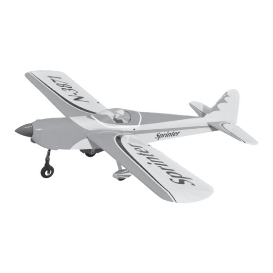
SPECIFICATION
Wingspan :
1,580mm.
Length
: 1,265 mm.
Weight
:
2.5kg.
Parts Listing required (not included)
Radio :
4 channels
Servo :
5 servos.
Glow Engine : 46 - 55 cu.in. 2 stroke.
Instruction Manual book
62.20 in.
49.80in.
5.50lbs.
Electric Motor: BL 2826/06 OUTRUNER
Battery: 4 Cells-Li-Poly-14.8v - 5,000 mAh.
Speed Control:
Propeller :
60A.
12 x 6.
Made in Vietnam.
Advertisement
Table of Contents

Related Manuals for Black Horse Model Sprinter


Summary of Contents for Black Horse Model Sprinter
- Page 1 Instruction Manual book SPECIFICATION Electric Motor: BL 2826/06 OUTRUNER Wingspan : 1,580mm. 62.20 in. Battery: 4 Cells-Li-Poly-14.8v - 5,000 mAh. Length : 1,265 mm.
- Page 2 INSTRUCTION MANUAL ITEM CODE: BH71-A This instruction manual is designed to help you build a great flying aeroplane. Please read this manual thoroughly before starting assembly of your SPRINTER. Use the parts listing below to identify all parts. WARNING. Please be aware that this aeroplane is not a toy and if assembled or used incorrectly it is capable of causing injury to people or property.
-
Page 3: Safety Precaution
SPRINTER - INSTRUCTION MANUAL ITEM CODE: BH71-A 1. Aluminium landing gear. SAFETY PRECAUTION. 2. Wheels. + This is not a toy 3. Nose gear + Be sure that no other flyers are using your radio frequency. 4. Wheel pant. + Do not smoke near fuel 5.Electric motor ply of wood . - Page 4 SPRINTER - INSTRUCTION MANUAL ITEM CODE: BH71-A Remove covering Cut the covering away from the slot. 3. Drill 1,5mm pilot holes through the block of wood for each of the four mounting screws provided with the servo. Install servo into ai- leron servo tray as same as picture below.
- Page 5 SPRINTER - INSTRUCTION MANUAL ITEM CODE: BH71-A 1. Using a ruler & pen to draw a straight line as below picture. 2 x 10 mm. 5. Instal servo tray with aileron servo into the wing as same as picture below.
-
Page 6: Installing The Aileron Linkages
SPRINTER - INSTRUCTION MANUAL ITEM CODE: BH71-A INSTALLING THE AILERON LINKAGES. 1. Working with the aileron linkage for now, thread one clevis onto one of the threaded wires. M2 clevis. Snap keeper. M2 lock nut. 150mm 2. Attach the clevis to the outer hole in the control horn. -
Page 7: Installing The Engine Mount
SPRINTER - INSTRUCTION MANUAL ITEM CODE: BH71-A Bottom side Repeat the procedure for the other wing half. INSTALLING THE ENGINE MOUNT. THERE ARE TWO OPTIONS: 1. ELECTRIC MOTOR Secure 2. ENGINE MOUNT. OPTION 1: ELECTRIC MOTOR. 3x 15mm 3 x 15mm... - Page 8 SPRINTER - INSTRUCTION MANUAL ITEM CODE: BH71-A FUEL TANK. INSTALLING THE STOPPER ASSEMBLY 1. The stopper has been pre-assembled at Battery the factory. 2. Using a modeling knife, cut one length of silicon fuel line (the length of silicon fuel line is...
- Page 9 SPRINTER - INSTRUCTION MANUAL ITEM CODE: BH71-A silicon tube not included. Do not secure the tank into place perma- Vent tube Fuel pick- up tube nently until after balancing the airplane. You may need to remove the tank to mount the battery in the fuel tank compartment.
-
Page 10: Installing The Engine
SPRINTER - INSTRUCTION MANUAL ITEM CODE: BH71-A Drill a hole 2mm diameter. Secure INSTALLING THE ENGINE. Locate the long piece of wire used for the throttle pushrod. One end of the wire has been pre-bend in to a “Z” bend at the factory. This NOSE GEAR INSTALLATION. - Page 11 SPRINTER - INSTRUCTION MANUAL ITEM CODE: BH71-A Right side Secure Left side COWLING. 1. Slide the fiberglass cowl over the en- gine and line up the back edge of the cowl with the marks you made on the fuselage. 2. While keeping the back edge of the cowl flush with the marks, align the front of the cowl with the crankshaft of the engine.
- Page 12 SPRINTER - INSTRUCTION MANUAL ITEM CODE: BH71-A Right side Bottom side 4. Install the muffler and muffler extension onto the engine and make the cutout in the 3 x 12mm cowl for muffler clearance. Connect the fuel and pressure lines to the carburetor, muffler and fuel filler valve.
-
Page 13: Installing The Spinner
SPRINTER - INSTRUCTION MANUAL ITEM CODE: BH71-A After installing the adjustable metal con- INSTALLING THE SPINNER. nector apply a small drop of thin C/A to the bottom nut. This will prevent the con- Install the spinner backplate, propeller and nector from loosening during flight. - Page 14 SPRINTER - INSTRUCTION MANUAL ITEM CODE: BH71-A MAIN GEAR INSTALATION. PARTS REQUIRED 1) Assemble and mounting the wheel pants as shown in the following pictures. Secure 5x35mm 5x35mm 2) Using the hardware provided, mount the main landing gear to the fuselage.
-
Page 15: Horizontal Stabilizer
SPRINTER - INSTRUCTION MANUAL ITEM CODE: BH71-A ELEVATOR INSTALLATION. SERVO INSTALLATION. Temporary pin to 1. Install the rubber grommets and brass keep hinge centered. collets into the elevator servo. Test fit the servo into the servo tray. 2. Mount the servo to the tray using the ... - Page 16 SPRINTER - INSTRUCTION MANUAL ITEM CODE: BH71-A Check to mark sure the wing and stabi- lizer are paralell. If they are not, lightly sand the opening in the fuselage for the stabilizer until the stabilizer is paralell to the wing.
-
Page 17: Elevator Control Horn Installa- Tion
SPRINTER - INSTRUCTION MANUAL ITEM CODE: BH71-A ELEVATOR CONTROL HORN INSTALLA- TION. Elevator control horn install as same as the way of aileron control horn. Please see pic- tures below. Control horn of elevator. Elevator control horn Bottom side 2x12mm ELEVATOR PUSHROD INSTALLATION. -
Page 18: Rudder Servo Installation
SPRINTER - INSTRUCTION MANUAL ITEM CODE: BH71-A Secure. Cut. E l e v a t o r pushrod Snap keeper. Bend 90 degree. RUDDER SERVO INSTALLATION. Rudder servo install as same as method of elevator servo. See picture below: Rudder servo. -
Page 19: Vertical Installation
SPRINTER - INSTRUCTION MANUAL ITEM CODE: BH71-A VERTICAL INSTALLATION. See picture below: 1) Using a modeling knife, remove the covering from the top of the fuselage and the covering from over the precut hinge slot cut into the lower rear portion of the fuselage This slot accepts the lower vertical. - Page 20 SPRINTER - INSTRUCTION MANUAL ITEM CODE: BH71-A 6) When you are sure that everything is a aligned correctly, mix up a generous amount of 30 minute epoxy. Apply a thin layer to the Mark point slot in the mounting platform and to the verti- cal stabilizer mounting area.
-
Page 21: Rudder Control Horn Installa- Tion
SPRINTER - INSTRUCTION MANUAL ITEM CODE: BH71-A RUDDER CONTROL HORN INSTALLA- TION. Rudder control horn install as same as the way of aileron control horn. Please see pic- tures below. 2 x12mm. Rudder pushrod Mark point and drill 1.5mm ... - Page 22 SPRINTER - INSTRUCTION MANUAL ITEM CODE: BH71-A E l e v a t o r Pushrod. R u d d e r pushrod Nose gear pushrod Bend and cut after C/A glue C u t . Bottom side E l e v a t o r...
-
Page 23: Installing The Switch
SPRINTER - INSTRUCTION MANUAL ITEM CODE: BH71-A INSTALLING THE SWITCH. 1. Cut out the switch hole using a modeling knife. Use a 2mm drill bit and drill out the two mounting holes through the fuselage side. - Page 24 SPRINTER - INSTRUCTION MANUAL ITEM CODE: BH71-A 2. Attach the aluminium tube into the WING ATTACHMENT. fuselage. See picture wing attach to fuselage. Installing the fuselage hatch as same as pic- ture below. Wing bolt 4x20mm. Right wing Wing bolt.
-
Page 25: Control Throws
SPRINTER - INSTRUCTION MANUAL ITEM CODE: BH71-A *If possible, first attempt to balance the model by changing the position of the receiver bat- tery and receiver. If you are unable to obtain good balance by doing so, then it will be nec-... -
Page 26: Pre-Flight Check
5. Check the receiver antenna . It should be fully extended and not coiled up inside the fuselage. 6. Properly balance the propeller. We wish you many safe and enjoy- able flights with your SPRINTER.
Need help?
Do you have a question about the Sprinter and is the answer not in the manual?
Questions and answers