Table of Contents
Advertisement
Quick Links
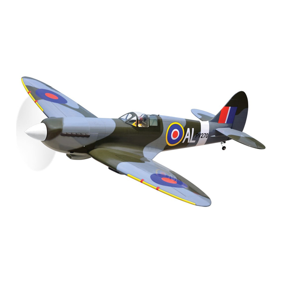
SPITFIRE MK
ALL BALSA - PLY WOOD CONSTRUCTION.
COVERED IN A HEAT-SHRINK FILM WITH PRINTED.
95% ALMOST READY TO FLY
SPECIFICATION
Wingspan: 1,730 mm (68.11 in).
Length: 1,520 mm (59.84 in).
Weight: 4.2 kg (9.24 lbs).
Wing area: 54.7 dm
Wing loading: 77 g/dm
Wing type: Naca Airfoil.
Spinner: 95mm.
Gear type: Air retract gear
with oleo struts (included).
Parts listing required (not included):
Radio: 06 channels.
Instruction Manual Book
2
.
2
.
Item code: BH149.
Servo: 08 servos.
Servo mount: 42mm x 21mm.
Engine: 91 - 4 stroke; O.S.GT15cc Gas.
Motor: Brushless outrunner 1200-2200W, 650KV.
Propeller: Suit with your engine.
Recommended Motor and Battery set up
(not included):
Motor: RIMFIRE.60.
Lipo cell: 6 cells 4,000-5,000mAh.
ESC: 80A.
Receiver battery: 6V/ 1200-2000mAh NiMH.
Made in Vietnam.
Advertisement
Table of Contents

Subscribe to Our Youtube Channel
Related Manuals for Black Horse Model BH149


Summary of Contents for Black Horse Model BH149
- Page 1 Instruction Manual Book Item code: BH149. SPITFIRE MK ALL BALSA - PLY WOOD CONSTRUCTION. COVERED IN A HEAT-SHRINK FILM WITH PRINTED. 95% ALMOST READY TO FLY SPECIFICATION Servo: 08 servos. Wingspan: 1,730 mm (68.11 in). Servo mount: 42mm x 21mm.
-
Page 2: Tools And Supplies Needed
SPITFIRE MK Item code: BH149. Instruction Manual This instruction manual is designed to help you build a great flying aeroplane. Please read this manual thoroughly SPITFIRE MK before starting assembly of your . Use the parts listing below to identify all parts. -
Page 3: Safety Precaution
SPITFIRE MK Item code: BH149. Instruction Manual Caution: This model is not a toy! This model is highly pre-fabricated and can be built in If you are a beginner to this type of powered model, a very short time. However, the work which you have to please ask an experienced model flyer for help and carry out is important and must be done carefully. -
Page 4: Installing The Ailerons
SPITFIRE MK Item code: BH149. Instruction Manual REPLACEMENT SMALL PARTS 3x15mm 3 x 12mm 5x35mm 3x6mm 3x4mm 4x30mm 4x70mm 1. Door mounting wheel. 2. Retract main gear. 3. Wheels. 3x12mm 4x30mm 4. Plastic parts for bottom wing. 5. Plastic - engine mount. -
Page 5: Installing The Aileron Servos
SPITFIRE MK Item code: BH149. Instruction Manual 2. INSTALLING THE AILERON SERVOS Electric wire 1) Install the rubber grommets and brass eyelets on to the aileron servos. 2) Using a modeling knife, remove the covering from over the pre-cut servo arm exit hole on the aileron servo tray / hatch. -
Page 6: Installing The Aileron Linkages
SPITFIRE MK Item code: BH149. Instruction Manual 3) Repeat the procedure to install the control horn on the opposite aileron. 4. INSTALLING THE AILERON LINKAGES Installing the aileron linkages as pictures below. lock nut Snap keeper. 100mm Using pliers, carefully make a 90 degree bend down at the mark made. - Page 7 SPITFIRE MK Item code: BH149. Instruction Manual 3x6mm 3 x 15mm Secure Secure Repeat the procedure to install the opposite gear. Install and secure the wheel. IV. PLASTIC PART OF BOTTOM WING See pictures below: Collar Secure 5x35mm 1. A/B Epoxy glue 2.Push in...
-
Page 8: Option 1: Electric Motor
SPITFIRE MK Item code: BH149. Instruction Manual OPTION 2: ENGINE MOUNT See pictures below: V. INSTALLING THE ENGINE MOUNT See pictures below: 4x30mm There are two options: 1. Electric motor 2. Engine mount. OPTION 1: ELECTRIC MOTOR Locate the long piece of wire used for the throttle pushrod. -
Page 9: Installing The Fuselage Servos
SPITFIRE MK Item code: BH149. Instruction Manual VI. SERVOS INSTALLATION Be sure to equip Not included. air vent pipe. Tygon tubing (Gas). And INSTALLING THE FUSELAGE SERVOS silicone tubing (Methanol). 1) Install the rubber grommets and brass collets To carburetor fuel inlet into the elevator, rudder and throttle servos. -
Page 10: Installing The Throttle Pushrod
SPITFIRE MK Item code: BH149. Instruction Manual 1) Slide the fiberglass cowl over the engine and 2. INSTALLING THE THROTTLE PUSHROD line up the back edge of the cowl with the marks you made on the fuselage. Install one adjustable metal connector through the third hole out from the center of one servo arm, enlarge the ... -
Page 11: Elevator Control Horn Installation
SPITFIRE MK Item code: BH149. Instruction Manual 2) Using a modeling knife, cut away the covering 5) With the horizontal stabilizer correctly aligned, mark the shape of the fuselage on the top and bottom from the fuselage for the stabilizer and remove it. -
Page 12: Elevator Pushrod Installation
SPITFIRE MK Item code: BH149. Instruction Manual 2. ELEVATOR PUSHROD INSTALLATION Bottom side. Drill a hole 1.5 mm Elevator pushrod Elevator control horn Silicone Tube M2 Lock nut When you are sure that everything is aligned 1) Using pliers, carefully make a 90 degree bend correctly, mix up a generous amount of 30 minute down at the mark made. -
Page 13: Mounting The Tail Wheel Bracket
SPITFIRE MK Item code: BH149. Instruction Manual Snap keeper Rudder pushrod Rudder servo Push in Flaslink Servo arm Pushrod wire XI. MOUNTING THE TAIL WHEEL BRACKET 1) Set the tail wheel assembly in place on the ply- wood plate. The pivot point of the tail wheel wire should be even with the rudder hinge line and the tail wheel bracket should be centered on the plywood plate. - Page 14 SPITFIRE MK Item code: BH149. Instruction Manual Valve control 3 way conector Connector Valve one way Drill a hole 2.5mm diameter Air line sets Air supply Air tank 3. Secure the tail wheel bracket in place using three 3mm x 12mm wood screws. Be careful not to overtighten the screws.
- Page 15 SPITFIRE MK Item code: BH149. Instruction Manual...
-
Page 16: Installing The Switch, Receiver And Battery
SPITFIRE MK Item code: BH149. Instruction Manual *** Test fit the aluminium tube dihedral brace into each XIII. INSTALLING THE SWITCH, wing haft. The brace should slide in easily. If not, use RECEIVER AND BATTERY 220 grit sand around the edges and ends of the brace until it fits properly. -
Page 17: Installing The Spinner
SPITFIRE MK Item code: BH149. Instruction Manual Open and Close Pillot XVI. INSTALLING THE SPINNER Install the spinner backplate, propeller and spinner A/B Epoxy glue. cone. The spinner cone is held in place using two 3mm x 8 mm machine screws. -
Page 18: Pre-Flight Check
SPITFIRE MK Item code: BH149. Instruction Manual Accurately mark the balance point on the top of the Control throw Ailerons: wing on both sides of the fuselage. The balance point Low: 12 mm up / down, 10% expo. is located 101mm back from the leading edge. This is High: 15 mm up / down, 10% expo. - Page 19 SPITFIRE MK Item code: BH149. Instruction Manual I/C FLINGT WARNINGS Always operate in open areas, away adjust the engine from ALWAYS from factories, hospitals, schools, NEVER fly near power lines, behind the propeller, and do not buildings and houses etc. NEVER...
Need help?
Do you have a question about the BH149 and is the answer not in the manual?
Questions and answers