Table of Contents
Advertisement
Quick Links
Instruction Manual book
ITEM CODE:BH113.
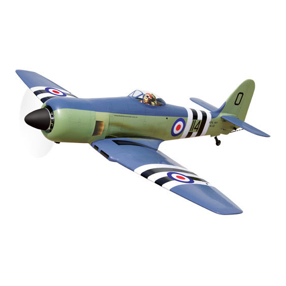
SPECIFICATION
Wingspan :
1,671 mm
65.79 in.
Length
:
1,620 mm
63.78 in.
Weight
:
4.8 kg
10.56 Lbs.
Radio
:
08 channels.
Servo :
8 Servos + 2 servos Retract (HITEC HS-75BB)
Engine :
20-22 CC Gas
Made in Vietnam.
Advertisement
Table of Contents

Subscribe to Our Youtube Channel
Related Manuals for Black Horse Model Sea Fury


Summary of Contents for Black Horse Model Sea Fury
- Page 1 Instruction Manual book ITEM CODE:BH113. SPECIFICATION Wingspan : 1,671 mm 65.79 in. Length 1,620 mm 63.78 in. Weight 4.8 kg 10.56 Lbs. Radio 08 channels.
- Page 2 Item code:BH113 INSTRUCTION MANUAL. This instruction manual is designed to help you build a great flying aeroplane. Please read this manual thoroughly before starting assembly of your SEA FURY. Use the parts listing below to identify all parts. WARNING. Please be aware that this aeroplane is not a toy and if assembled or used incorrectly it is capable of causing injury to people or property.
-
Page 3: Safety Precaution
SEA FURY - Item code:BH113 INSTRUCTION MANUAL. Caution: this model is not a toy! If you are a beginner to this type of powered model, please ask an experienced model flyer for help and support. If you attempt to operate the model without knowing what you are doing you could easily injure yourself or somebody else. -
Page 4: Installing The Aileron Servos
SEA FURY - Item code:BH113 INSTRUCTION MANUAL. REPLACEMENT SMALL PARTS I. AILERON. 1. Door mounting wheel. 1.INSTALLING THE AILERON SERVOS. 2.Retract main gear. 1) Install the rubber grommets and brass eyelets onto the aileron servos. 3. Spinner. 4. Fuel tank. - Page 5 SEA FURY - Item code:BH113 INSTRUCTION MANUAL. C/A glue. C/A glue. 3) Drill 1,6mm pilot holes through the block of wood for each of the four mounting screws C/A glue. provided with the servo. Thread 4. Instal servo tray with aileron servo into C/A glue.
-
Page 6: Installing The Aileron Linkages
SEA FURY - Item code:BH113 INSTRUCTION MANUAL. 3.INSTALLING THE AILERON LINKAGES. Installing the aileron linkages as pictures below. Secure. 2x8mm. 70 mm 2.INSTALLING THE AILERON CONTROL HORN. 2x8mm. Secure. 3mm x 20mm. Repeat the procedure for the other wing half. - Page 7 SEA FURY - Item code:BH113 INSTRUCTION MANUAL. Secure. C/A glue. C/A glue. Flap C/A glue. C/A glue. 3mm x 15mm. C/A glue.
- Page 8 SEA FURY - Item code:BH113 INSTRUCTION MANUAL. Control horn of the flap 2. INSTALLING THE FLAP SERVOS INSTALLING THE FLAP LINKAGES. Installing the aileron linkages as pictures below. 2x8mm. 70 mm 2x8mm. Secure. Electric wire Thread 2 x 8mm secure.
- Page 9 SEA FURY - Item code:BH113 INSTRUCTION MANUAL. Bottom side. Repeat the procedure for the other wing half. INSTALLING AIR RETRACTABLE LANDING GEAR. 3 x 16mm. 3 x16mm. 3 x 15mm. 3 x 15mm. Mark point.
- Page 10 SEA FURY - Item code:BH113 INSTRUCTION MANUAL. 3x15mm Secure. Secure.
- Page 11 SEA FURY - Item code:BH113 INSTRUCTION MANUAL. Secure Drill a hole 3.5mm diameter Drill a hole 3.5mm diameter M3 Lock nut 3 x 16 mm Secure Secure...
- Page 12 SEA FURY - Item code:BH113 INSTRUCTION MANUAL. M3 Lock nut. Lock. Lock. Connector. Connector.
-
Page 13: Installing The Engine Mount
SEA FURY - Item code:BH113 INSTRUCTION MANUAL. Bottom side Repeat the procedure for the other wing half. INSTALLING THE ENGINE MOUNT. See pictures below: Front view Secure. Drill a hole 6mm diameter... -
Page 14: Installing The Engine
SEA FURY - Item code:BH113 INSTRUCTION MANUAL. INSTALLING THE ENGINE. See pictures below: Secure. Secure. 60mm 5x80mm Tie wrap. Tie wrap. -
Page 15: Installing The Throttle - Pushrod
SEA FURY - Item code:BH113 INSTRUCTION MANUAL. INSTALLING THE THROTTLE - PUSHROD. 1. Install one adjustable metal connector through the third hole out from the center of one servo arm, enlarge the hole in the servo arm using a 2mm drill bit to accommodate the servo connector. - Page 16 SEA FURY - Item code:BH113 INSTRUCTION MANUAL. Blow through one of the lines to ensure the fuel lines have not become kinked inside the fuel tank compartment. Air should flow through easily. 9) To secure the fuel tank in place, apply a...
- Page 17 SEA FURY - Item code:BH113 INSTRUCTION MANUAL. Tie wrap. COWLING. 1. Slide the fiberglass cowl over the en- gine and line up the back edge of the cowl with the marks you made on the fuselage. Top side Fuel Tank Bottom side Cut.
-
Page 18: Installing The Spinner
SEA FURY - Item code:BH113 INSTRUCTION MANUAL. Trim and cut. Front view. 2. While keeping the back edge of the cowl flush with the marks, align the front of the cowl with the crankshaft of the engine. The front of the cowl should be positioned so the INSTALLING THE SPINNER. -
Page 19: Horizontal Stabilizer
SEA FURY - Item code:BH113 INSTRUCTION MANUAL. HORIZONTAL STABILIZER. See pictures below: ELEVATOR INSTALLATION. SERVO INSTALLATION. 1. Install the rubber grommets and brass collets into the elevator servo. Test fit the servo into the servo tray. 2. Mount the servo to the tray using the mounting screws provided with your radio sys- tem. - Page 20 SEA FURY - Item code:BH113 INSTRUCTION MANUAL. C/A glue. C/A glue. 9 mm 277 mm C/A glue.
- Page 21 SEA FURY - Item code:BH113 INSTRUCTION MANUAL. Bottom side. 2 x 8mm. ELEVATOR CONTROL HORN AND ELEVATOR PUSHROD INSTALLATION. Plastic parts of elevator 3 x20mm. pushrod. Cut. Elevator control horn. C/A glue...
-
Page 22: Rudder Control Horn Installation
SEA FURY - Item code:BH113 INSTRUCTION MANUAL. RUDDER CONTROL HORN Bottom side INSTALLATION. Rudder control horn install as same as the way of aileron control horn. Please see pic- tures below. Elevator Elevator pushrod pushrod Control horn of Rudder. 2 x 8mm. -
Page 23: Rudder Pushrod Installation
SEA FURY - Item code:BH113 INSTRUCTION MANUAL. Bottom side C/A glue. Rudder control horn. MOUNTING THE TAIL WHEEL BRACKET. C/A glue. 1. Set the tail wheel assembly in place on the plywood plate. The pivot point of the... - Page 24 SEA FURY - Item code:BH113 INSTRUCTION MANUAL. 70 mm 2x8mm. R e m o v e covering Tail gear pushrod. Epoxy glue. Plastic part for tail gear Epoxy glue. Mark line.
-
Page 25: Installing The Switch
SEA FURY - Item code:BH113 INSTRUCTION MANUAL. 2 x 8mm C/A glue Secure. C/A glue Rudder Elevator pushrod. pushrod Tail gear pushrod. Bottom side. INSTALLING THE SWITCH. 1) Cut out the switch hole using a modeling knife. -
Page 26: Installing The Receiver And Battery
SEA FURY - Item code:BH113 INSTRUCTION MANUAL. INSTALLING THE RECEIVER AND BATTERY. 1. Plug the servo leads and the switch lead into the receiver. You may want to plug an aileron extension into the receiver to make plugging in the aileron servo lead easier when you are installing the wing . - Page 27 SEA FURY - Item code:BH113 INSTRUCTION MANUAL. Right wing. Secure See picture wing attach to fuselage. Wing bolt. Left wing. Drill a hole 3mm diameter Drill a hole 3mm diameter Secure 4 x 40mm...
-
Page 28: Control Throws
SEA FURY - Item code:BH113 INSTRUCTION MANUAL. Top side. CONTROL THROWS. BALANCING. 1) We highly recommend setting up a 1) It is critical that your airplane be bal- plane using the control throws listed. -
Page 29: Pre-Flight Check
5) Check the receiver antenna . It should be fully extended and not coiled up inside the fuselage. 6) Properly balance the propeller. We wish you many safe and enjoyable flights with your SEA FURY...
Need help?
Do you have a question about the Sea Fury and is the answer not in the manual?
Questions and answers