Table of Contents
Advertisement
Quick Links
Download this manual
See also:
Instruction Manual
Advertisement
Table of Contents

Related Manuals for Black Horse Model SEA FURY


Summary of Contents for Black Horse Model SEA FURY
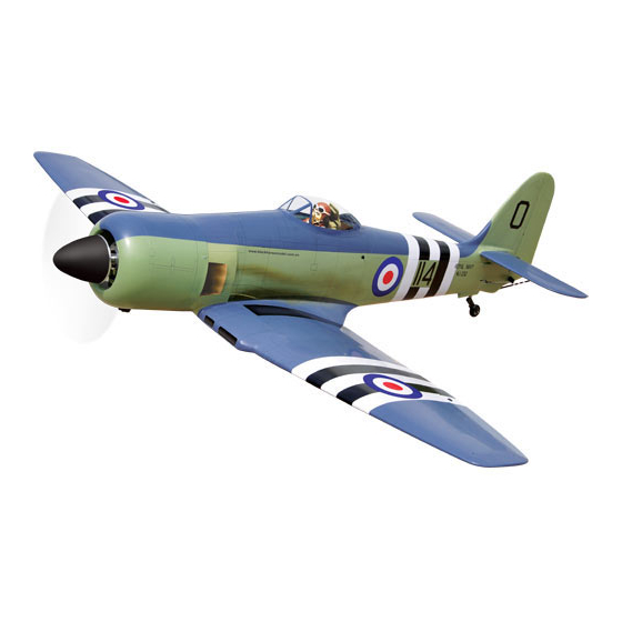
- Page 1 Instruction Manual book ITEM CODE:BH102. SPECIFICATION Wingspan : 1,950 mm 76.77 in. Length 1,757 mm 69.17 in. Weight 6.8 kg 14.96 Lbs. Radio 06 channels. Servo 08 servos. Engine 35 CC Made in Vietnam.
- Page 2 Item code:BH102 INSTRUCTION MANUAL. This instruction manual is designed to help you build a great flying aeroplane. Please read this manual thoroughly before starting assembly of your SEA FURY. Use the parts listing below to identify all parts. WARNING. Please be aware that this aeroplane is not a toy and if assembled or used incorrectly it is capable of causing injury to people or property.
-
Page 3: Safety Precaution
SEA FURY - Item code:BH102 INSTRUCTION MANUAL. Caution: this model is not a toy! If you are a beginner to this type of powered model, please ask an experienced model flyer for help and support. If you attempt to operate the model without knowing what you are doing you could easily injure yourself or somebody else. -
Page 4: Installing The Aileron Servos
SEA FURY - Item code:BH102 INSTRUCTION MANUAL. REPLACEMENT SMALL PARTS 3 x 15mm 3 x 15mm 3 x 10mm 3 x 10mm 3 x 15mm I. AILERON. 1.Door mounting wheel. 2.Air retract main gear. 1.INSTALLING THE AILERON SERVOS. 3.Wheels. 1) Install the rubber grommets and brass eyelets onto the aileron servos. -
Page 5: Installing The Aileron Linkages
SEA FURY - Item code:BH102 INSTRUCTION MANUAL. 2.INSTALLING THE AILERON CONTROL HORN. 3mm x 20mm. 3) Using the thread as a guide and using masking tape, tape the servo lead to the end of the thread: carefully pull the thread out. -
Page 6: Installing The Flap Servos
SEA FURY - Item code:BH102 INSTRUCTION MANUAL. Secure. C/A glue. Secure. C/A glue. C/A glue. Repeat the procedure for the other wing half. II. FLAP. 1.INSTALLING THE FLAP SERVOS. Flap Flap... - Page 7 SEA FURY - Item code:BH102 INSTRUCTION MANUAL. Electric wire C/A glue. Thread 2x10mm. C/A glue. Secure. INSTALLING THE FLAP LINKAGES. Installing the aileron linkages as pictures below. 2. INSTALLING THE FLAP CONTROL HORN. 2x8mm. 3mm x 15mm. 75 mm Secure.
- Page 8 SEA FURY - Item code:BH102 INSTRUCTION MANUAL. Repeat the procedure for the other wing half. INSTALLING AIR RETRACTABLE LANDING GEAR. 3 x 15mm. 3 x 15mm. 3x15mm 3 x 10mm. 3 x 10mm. Valve control. Secure.
- Page 9 SEA FURY - Item code:BH102 INSTRUCTION MANUAL.
- Page 10 SEA FURY - Item code:BH102 INSTRUCTION MANUAL. Secure Lock nut 3 x 10 mm Secure Secure...
- Page 11 SEA FURY - Item code:BH102 INSTRUCTION MANUAL. Lock. Drill a hole 3.5mm diameter Lock. Drill a hole 3.5mm diameter Drill a hole 3.5mm diameter Bottom side Drill a hole 3.5mm diameter...
-
Page 12: Installing The Engine Mount
SEA FURY - Item code:BH102 INSTRUCTION MANUAL. Bottom side Repeat the procedure for the other wing half. FUEL TANK. INSTALLING THE ENGINE MOUNT. See pictures below: INSTALLING THE STOPPER ASSEMBLY 4 x 30 mm 1) The stopper has been pre-assembled at the factory. - Page 13 SEA FURY - Item code:BH102 INSTRUCTION MANUAL. Do not secure the tank into place perma- nently until after balancing the airplane. You may need to remove the tank to mount the battery in the fuel tank compartment (Silicon tube not included) Silicon tube.
-
Page 14: Installing The Throttle - Cable
SEA FURY - Item code:BH102 INSTRUCTION MANUAL. INSTALLING THE THROTTLE - CABLE. 1. Install one adjustable metal connector through the third hole out from the center of one servo arm, enlarge the hole in the servo arm using a 2mm drill bit to accommodate the servo connector. - Page 15 SEA FURY - Item code:BH102 INSTRUCTION MANUAL. Bottom side 1. Slide the fiberglass cowl over the en- gine and line up the back edge of the cowl with the marks you made on the fuselage. 2. While keeping the back edge of the cowl flush with the marks, align the front of the cowl with the crankshaft of the engine.
- Page 16 SEA FURY - Item code:BH102 INSTRUCTION MANUAL. Mark point. 3 x 15mm Drill a hole 2mm diameter. Secure. Mark point . Secure. Mark line. Mark point.
-
Page 17: Installing The Spinner
SEA FURY - Item code:BH102 INSTRUCTION MANUAL. Machine screw. Drill a hole 2mm diameter. Right side 3 x 12mm Front view. Secure INSTALLING THE SPINNER. Install the spinner backplate, propeller and spinner cone. The spinner cone is held in place using two 3mm x 12mm wood screws. -
Page 18: Horizontal Stabilizer
SEA FURY - Item code:BH102 INSTRUCTION MANUAL. HORIZONTAL STABILIZER. See pictures below: 3 x12mm ELEVATOR INSTALLATION. 9 mm SERVO INSTALLATION. 277 mm 1. Install the rubber grommets and brass collets into the elevator servo. Test fit the servo into the servo tray. - Page 19 SEA FURY - Item code:BH102 INSTRUCTION MANUAL. 3 x15mm Elevator control horn. Bottom side 2 x 8mm. ELEVATOR CONTROL HORN AND ELEVATOR PUSHROD INSTALLATION. 3 x15 mm.
-
Page 20: Vertical Installation
SEA FURY - Item code:BH102 INSTRUCTION MANUAL. Plastic parts of elevator pushrod. Secure. Cut. VERTICAL INSTALLATION. Rudder servo install as same as method of elevator servo. See picture below: Rudder servo C/A glue RUDDER CONTROL HORN INSTALLATION. Rudder control horn install as same as the way of aileron control horn. -
Page 21: Rudder Pushrod Installation
SEA FURY - Item code:BH102 INSTRUCTION MANUAL. Aluminium Aluminium Cut. A+B PLUS glue A+B PLUS Glue. RUDDER PUSHROD INSTALLATION. 1. Rudder pushrod install as same as the way of aileron control horn. 2. Rudder push - pull system install as... -
Page 22: Mounting The Tail Wheel Bracket
SEA FURY - Item code:BH102 INSTRUCTION MANUAL. 1. Set the tail wheel assembly in place on the plywood plate. The pivot point of the tail wheel wire should be even with the rud- der hinge line and the tail wheel bracket should be centered on the plywood plate. - Page 23 SEA FURY - Item code:BH102 INSTRUCTION MANUAL. Cut. Secure Tail gear pushrod. Elevator Rudder pushrod pushrod. Tail gear pushrod. Mark point Plastic part for tail gear R e m o v e covering Cut. Cut.
- Page 24 SEA FURY - Item code:BH102 INSTRUCTION MANUAL. Epoxy glue. Epoxy glue. INSTALLATION SERVO AIR RETRACT- ABLE LANDING GEAR . Va l v e control Valve one way Air tank 3 way conector Air tank Air supply Valve one way C/A glue...
- Page 25 SEA FURY - Item code:BH102 INSTRUCTION MANUAL. Secure INSTALLING AIR TANK. Air tank INSTALLING SERVO USING FOR VALUE Air tank CONTROL .
-
Page 26: Installing The Switch
SEA FURY - Item code:BH102 INSTRUCTION MANUAL. switch ubec Air supply INSTALLING THE SWITCH. 1) Cut out the switch hole using a modeling knife. Use a 2mm drill bit and drill out the two mounting holes through the fuselage side. - Page 27 SEA FURY - Item code:BH102 INSTRUCTION MANUAL. Drill a hole 3mm diameter 4 x 40mm Secure Right wing. See picture wing attach to fuselage. Wing bolt. Left wing. Secure...
- Page 28 SEA FURY - Item code:BH102 INSTRUCTION MANUAL. BALANCING. 1) It is critical that your airplane be bal- anced correctly. Improper balance will cause your plane to lose control and crash. THE CENTER OF GRAVITY IS LOCATED Drill a hole 138MM BACK FROM THE LEADING EDGE 3mm diameter OF THE WING.
-
Page 29: Control Throws
4) Check the control surface. 5) Check the receiver antenna . It should be fully extended and not coiled up inside the fuselage. 6) Properly balance the propeller. We wish you many safe and enjoyable flights with your SEA FURY...
Need help?
Do you have a question about the SEA FURY and is the answer not in the manual?
Questions and answers