
Related Manuals for Black Horse Model Silence Twister


Summary of Contents for Black Horse Model Silence Twister
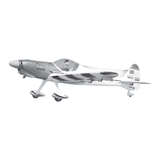
- Page 1 Instruction Manual book ITEM CODE :BH 110. SPECIFICATION Wingspan : 1,870 mm 73.62 in. Length 1,600mm 62.99in. Weight 4.6 kg 10.12 Lbs. Radio 05 channels. Servo 07 servos. Engine 15cc gas Made in Vietnam.
- Page 2 Instruction Manual Item code: BH 110 This instruction manual is designed to help you build a great flying aeroplane. Please read this manual thoroughly before starting assembly of your SILENCE TWISTER. Use the parts listing below to identify all parts. WARNING.
-
Page 3: Safety Precaution
Silence Twister - Instruction Manual Item code: BH 110 Caution: this model is not a toy! Caution! do not heat the film more than is If you are a beginner to this type of powered absolutely necessary. If the air or the iron is... -
Page 4: Installing The Aileron Servos
Silence Twister - Instruction Manual Item code: BH 110 A. Cowling. B. Wing panel. C. Fuselage. D . Horizon stabilizer. E. Aluminium wing dihedral brace. G. Decal sheet. REPLACEMENT SMALL PARTS I. AILERON. 1. Aluminium landing gear. 1.INSTALLING THE AILERON SERVOS. - Page 5 Silence Twister - Instruction Manual Item code: BH 110 Secure. Secure Bottom side Repeat the procedure for the other wing 3) Using the thread as a guide and using half. masking tape, tape the servo lead to the end 2.INSTALLING THE AILERON CONTROL HORN of the thread: carefully pull the thread out.
-
Page 6: Installing The Aileron Linkages
Silence Twister - Instruction Manual Item code: BH 110 3.INSTALLING THE AILERON II. FLAP. LINKAGES. 1.INSTALLING THE FLAP SERVOS. Installing the aileron linkages as pictures below. 70mm Thread Servo tray 2 x 8 mm E l e c t r i c wire Secure. -
Page 7: Installing The Engine Mount
Silence Twister - Instruction Manual Item code: BH 110 Aileron Flap Flap Bottom side Repeat the procedure for the other wing half. INSTALLING THE ENGINE MOUNT. See pictures below: Flap control horn. 3. INSTALLING THE FLAP LINKAGES. Installing the aileron linkages as pictures below. -
Page 8: Installing The Engine
Silence Twister - Instruction Manual Item code: BH 110 INSTALLING THE ENGINE- Secure. Top side. FUEL TANK. INSTALLING THE STOPPER ASSEMBLY 1) The stopper has been pre-assembled at the factory. Mount ply of 2) Using a modeling knife, cut one length wood . - Page 9 Silence Twister - Instruction Manual Item code: BH 110 (Silicon tube not included) Silicon tube. Secure Fuel pick- up tube Vent tube Fuel fill tube 5) Test fit the stopper assembly into the tank. It may be necessary to remove some of the flashing around the tank opening using a modeling knife.
- Page 10 Silence Twister - Instruction Manual Item code: BH 110 INSTALLING THE THROTTLE - CABLE. 1. Install one adjustable metal connector through the third hole out from the center of Throttle one servo arm, enlarge the hole in the servo cable.
- Page 11 Silence Twister - Instruction Manual Item code: BH 110 1. Slide the fiberglass cowl over the en- gine and line up the back edge of the cowl with the marks you made on the fuselage. Secure. 2. While keeping the back edge of the cowl flush with the marks, align the front of the cowl with the crankshaft of the engine.
- Page 12 Silence Twister - Instruction Manual Item code: BH 110 Drill a hole 3mm diameter Mark point. Mark point. Mark point. Drill a hole 3mm diameter Mark point. 3 x 12 mm.
-
Page 13: Installing The Spinner
Silence Twister - Instruction Manual Item code: BH 110 INSTALLING THE SPINNER. Bottom side Install the spinner backplate, propeller and Secure. spinner cone. The spinner cone is held in place using two 3mm x 12mm wood screws. Left side. Machine screw. -
Page 14: Horizontal Stabilizer
Silence Twister - Instruction Manual Item code: BH 110 ELEVATOR INSTALLATION. SERVO INSTALLATION. B o t t o m 1. Install the rubber grommets and brass side. collets into the elevator servo. Test fit the servo into the servo tray. -
Page 15: Elevator Control Horn Installation
Silence Twister - Instruction Manual Item code: BH 110 Epoxy glue. Elevator control horn. 2 x8mm C/A glue Secure. Plastic parts of elevator and rudder pushrod. Bottom side. ELEVATOR CONTROL HORN INSTALLATION. Elevator control horn install as same as the way of aileron control horn. -
Page 16: Rudder Control Horn Installa- Tion
Silence Twister - Instruction Manual Item code: BH 110 C/A glue E l e v a t o r E l e v a t o r pushrod pushrod RUDDER CONTROL HORN INSTALLA- TION. Rudder control horn install as same as the way of aileron control horn. -
Page 17: Rudder Pushrod Installation
Silence Twister - Instruction Manual Item code: BH 110 C/A glue 2 x8mm Secure. RUDDER PUSHROD INSTALLATION. 1. Rudder pushrod install as same as MOUNTING THE TAIL WHEEL the way of aileron control horn. BRACKET. 2. Rudder push - pull system install as same as picture below. - Page 18 Silence Twister - Instruction Manual Item code: BH 110 Remove covering. Secure. Secure 2 x8mm Secure. Plastic part of tail gear.
- Page 19 Silence Twister - Instruction Manual Item code: BH 110 Elevator Elevator pushrod pushrod Rudder pushrod Secure. Tail gear. MAIN GEAR INSTALATION. Secure. PARTS REQUIRED Plastic parts for landing gear. 1) Assemble and mounting the wheel pants as shown in the following pictures.
- Page 20 Silence Twister - Instruction Manual Item code: BH 110 L a n d i n g gear. R e m o v e covering. Epoxy glue. C/A glue. Mark line. B o t t o m side. R e m o v e...
-
Page 21: Installing The Switch
Silence Twister - Instruction Manual Item code: BH 110 INSTALLING THE SWITCH. 1. Cut out the switch hole using a modeling knife. Use a 2mm drill bit and drill out the two Secure. mounting holes through the fuselage side. 2. Secure the switch in place using the two machine screws provided with the radio system. -
Page 22: Wing Attachment
Silence Twister - Instruction Manual Item code: BH 110 Right wing. See picture wing attach to fuselage. Wing bolt. Installing the fuselage hatch as same as pic- ture below. Receiver. WING ATTACHMENT. Drill a hole Locate the aluminium wing dihedral brace. - Page 23 Silence Twister - Instruction Manual Item code: BH 110 Secure. 4 x 40mm Secure Top side. BALANCING. 1) It is critical that your airplane be bal- anced correctly. Improper balance will cause your plane to lose control and crash. THE CENTER OF GRAVITY IS LOCATED Left wing.
-
Page 24: Pre-Flight Check
Ailerons : 15mm up 15mm down We wish you many safe and enjoyable Elevator : 15mm up 15 mm down flights with your Silence Twister. Rudder : 25mm right 25mm left Flap : 35mm down...
Need help?
Do you have a question about the Silence Twister and is the answer not in the manual?
Questions and answers