Table of Contents
Advertisement
Quick Links
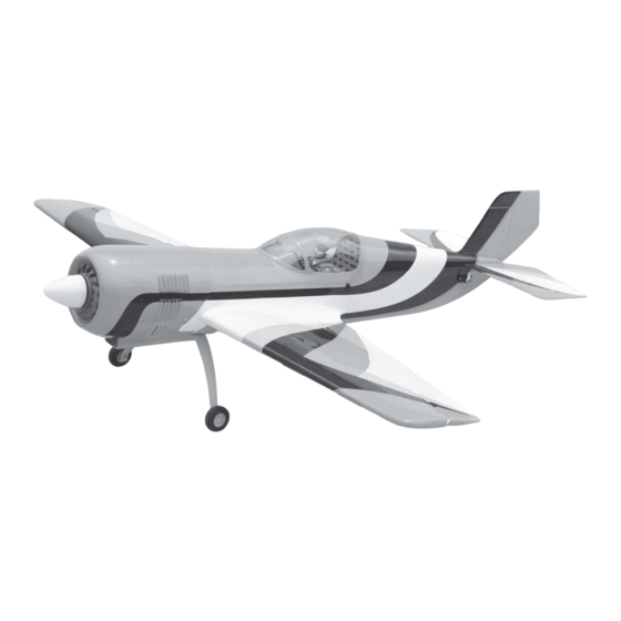
Instruction Manual book
SPECIFICATION
Wingspan :
Length
Weight
Radio
Servo
Electric Motor : EMAX BL 2815/09.
Battery
Speed control: 60 A.
Propeller:11 x 6
1,140 mm
:
1,063 mm
:
1.4 kg
:
04 channels.
: 05 mini servos(23.6 x 11.6 x 24mm)
0.92 x 0.45 x 0.94 in.
: 3 Cells-Li-Poly-11.1V 2.200 mAh.
44.88 in.
41.85 in.
3.08 Lbs.
Made in Vietnam.
Advertisement
Table of Contents

Subscribe to Our Youtube Channel
Related Manuals for Black Horse Model SU 26M-EP


Summary of Contents for Black Horse Model SU 26M-EP
- Page 1 Instruction Manual book SPECIFICATION Wingspan : 1,140 mm 44.88 in. Length 1,063 mm 41.85 in. Weight 1.4 kg 3.08 Lbs. Radio 04 channels. Servo : 05 mini servos(23.6 x 11.6 x 24mm) 0.92 x 0.45 x 0.94 in. Electric Motor : EMAX BL 2815/09. Battery : 3 Cells-Li-Poly-11.1V 2.200 mAh.
- Page 2 Instruction Manual Item code: BH97 This instruction manual is designed to help you build a great flying aeroplane. Please read this manual thoroughly before starting assembly of your SU 26M-EP. Use the parts listing below to identify all parts. WARNING.
-
Page 3: Safety Precaution
SU 26M-EP - Instruction Manual Item code: BH97 SAFETY PRECAUTION. + This is not a toy + Be sure that no other flyers are using your radio frequency. The glow plug clip must be securely attached to the glow plug. -
Page 4: Installing The Aileron Servos
SU 26M-EP - Instruction Manual Item code: BH97 C/A glue I. AILERON. 1.INSTALLING THE AILERON SERVOS. 1) Install the rubber grommets and brass eyelets onto the aileron servos. C/A glue 2) Using a modeling knife, remove the cov- ering at possition show below. -
Page 5: Installing The Aileron Linkages
SU 26M-EP - Instruction Manual Item code: BH97 5. Using the thread as a guide and using masking tape, tape the servo lead to the end of the thread: carefully pull the thread out. Secure. When you have pulled the servo lead out, re- move the masking tape and the servo lead from the thread. - Page 6 SU 26M-EP - Instruction Manual Item code: BH97 INSTALLING ELECTRIC MOTOR. 3 x 40 mm See pictures below: Right side. Drill a hole 5mm diameter Secure MAIN GEAR INSTALATION. PARTS REQUIRED 150 mm L a n d i n g gear.
- Page 7 SU 26M-EP - Instruction Manual Item code: BH97 2. While keeping the back edge of the cowl flush with the marks, align the front of the cowl with the crankshaft of the engine. The front of the cowl should be positioned so the crankshaft is in nearly the middle of the cowl opening.
-
Page 8: Installing The Spinner
SU 26M-EP - Instruction Manual Item code: BH97 INSTALLING THE SPINNER. SERVO ELEVATOR AND RUDDER Install the spinner backplate, propeller and 1. Install the rubber grommets and brass spinner cone. The spinner cone is held in collets into the elevator servo. Test fit the servo place using two 3mm x 12mm wood screws. - Page 9 SU 26M-EP - Instruction Manual Item code: BH97 3. Mark the shape of the vertical on the left and right sides onto the horizontal stabilizer using a felt-tip pen C/A glue Mark line 4. Remove the stabilizer. Using the lines...
- Page 10 SU 26M-EP - Instruction Manual Item code: BH97 6. After the epoxy has fully cured, remove Check to mark sure the wing and stabi- the masking tape or T-pins used to hold the lizer are paralell. If they are not, lightly sand...
- Page 11 SU 26M-EP - Instruction Manual Item code: BH97 C/A glue. C/A glue Top side. Bottom side. C/A glue. ELEVATOR CONTROL HORN AND ELEVATOR PUSHROD INSTALLATION. Elevator control horn install as same as the way of aileron control horn. Please see pic- tures below.
-
Page 12: Vertical Installation
SU 26M-EP - Instruction Manual Item code: BH97 E l e v a t o r E l e v a t o r pushrod pushrod C/A glue Bottom side C/A glue C/A glue VERTICAL INSTALLATION. Rudder servo install as same as method of elevator servo. - Page 13 SU 26M-EP - Instruction Manual Item code: BH97 Also carefully remove the covering from the horizontal fin as below the lines which you drew as same picture below. R e m o v e covering 1) Using a modeling knife, remove the...
- Page 14 SU 26M-EP - Instruction Manual Item code: BH97 RUDDER CONTROL HORN AND RUDDER PUSHROD INSTALLATION. Rudder control horn install as same as the way of aileron control horn. Please see pic- tures below. Epoxy glue. Rudder pushrod wire 6.) When you are sure that everything is a aligned correctly, mix up a generous amount of 30 minute epoxy.
- Page 15 SU 26M-EP - Instruction Manual Item code: BH97 Cut. Rudder pushrod. C/A glue E l e v a t o r Elevator pushrod pushrod INSTALLING THE RECEIVER AND BATTERY. Bottom side. 1. Plug the servo leads and the switch lead into the receiver. You may want to...
-
Page 16: Wing Attachment
SU 26M-EP - Instruction Manual Item code: BH97 3 x 15mm Battery. WING ATTACHMENT. Locate the aluminium wing dihedral brace. *** Test fit the aluminium tube dihedral brace into each wing haft. The brace should slide in easily. If not, use 220 grit sand around the edges and ends of the brace until it fits prop- erly. - Page 17 SU 26M-EP - Instruction Manual Item code: BH97 Installing the fuselage hatch as same as pic- ture below. Top side. BALANCING. 1) It is critical that your airplane be bal- anced correctly. Improper balance will cause your plane to lose control and crash.
-
Page 18: Control Throws
SU 26M-EP - Instruction Manual Item code: BH97 *If possible, first attempt to balance the model PRE-FLIGHT CHECK. by changing the position of the receiver bat- 1) Completely charge your transmitter and tery and receiver. If you are unable to obtain...
Need help?
Do you have a question about the SU 26M-EP and is the answer not in the manual?
Questions and answers