Black Horse Model Spitfire MK Instruction Manual Book
Hide thumbs
Also See for Spitfire MK:
- Instruction manual book (35 pages) ,
- Instruction manual book (20 pages)
Table of Contents
Advertisement
Quick Links
Advertisement
Table of Contents

Subscribe to Our Youtube Channel
Related Manuals for Black Horse Model Spitfire MK


Summary of Contents for Black Horse Model Spitfire MK
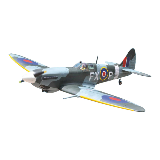
- Page 1 Instruction Manual book ITEM CODE:BH 136 SPECIFICATION Wingspan : 2,000mm 78.74 in. Length 1,760 mm 69.29 in. Weight 6.8kg 14.96 Lbs. Engine : 0.S GT 33cc gas ...
-
Page 2: Parts List
SPITFIRE MK Instruction Manual Item code: BH136 This instruction manual is designed to help you build a great flying aeroplane. Please read this SPITFIRE MK. manual thoroughly before starting assembly of your Use the parts listing below to identify all parts. -
Page 3: Safety Precaution
SPITFIRE MK Instruction Manual Item code: BH136 Caution: this model is not a toy! If you are a beginner to this type of powered model, please ask an experienced model flyer for help and support. If you attempt to operate the model without knowing what you are doing you could easily injure yourself or somebody else. - Page 4 SPITFIRE MK Instruction Manual Item code: BH136 REPLACEMENT LARGE PARTS A. Cowling. F1. Aluminium tube wing dihedral brace. B. Wing panel(B1,B2). C Fuselage. F2. Aluminium tube Horizontal stabilizer. D.Horizontal stabilizer(D1,D2). G. Decal sheet. E. Rudder. K.Pilot REPLACEMENT SMALL PARTS 3x15mm.
-
Page 5: Installing The Aileron Servos
SPITFIRE MK Instruction Manual Item code: BH136 2) Using a modeling knife, remove the cov- ering at possition show below. Servo tray. I. AILERON. 1.INSTALLING THE AILERON SERVOS. 1) Install the rubber grommets and brass eyelets onto the aileron servos. -
Page 6: Installing The Aileron Linkages
SPITFIRE MK Instruction Manual Item code: BH136 5. Instal servo tray with aileron servo into the wing as same as picture below. A+B Epoxy PLUS glue Electric wire. thread A+B Epoxy PLUS glue 2x10mm. Secure. Aileron control horn Repeat the procedure for the other wing half. - Page 7 SPITFIRE MK Instruction Manual Item code: BH136 Secure Bottom side Repeat the procedure for the other wing half. II. FLAP 1.INSTALLING THE FLAP SERVO Electric wire. 2x10mm. Flap. Bottom side Secure. Flap.
- Page 8 SPITFIRE MK Instruction Manual Item code: BH136 2.INSTALLING THE FLAP CONTROL HORN. Install flap control horn as same as picture below. Control horn Flap. Secure. A+B Epoxy PLUS glue Bottom side. Repeat the procedure for the other wing half. INSTALLING AIR RETRACTABLE LANDING GEAR.
- Page 9 SPITFIRE MK Instruction Manual Item code: BH136 Spring. Drill a hole 2mm diameter. hole 2mm. Spring.
- Page 10 SPITFIRE MK Instruction Manual Item code: BH136 Secure. Secure. 5x40mm...
- Page 11 SPITFIRE MK Instruction Manual Item code: BH136 S e c u r e 3x6mm. Drill a hole Bottom side 3x6mm. 3x4mm. Installing plastic parts for bottom wing. Secure 3x10mm. 3x4mm. Secure 3x4mm.
-
Page 12: Installing The Engine Mount
SPITFIRE MK Instruction Manual Item code: BH136 Bottom side. Repeat the procedure for the other wing half. INSTALLING THE ENGINE MOUNT. See pictures below: 3x 10mm Drill a hole 6mm diameter Secure. -
Page 13: Installing The Engine
SPITFIRE MK Instruction Manual Item code: BH136 INSTALLING THE ENGINE. Throttle servo. 5x70mm Throttle servo. Throttle pushrod. Secure. Right side. Front view. INSTALLING THE THROTTLE PUSHROD. 1. Install one adjustable metal connector through the third hole out from the center of... -
Page 14: Installing The Stopper Assembly
SPITFIRE MK Instruction Manual Item code: BH136 Secure. When the stopper assembly is installed in the tank, the top of the vent tube should rest just below the top surface of the tank. It should not touch the top of the tank. - Page 15 SPITFIRE MK Instruction Manual Item code: BH136 7) Using a modeling knife, cut 3 lengths of fuel line 150mm long. Connect 2 lines to the 2 vent tubes and 1 line to the fuel pickup tube in the stopper.
- Page 16 SPITFIRE MK Instruction Manual Item code: BH136 Left side COWLING. 1. Slide the fiberglass cowl over the en- gine and line up the back edge of the cowl with Pushrod Choke. the marks you made on the fuselage. Top side Pushrod Choke.
- Page 17 SPITFIRE MK Instruction Manual Item code: BH136 a hole 2.5mm diameter Trim and cut 3x 12mm Bottom side 3. Slide the cowl back over the engine and secure it in place using four wood screws. Secure. Left side Left side Drill a hole 2.5mm...
-
Page 18: Installing The Spinner
SPITFIRE MK Instruction Manual Item code: BH136 Front view. INSTALLING THE SPINNER. Install the spinner backplate, propeller and spinner cone. The spinner cone is held in 5x50mm. place using two 3mm x 8mm machine screws. Aluminium 10mm 5x50mm. Secure... -
Page 19: Installing The Elevator Servos
SPITFIRE MK Instruction Manual Item code: BH136 INSTALLING THE ELEVATOR Left side SERVOS. 1. Install the rubber grommets and brass collets into the elevator servo. Test fit the servo into the servo tray. 2. Mount the servo to the tray using the mounting screws provided with your radio system. -
Page 20: Elevator Control Horn Installation
SPITFIRE MK Instruction Manual Item code: BH136 Bottom side. ELEVATOR CONTROL HORN INSTALLATION. Elevator control horn install as same as the way of aileron control horn. Please see pic- Left horizontal tures below. stabilizer Bottom side A+B Epoxy PLus glue... -
Page 21: Elevator Pushrod Installation
SPITFIRE MK Instruction Manual Item code: BH136 M2 lock nut. Elevator control horn ELEVATOR PUSHROD INSTALLATION. Elevator pushrod install as same as the way of aileron pushrod. M2 lock nut. E l e v a t o r pushrod RUDDER INSTALLATION. - Page 22 SPITFIRE MK Instruction Manual Item code: BH136 R u d d e r Aluminium Aluminium Aluminium Push A+B Epoxy PLus glue...
-
Page 23: Rudder Control Horn Installa- Tion
SPITFIRE MK Instruction Manual Item code: BH136 RUDDER CONTROL HORN INSTALLA- RUDDER CABLE INSTALLATION. TION. 1. Rudder push - pull system install as Rudder control horn install as same as the same as picture below. way of aileron control horn. Please see pic- tures below. -
Page 24: Mounting The Tail Wheel Bracket
SPITFIRE MK Instruction Manual Item code: BH136 2. Secure the tail wheel bracket in place MOUNTING THE TAIL WHEEL using three 3mm x 15mm wood screws. Be BRACKET. careful not to overtighten the screws. 1. Set the tail wheel assembly in place on the plywood plate. - Page 25 SPITFIRE MK Instruction Manual Item code: BH136 Plastic parts of elevator pushrod and rudder cable. Top side. Cut. C/A glue. Push-pull cable tail gear. NSTALLING SERVO USING FOR VALVE CONTROL. C/A glue. valve control servo. Bottom side.
- Page 26 SPITFIRE MK Instruction Manual Item code: BH136 Valve control valve control servo. INSTALLATION AIR TANK Air tank Air tank Air tank Air supply Valve one way Secure. Right main gear wing Left main gear wing Valve control...
- Page 27 SPITFIRE MK Instruction Manual Item code: BH136...
-
Page 28: Installing The Switch
SPITFIRE MK Instruction Manual Item code: BH136 INSTALLING THE RECEIVER AND BATTERY. 1. Plug the servo leads and the switch lead into the receiver. You may want to plug an aileron extension into the receiver to make plugging in the aileron servo lead easier when you are installing the wing . -
Page 29: Wing Attachment
SPITFIRE MK Instruction Manual Item code: BH136 *** Test fit the aluminium tube dihedral brace into each wing haft. The brace should slide in easily. If not, use 220 grit sand around the edges and ends of the brace until it fits prop- erly. -
Page 30: Installing Cockpit Fuselage
SPITFIRE MK Instruction Manual Item code: BH136 Left wing. INSTALLING COCKPIT FUSELAGE . 3.Insert two wing panels as pictures below. See picture below: A +B Epoxy PLUS glue... - Page 31 SPITFIRE MK Instruction Manual Item code: BH136 C/A glue Front view. C/A glue C/A glue Left side. C/A glue See picture wing attach to fuselage. Installing the fuselage hatch as same as pic- ture below. Left wing. Installing plastic for Gun sets.
- Page 32 SPITFIRE MK Instruction Manual Item code: BH136 Installing Plastic parts for top wing Antenna A+B Epoxy PLUS glue Top Left side Secure. BALANCING. Top Left side 1) It is critical that your airplane be bal- anced correctly.
-
Page 33: Control Throws
5) Check the receiver antenna . It should be fully extended and not coiled up inside the fuselage. 6) Properly balance the propeller. We wish you many safe and enjoy- able flights with your Spitfire MK.
Need help?
Do you have a question about the Spitfire MK and is the answer not in the manual?
Questions and answers