Table of Contents
Advertisement
Quick Links
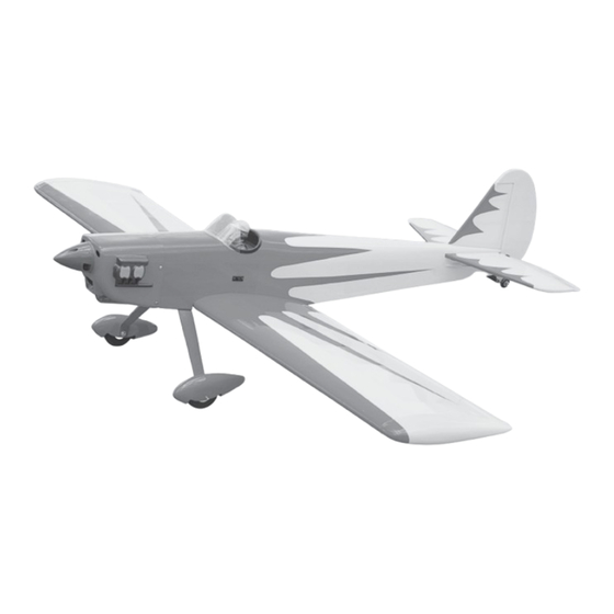
COVERED WITH ORACOVER.
SPECIFICATION
Wingspan :
1,550mm.
Length
: 1,180 mm.
Weight
:
2.5kg.
Parts Listing required (not included).
Radio :
4 channels.
Servo :
5 servos.
Glow Engine : 40-46 cu.in. 2 stroke.
Instruction Manual book
Electric Motor: BL 2826/06 OUTRUNER.
61.02 in.
Battery: 4 Cells-Li-Poly-14.8v- 5,000 mAh .
46.46in.
Speed Control:
5.50lbs.
Propeller :
60A.
12 x 6.
Made in Vietnam.
Advertisement
Table of Contents

Related Manuals for Black Horse Model SPACE WALKER


Summary of Contents for Black Horse Model SPACE WALKER
- Page 1 Instruction Manual book COVERED WITH ORACOVER. SPECIFICATION Electric Motor: BL 2826/06 OUTRUNER. Wingspan : 1,550mm. 61.02 in. Battery: 4 Cells-Li-Poly-14.8v- 5,000 mAh . Length : 1,180 mm.
- Page 2 Instruction Manual ITEM CODE: BH65-A. This instruction manual is designed to help you build a great flying aeroplane. Please read this manual thoroughly before starting assembly of your SPACE WALKER. Use the parts listing below to identify all parts. WARNING.
-
Page 3: Safety Precaution
SPACE WALKER - Instruction Manual ITEM CODE: BH65-A. 1. Aluminium landing gear. SAFETY PRECAUTION. 2. Wheel pants. + This is not a toy + Be sure that no other flyers are using your 3.Tail gear. radio frequency. 4.Wheels. + Do not smoke near fuel 5.Electric motor ply of wood (A,B). - Page 4 SPACE WALKER - Instruction Manual ITEM CODE: BH65-A. Assemble then apply drops of thin C/A to center of hinge,on both sides. Secure Servo tray 4. Using the thread as a guide and using masking tape, tape the servo lead to the end of the thread: carefully pull the thread out.
- Page 5 SPACE WALKER - Instruction Manual ITEM CODE: BH65-A. 2. Locate nylon control horn, nylon con- trol horn backplates . 3. Drill through 6mm (diameter) the aileron using the control horn as a guide and screw the control horn in place.
-
Page 6: Installing The Aileron Linkages
SPACE WALKER - Instruction Manual ITEM CODE: BH65-A. INSTALLING THE AILERON LINKAGES. 1. Working with the aileron linkage for now, thread one clevis onto one of the threaded wires. M2 lock nut. Snap keeper. M2 clevis. 2. Attach the clevis to the outer hole in the control horn. - Page 7 SPACE WALKER - Instruction Manual ITEM CODE: BH65-A. C/A glue Epoxy glue Battery OPTION 2: ENGINE MOUNT. Secure 4 x 25mm...
-
Page 8: Installing The Stopper Assembly
SPACE WALKER - Instruction Manual ITEM CODE: BH65-A. When the stopper assembly is installed in the tank, the top of the vent tube should rest just below the top surface of the tank. It should not touch the top of the tank. -
Page 9: Installing The Engine
SPACE WALKER - Instruction Manual ITEM CODE: BH65-A. 7. Using a modeling knife, cut 3 lengths of fuel line 150mm long. Connect 2 lines to the 2 vent tubes and 1 line to the fuel pickup tube in the stopper. - Page 10 SPACE WALKER - Instruction Manual ITEM CODE: BH65-A. Drill a hole 2.5mm diameter Right side Left side Pushrod wire Pushrod wire 3x 20mm Bottom side Left side Secure...
-
Page 11: Installing The Throttle Pushrod
SPACE WALKER - Instruction Manual ITEM CODE: BH65-A. Right side Secure. INSTALLING THE THROTTLE PUSHROD. Install one adjustable metal connector through the third hole out from the center of one servo arm, enlarge the hole in the servo arm using a 2mm drill bit to accommodate the servo connector. - Page 12 SPACE WALKER - Instruction Manual ITEM CODE: BH65-A. Right side Right side 2. While keeping the back edge of the cowl flush with the marks, align the front of Bottom side the cowl with the crankshaft of the engine. The...
-
Page 13: Installing The Spinner
SPACE WALKER - Instruction Manual ITEM CODE: BH65-A. MAIN GEAR INSTALATION. PARTS REQUIRED Font view 3 x 12mm INSTALLING THE SPINNER. Install the spinner backplate, propeller and spinner cone. The spinner cone is held in place using two 3mm x 12mm wood screws. - Page 14 SPACE WALKER - Instruction Manual ITEM CODE: BH65-A. INSTALLING THE MAIN LANDING GEAR. Bottom side 1. The blind nuts are already mounted inside the fuselage. 2. The holes in the landing gear should be to accept the mounting bolts.
- Page 15 SPACE WALKER - Instruction Manual ITEM CODE: BH65-A. See pictures below: HORIZONTAL STABILIZER INSTALLATION. 1. Draw a center line onto the horizontal See pictures below: stabilizer. Then slide the horizontal into the Top side fuselage. Center line Bottom side ...
- Page 16 SPACE WALKER - Instruction Manual ITEM CODE: BH65-A. Bottom side. Mark line. 4. Remove the stabilizer. Using the lines you just drew as a guide, carefully remove the covering from between them using a modeling knife. When cutting through the cover- ing to remove it, cut with only enough pres- sure to only cut through the covering it’s...
-
Page 17: Elevator Control Horn Installa- Tion
SPACE WALKER - Instruction Manual ITEM CODE: BH65-A. ELEVATOR CONTROL HORN INSTALLA- TION. Elevator control horn install as same as the way of aileron control horn. Please see pic- tures below. Control horn of elevator. 2x12mm C/A glue Top side ... -
Page 18: Elevator Pushrod Installation
SPACE WALKER - Instruction Manual ITEM CODE: BH65-A. 2) Install control horn as same as picture below. Cut. Control horn of elevator. ELEVATOR PUSHROD INSTALLATION. Elevator pushrod install as same as the way of aileron pushrod. M2 lock nut. -
Page 19: Vertical Installation
SPACE WALKER - Instruction Manual ITEM CODE: BH65-A. VERTICAL INSTALLATION. See picture below: Cut the covering Elevator away from the slot. pushrod Temporary pin to keep hinge centered. RUDDER SERVO INSTALLATION. Rudder servo install as same as method of elevator servo. See picture below:... - Page 20 SPACE WALKER - Instruction Manual ITEM CODE: BH65-A. 1) Using a modeling knife, remove the cov- 4. Now, remove the rudder and using a ering from the top of the fuselage and the cov- modeling knife, carefully cut just inside the...
-
Page 21: Rudder Control Horn Installa- Tion
SPACE WALKER - Instruction Manual ITEM CODE: BH65-A. Epoxy glue Drill a hole of the mounting rudder control horn on to the rudder with 1.5mm diameter. C/A glue Mark point and drill 1.5mm Top side. Secure. Bottom side. Rudder RUDDER CONTROL HORN INSTALLA- control. -
Page 22: Mounting The Tail Wheel Bracket
SPACE WALKER - Instruction Manual ITEM CODE: BH65-A. Rudder pushrod Rudder pushrod Elevator Elevator pushrod pushrod Rudder pushrod Elevator pushrod Bottom side. Bend and MOUNTING THE TAIL WHEEL cut after BRACKET. 1. Set the tail wheel assembly in place on the plywood plate. - Page 23 SPACE WALKER - Instruction Manual ITEM CODE: BH65-A. Secure 2.Mark the locations of the two mounting screw.Remove the tail wheel bracket and drill 2mm pilot holes at the locations marked. 3. Secure the tail wheel bracket in place using three 3mm x 12mm wood screws.
-
Page 24: Installing The Receiver And Battery
SPACE WALKER - Instruction Manual ITEM CODE: BH65-A. INSTALLING THE RECEIVER AND BATTERY. Bottom side. 1. Plug the servo leads and the switch lead into the receiver. You may want to plug an aileron extension into the receiver to make plugging in the aileron servo lead easier when you are installing the wing . -
Page 25: Wing Attachment
SPACE WALKER - Instruction Manual ITEM CODE: BH65-A. WING ATTACHMENT. 1.Locate the aluminium wing dihedral brace. Aluminium tube 19mm 430mm. *** Test fit the aluminium tube dihedral brace into each wing haft. The brace should slide in easily. If not, use 220 grit sand around the edges and ends of the brace until it fits prop- erly. - Page 26 SPACE WALKER - Instruction Manual ITEM CODE: BH65-A. Accurately mark the balance point on the top of the wing on both sides of the fuselage. The balance point is located 70mm back from the leading edge. This is the balance point at which your model should balance for your first flights.
-
Page 27: Control Throws
SPACE WALKER - Instruction Manual ITEM CODE: BH65-A. CONTROL THROWS. PRE-FLIGHT CHECK. 1. We highly recommend setting up a plane 1. Completely charge your transmitter and using the control throws listed.
Need help?
Do you have a question about the SPACE WALKER and is the answer not in the manual?
Questions and answers