Table of Contents
Advertisement
Quick Links
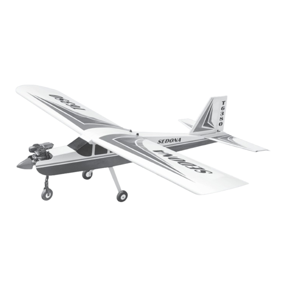
SPECIFICATION
Wingspan :
1,800mm.
Length
: 1,470 mm.
Weight
:
2.6kg.
Parts Listing required (not included).
Radio :
4 channels.
Servo :
4-5 servos.
Glow Engine : 46-55 cu.in. 2 stroke.
Instruction Manual book
Electric Motor: AXI 2826/10.
70.87 in.
Battery: 4-5 Cells-Li-Poly-14.8-18.5v- 5.000 mAh - 20 c .
57.871in.
Speed Control:
5.72lbs.
Propeller :
Recommended R.C: 4 channels with
ITEM CODE: BH68.
60A.
13 x 6.
4-5 servos.
Made in Vietnam.
Advertisement
Table of Contents

Related Manuals for Black Horse Model Sedona


Summary of Contents for Black Horse Model Sedona
- Page 1 Instruction Manual book ITEM CODE: BH68. SPECIFICATION Electric Motor: AXI 2826/10. Wingspan : 1,800mm. 70.87 in. Battery: 4-5 Cells-Li-Poly-14.8-18.5v- 5.000 mAh - 20 c . ...
-
Page 2: Parts List
Instruction Manual ITEM CODE: BH68. This instruction manual is designed to help you build a great flying aeroplane. Please read this manual thoroughly before starting assembly of your SEDONA. Use the parts listing below to identify all parts. WARNING. Please be aware that this aeroplane is not a toy and if assembled or used incorrectly it is capable of causing injury to people or property. -
Page 3: Safety Precaution
SEDONA - Instruction Manual ITEM CODE: BH68. INSTALLING THE AILERON SERVOS. SAFETY PRECAUTION. 1) Install the rubber grommets and brass + This is not a toy eyelets onto the aileron servo. + Be sure that no other flyers are using your radio frequency. - Page 4 SEDONA - Instruction Manual ITEM CODE: BH68. C/A glue Bottom side. 2) Place the mount onto the wing haft, aligning the cut out in the mount with the cut- out in the wing. The two notches in the mount should face the leading edge of the wing.
-
Page 5: Wing Assembly
SEDONA - Instruction Manual ITEM CODE: BH68. C/A glue Center line Bottom side. Mark point 7) Install the aileron servo into the servo mount, with the out put shaft towards the lead- ing edge of the wing, using the wood screws provided with your radio system. - Page 6 SEDONA - Instruction Manual ITEM CODE: BH68. Bottom side. Aluminium. Epoxy glue. Mark line. 3)Apply masking tape at the wing join to hold the wing halves together securely. Remove covering. Masking tape. Masking tape. Epoxy glue.
-
Page 7: Installing The Aileron Linkage
SEDONA - Instruction Manual ITEM CODE: BH68. INSTALLING THE AILERON LINKAGE. Snap keeper Nilon control claps 1) Thread one nylon adjustable control horn onto each aileron torque rod. Thread the horns on until they are flush with the ends of the torque rods. -
Page 8: Installing The Engine Mount
SEDONA - Instruction Manual ITEM CODE: BH68. INSTALLING THE ENGINE MOUNT. THERE ARE TWO OPTIONS: 3 x 15mm 1. ELECTRIC MOTOR 2. ENGINE MOUNT. OPTION 1: ELECTRIC MOTOR. Secure 3 x 15mm 3x 15mm Tie wrap C/A glue Epoxy glue... -
Page 9: Engine Mount
SEDONA - Instruction Manual ITEM CODE: BH68. 2. ENGINE MOUNT. When the stopper assembly is installed in the tank, the top of the vent tube should rest just below the top surface of the tank. It should not touch the top of the tank. -
Page 10: Installing The Engine
SEDONA - Instruction Manual ITEM CODE: BH68. Secure 8) Feed three lines through the fuel tank compartment and through the pre-drilled hole in the firewall. Pull the lines out from behind the engine, while guiding the fuel tank into place. -
Page 11: Nose Gear Installation
SEDONA - Instruction Manual ITEM CODE: BH68. NOSE GEAR INSTALLATION. Steering arm. 4 x 30mm Mark point Installing steering arm as follow Adjust the nose gear steering arm until the arm is parallel with the fire wall. Drill 4mm diameter. -
Page 12: Installing The Main Landing Gear
SEDONA - Instruction Manual ITEM CODE: BH68. INSTALLING THE MAIN LANDING GEAR. 1. The blind nuts are already mounted Secure inside the fuselage. 2. The holes in the landing gear should be to accept the mounting bolts. 3. Using the hardware provided, mount the main landing gear to the fuselage. -
Page 13: Installing The Throttle Pushrod
SEDONA - Instruction Manual ITEM CODE: BH68. INSTALLING THE THROTTLE PUSHROD. See pictures below: Throttle pushrod Install one adjustable metal connector through the third hole out from the center of one servo arm, enlarge the hole in the servo arm using a 2mm drill bit to accommodate the servo connector. - Page 14 SEDONA - Instruction Manual ITEM CODE: BH68. C/A glue. C/A glue. Bottom side. Top side. C/A glue. C/A glue. C/A glue. C/A glue. C/A glue. Check to mark sure the wing and stabi- lizer are paralell. If they are not, lightly sand the opening in the fuselage for the stabilizer until the stabilizer is paralell to the wing.
- Page 15 SEDONA - Instruction Manual ITEM CODE: BH68. When cutting through the covering to re- Center line move it, cut with only enough pressure to only cut through the covering itself. Cut- ting into the balsa structure may weaken ...
- Page 16 SEDONA - Instruction Manual ITEM CODE: BH68. ELEVATOR CONTROL HORN AND - ELEVATOR PUSHROD INSTALLATION. Elevator control horn install as same as the way of aileron control horn. Please see pic- tures below. Nilon control clasp 3 x 35mm M3 lock nut.
-
Page 17: Vertical Installation
SEDONA - Instruction Manual ITEM CODE: BH68. VERTICAL INSTALLATION. Rudder servo install as same as method of elevator servo. See picture below: Top elevator C/A glue. Elevator servo C/A glue. Elevator pushrod... - Page 18 SEDONA - Instruction Manual ITEM CODE: BH68. C/A glue. Remove covering C/A glue. Mark line C/A glue. When cutting through the covering to re- move it, cut with only enough pressure to only cut through the covering itself. Cutting into the balsa structure may weaken it.
-
Page 19: Rudder Control Horn Installa- Tion
SEDONA - Instruction Manual ITEM CODE: BH68. C/A glue RUDDER CONTROL HORN INSTALLA- Slide the vertical stabilizer back in place. Us- TION. ing a triangle, check to ensure that the vertical Rudder control horn install as same as the stabilizer is aligned 90 to the horizontal stabi- way of aileron control horn. - Page 20 SEDONA - Instruction Manual ITEM CODE: BH68. Drill a hole of the mounting rudder control horn on to the rudder with 6mm diameter. Rudder pushrod Secure M2 lock nut.
-
Page 21: Installing The Receiver And Battery
SEDONA - Instruction Manual ITEM CODE: BH68. INSTALLING THE RECEIVER AND BATTERY. Throttle pushrod 1. Plug the servo leads and the switch Elevator servo lead into the receiver. You may want to plug Elevator pushrod... -
Page 22: Wing Attachment
SEDONA - Instruction Manual ITEM CODE: BH68. Insert and secure WING ATTACHMENT. See picture wing attach to fuselage. Installing the fuselage hatch as same as pic- ture below. Wing bolt plate BALANCING. 1) It is critical that your airplane be bal- Wing bolt. -
Page 23: Pre-Flight Check
6. Properly balance the propeller. Ailerons : 15mm up 15mm down We wish you many safe and enjoy- Elevator : 10mm up 10mm down able flights with your SEDONA. Rudder : 15mm right 15mm left...
Need help?
Do you have a question about the Sedona and is the answer not in the manual?
Questions and answers