EWM Taurus 355 Basic TDM Operating Instructions Manual
Hide thumbs
Also See for Taurus 355 Basic TDM:
- Operating instruction (59 pages) ,
- Operating instructions manual (64 pages) ,
- Operating instructions manual (72 pages)
Table of Contents

Related Manuals for EWM Taurus 355 Basic TDM


Summary of Contents for EWM Taurus 355 Basic TDM
- Page 1 Operating instructions Welding machine Taurus 355 Basic TDM Taurus 405 Basic TDM Taurus 505 Basic TDM 099-005221-EW501 Observe additional system documents! 16.04.2014 Register now! For your benefit Jetzt Registrieren und Profitieren! www.ewm-group.com...
-
Page 2: General Instructions
+49 2680 181-0. A list of authorised sales partners can be found at www.ewm-group.com. Liability relating to the operation of this equipment is restricted solely to the function of the equipment. No other form of liability, regardless of type, shall be accepted. -
Page 3: Table Of Contents
Contents Notes on the use of these operating instructions Contents 1 Contents ..............................3 2 Safety instructions ..........................6 Notes on the use of these operating instructions ................6 Explanation of icons ........................7 General ............................8 Transport and installation ......................12 2.4.1 Ambient conditions ....................... - Page 4 Options ............................59 Welding torch cooling system ...................... 59 Transport systems ........................59 General accessories ........................59 10 Appendix A ............................60 10.1 Setting instructions ........................60 11 Appendix B ............................61 11.1 Overview of EWM branches......................61 099-005221-EW501 16.04.2014...
- Page 5 Contents Notes on the use of these operating instructions 099-005221-EW501 16.04.2014...
-
Page 6: Safety Instructions
Safety instructions Notes on the use of these operating instructions Safety instructions Notes on the use of these operating instructions DANGER Working or operating procedures which must be closely observed to prevent imminent serious and even fatal injuries. • Safety notes include the "DANGER" keyword in the heading with a general warning symbol. •... -
Page 7: Explanation Of Icons
Safety instructions Explanation of icons Explanation of icons Symbol Description Press Do not press Turn Switch Switch off machine Switch on machine ENTER ENTER (enter the menu) ENTER NAVIGATION NAVIGATION (Navigating in the menu) EXIT EXIT (Exit the menu) Time display (example: wait 4s/press) Interruption in the menu display (other setting options possible) Tool not required/do not use Tool required/use... -
Page 8: General
Safety instructions General General DANGER Electromagnetic fields! The power source may cause electrical or electromagnetic fields to be produced which could affect the correct functioning of electronic equipment such as IT or CNC devices, telecommunication lines, power cables, signal lines and pacemakers. •... - Page 9 Safety instructions General WARNING Smoke and gases! Smoke and gases can lead to breathing difficulties and poisoning. In addition, solvent vapour (chlorinated hydrocarbon) may be converted into poisonous phosgene due to the ultraviolet radiation of the arc! • Ensure that there is sufficient fresh air! •...
- Page 10 Safety instructions General CAUTION Obligations of the operator! The respective national directives and laws must be observed for operation of the machine! • National implementation of the framework directive (89/391/EWG), as well as the associated individual directives. • In particular, directive (89/655/EWG), on the minimum regulations for safety and health protection when staff members use equipment during work.
- Page 11 Safety instructions General CAUTION EMC Machine Classification In accordance with IEC 60974-10, welding machines are grouped in two electromagnetic compatibility classes (see technical data): Class A machines are not intended for use in residential areas where the power supply comes from the low-voltage public mains network.
-
Page 12: Transport And Installation
Safety instructions Transport and installation Transport and installation WARNING Incorrect handling of shielding gas cylinders! Incorrect handling of shielding gas cylinders can result in serious and even fatal injury. • Observe the instructions from the gas manufacturer and in any relevant regulations concerning the use of compressed air! •... -
Page 13: Ambient Conditions
Safety instructions Transport and installation 2.4.1 Ambient conditions CAUTION Installation site! The machine must not be operated in the open air and must only be set up and operated on a suitable, stable and level base! • The operator must ensure that the ground is non-slip and level, and provide sufficient lighting for the place of work. -
Page 14: Intended Use
Intended use Applications Intended use WARNING Hazards due to improper usage! Hazards may arise for persons, animals and material objects if the equipment is not used correctly. No liability is accepted for any damages arising from improper usage! • The equipment must only be used in line with proper usage and by trained or expert staff! •... -
Page 15: Documents Which Also Apply
Intended use Documents which also apply Documents which also apply 3.3.1 Warranty NOTE For further information, please see the accompanying supplementary sheets "Machine and Company Data, Maintenance and Testing, Warranty"! 3.3.2 Declaration of Conformity The designated machine conforms to EC Directives and standards in terms of its design and construction: •... -
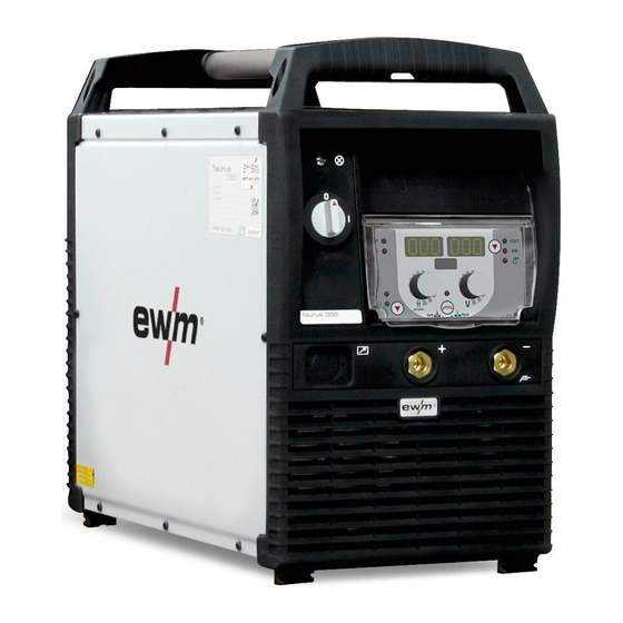
Page 16: Machine Description - Quick Overview
Machine description – quick overview Front view Machine description – quick overview NOTE The maximum possible machine configuration is given in the text description. If necessary, the optional connection may need to be retrofitted (see "Accessories" chapter). Front view Figure 4-1 099-005221-EW501 16.04.2014... - Page 17 Machine description – quick overview Front view Item Symbol Description Carrying handle Ready for operation signal light Signal light on when the machine is switched on and ready for operation Main switch, machine on/off Cooling air inlet Machine feet Connection socket, “+” welding current •...
-
Page 18: Rear View
Machine description – quick overview Rear view Rear view Figure 4-2 099-005221-EW501 16.04.2014... - Page 19 Machine description – quick overview Rear view Item Symbol Description Key button, Automatic cutout Wire feed motor supply voltage fuse (press to reset a triggered fuse) 19-pole connection socket (analogue) Wire feed unit control lead connection Connection socket, “+” welding current •...
-
Page 20: Machine Control - Operating Elements
Machine description – quick overview Machine control – Operating elements Machine control – Operating elements Figure 4-3 Item Symbol Description Button, welding process MIG/MAG welding MMA welding Air arc gouging Display, left Welding current, wire feed speed Status displays "Welding current display" signal light "Wire feed speed display"... - Page 21 Machine description – quick overview Machine control – Operating elements Item Symbol Description Push-button, throttling effect (arc dynamics) Arc is harder and more narrow Arc is softer and wider Rotary dial, arc length No function. Setting is made on the wire feed unit. Button, Parameter selection (right) VOLT Welding voltage...
-
Page 22: Design And Function
Design and function Machine control – Operating elements Design and function WARNING Risk of injury from electric shock! Contact with live parts, e.g. welding current sockets, is potentially fatal! • Follow safety instructions on the opening pages of the operating instructions. •... -
Page 23: Installation
Design and function Installation CAUTION Using protective dust caps! Protective dust caps protect the connection sockets and therefore the machine against dirt and damage. • The protective dust cap must be fitted if there is no accessory component being operated on that connection. -
Page 24: Protective Flap, Welding Machine Control
Design and function Machine cooling 5.1.1 Protective flap, welding machine control Figure 5-1 Item Symbol Description Protective cap Bracket, protective cap • Push the right-hand bracket of the protective cap to the right and remove the protective cap. Machine cooling To obtain an optimal duty cycle from the power components, the following precautions should be observed: •... -
Page 25: Notes On The Installation Of Welding Current Leads
Design and function Notes on the installation of welding current leads Notes on the installation of welding current leads NOTE Incorrectly installed welding current leads can cause faults in the arc (flickering). Lay the workpiece lead and hose package of power sources without HF igniter (MIG/MAG) for as long and as close as possible in parallel. - Page 26 Design and function Notes on the installation of welding current leads NOTE Use an individual welding lead to the workpiece for each welding machine! Figure 5-3 NOTE Fully unroll welding current leads, torch hose packages and intermediate hose packages. Avoid loops! Always keep leads as short as possible! Lay any excess cable lengths in meanders.
-
Page 27: Welding Torch Cooling System
Design and function Welding torch cooling system Welding torch cooling system 5.5.1 Welding torch cooling unit connection NOTE Observe the fitting and connection instructions given in the relevant operating instructions for the cooling unit. Figure 5-5 Item Symbol Description 4-pole connection socket Cooling unit voltage supply 8-pole connection socket Cooling unit control lead... -
Page 28: Mains Connection
Design and function Mains connection Mains connection DANGER Hazard caused by improper mains connection! An improper mains connection can cause injuries or damage property! • Only use machine with a plug socket that has a correctly fitted protective conductor. • If a mains plug must be fitted, this may only be carried out by an electrician in accordance with the relevant national provisions or regulations! •... -
Page 29: Connecting The Intermediate Hose Package To The Power Source
Design and function Connecting the intermediate hose package to the power source Connecting the intermediate hose package to the power source 5.7.1 Intermediate hose package strain relief CAUTION Missing or incorrectly fitted strain relief! Connection sockets or connection plugs on the machine, or the intermediate tube package, may be damaged if the strain relief is missing or incorrectly fitted. -
Page 30: Intermediate Hose Package Connection
Design and function Connecting the intermediate hose package to the power source 5.7.2 Intermediate hose package connection NOTE Note the polarity of the welding current! Some wire electrodes (e.g. self-shielding cored wire) are welded using negative polarity. In this case, the welding current lead should be connected to the "-" welding current socket, and the workpiece lead should be connected to the "+"... -
Page 31: Shielding Gas Supply (Shielding Gas Cylinder For Welding Machine)
Design and function Shielding gas supply (shielding gas cylinder for welding machine) Shielding gas supply (shielding gas cylinder for welding machine) WARNING Risk of injury due to improper handling of shielding gas cylinders! Improper handling and insufficient securing of shielding gas cylinders can cause serious injuries! •... -
Page 32: Connection
Design and function Shielding gas supply (shielding gas cylinder for welding machine) 5.8.1 Connection Figure 5-9 Item Symbol Description Pressure regulator Shielding gas cylinder Output side of the pressure regulator Cylinder valve • Place the shielding gas cylinder into the relevant cylinder bracket. •... -
Page 33: Setting The Shielding Gas Quantity
Design and function Shielding gas supply (shielding gas cylinder for welding machine) 5.8.4 Setting the shielding gas quantity Welding process Recommended shielding gas quantity MAG welding Wire diameter x 11.5 = l/min MIG brazing Wire diameter x 11.5 = l/min MIG welding (aluminium) Wire diameter x 13.5 = l/min (100 % argon) Helium-rich gas mixtures require a higher gas volume! -
Page 34: Welding Torch Holder
Design and function Welding torch holder Welding torch holder NOTE The item described in the following is part of the machine´s scope of delivery. Figure 5-11 Item Symbol Description Crossmember of the transport handle Torch holder Fan-type lock washers Fixing screws (x 4) •... -
Page 35: Welding Data Display
Design and function Welding data display 5.10 Welding data display Figure 5-12 The machine control displays show all welding parameters that are required by the welder. The lower centre display shows the selected welding task (JOB number). The "parameter selection" ( ) push- button can be used to switch the display between welding voltage, welding performance and gas flow rate (option). -
Page 36: Mig/Mag Welding
Design and function MIG/MAG welding 5.11 MIG/MAG welding 5.11.1 Connection for workpiece lead NOTE Note the polarity of the welding current! Some wire electrodes (e.g. self-shielding cored wire) are welded using negative polarity. In this case, the welding current lead should be connected to the "-" welding current socket, and the workpiece lead should be connected to the "+"... -
Page 37: Welding Task Selection
Design and function MIG/MAG welding 5.11.2 Welding task selection NOTE Selection of a welding task involves the interaction of the controls on the welding machine and the wire feed unit. After the basic settings are made on the welding machine, the operating point and other parameters can be set on the wire feed unit. 8 9 10 m /m in Figure 5-14... -
Page 38: Mig/Mag Functional Sequences / Operating Modes
Design and function MIG/MAG welding 5.11.3 MIG/MAG functional sequences / operating modes 5.11.3.1 Explanation of signs and functions Symbol Meaning Press torch trigger Release torch trigger Tap torch trigger (press briefly and release) Shielding gas flowing Welding output Wire electrode is being conveyed Wire creep Wire burn-back Gas pre-flows... - Page 39 Design and function MIG/MAG welding Non-latched mode Figure 5-15 Step 1 • Press and hold torch trigger. • Shielding gas is expelled (gas pre-flows). • Wire feed motor runs at “creep speed”. • Arc ignites after the wire electrode makes contact with the workpiece; welding current flows. •...
- Page 40 Design and function MIG/MAG welding Latched mode Figure 5-16 Step 1 • Press and hold torch trigger • Shielding gas is expelled (gas pre-flows) • Wire feed motor runs at “creep speed”. • Arc ignites after the wire electrode makes contact with the workpiece; welding current flows. •...
-
Page 41: Mma Welding
Design and function MMA welding 5.12 MMA welding CAUTION Risk of being crushed or burnt. When replacing spent or new stick electrodes • Switch off machine at the main switch • Wear appropriate safety gloves • Use insulated tongs to remove spent stick electrodes or to move welded workpieces and •... -
Page 42: Welding Task Selection
Design and function MMA welding 5.12.2 Welding task selection Figure 5-18 5.12.2.1 Welding current setting The welding current is normally set using the "Wire speed" rotary dial. Operating Action Result Displays element Welding current is set Setpoint setting 5.12.2.2 Arcforce Operating Action Result... -
Page 43: Air Arc Gouging
Design and function Air arc gouging 5.13 Air arc gouging 5.13.1 Connection NOTE Please note the relevant documentation of the accessory components. Special electrode holders and carbon electrodes are required for air arc gouging. Figure 5-21 Item Symbol Description Gouging torch Connection socket, “+”... -
Page 44: Welding Task Selection
Design and function Special parameters (advanced settings) 5.13.2 Welding task selection Figure 5-22 5.13.2.1 Welding current setting The welding current is normally set using the "Wire speed" rotary dial. Operating Action Result Displays element Welding current is set Setpoint setting 5.14 Special parameters (advanced settings) Special parameters (P1 to Pn) are applied for customer-specific configuration of machine functions. - Page 45 Design and function Special parameters (advanced settings) ENTER EXIT Figure 5-23 Display Setting/selection Ramp time for wire inching 0 = normal inching (10s ramp time) 1 = fast inching (3s ramp time) (Ex works) Lat. and sp. lat. tapping start 0 = no latched tapping start (Ex works) 1 = latched tapping start possible Support for wire feeders with voltage-sensing.
-
Page 46: Reset To Factory Settings
Design and function Special parameters (advanced settings) 5.14.2 Reset to factory settings NOTE All special parameters saved by the user will be overwritten by the factory settings! Operating Action Result Display element left right Switch off welding machine Press and hold push-button Switch on welding machine Release push-button Wait for about 3 s... -
Page 47: Machine Configuration Menu
Design and function Machine configuration menu 5.15 Machine configuration menu 5.15.1 Selecting, changing and saving parameters NOTE ENTER (Enter the menu) • Switch off the machine at the main switch. • Press and hold the "welding procedure" push-button and switch the machine on again at the same time. -
Page 48: Maintenance, Care And Disposal
Maintenance, care and disposal General Maintenance, care and disposal DANGER Risk of injury from electric shock! Cleaning machines that are not disconnected from the mains can lead to serious injuries! • Disconnect the machine completely from the mains. • Remove the mains plug! •... -
Page 49: Monthly Maintenance Tasks
Maintenance, care and disposal Maintenance work 6.2.2 Monthly maintenance tasks 6.2.2.1 Visual inspection • Casing damage (front, rear and side walls) • Wheels and their securing elements • Transport elements (strap, lifting lugs, handle) • Check coolant tubes and their connections for impurities 6.2.2.2 Functional test •... -
Page 50: Disposing Of Equipment
In addition to this, returns are also possible throughout Europe via EWM sales partners. Meeting the requirements of RoHS We, EWM AG Mündersbach, hereby confirm that all products supplied by us which are affected by the RoHS Directive, meet the requirements of the RoHS (Directive 2002/95/EC). -
Page 51: Rectifying Faults
Rectifying faults Checklist for rectifying faults Rectifying faults All products are subject to rigorous production checks and final checks. If, despite this, something fails to work at any time, please check the product using the following flowchart. If none of the fault rectification procedures described leads to the correct functioning of the product, please inform your authorised dealer. -
Page 52: Error Messages (Power Source)
Rectifying faults Error messages (power source) Error messages (power source) NOTE A welding machine error is indicated by an error code being displayed (see table) on the display on the machine control. In the event of a machine error, the power unit is shut down. The display of possible error numbers depends on the machine version (interfaces/functions). - Page 53 Rectifying faults Error messages (power source) Error Category Possible cause Remedy Error 18 No speedometer signal from Check the connection and particularly the (WF. Sl.) second wire feeder (slave speedometer of the second wire feeder drive) (slave drive). Legend for categories (error reset) a) The error message will disappear once the error has been rectified.
-
Page 54: Welding Parameter Calibration
Rectifying faults Welding parameter calibration Welding parameter calibration When differentiating between the welding parameters set on the wire feed unit/remote control and those shown on the welding machine, they can be calibrated easily with this function. ENTER NAVIGATION EXIT 8 9 10 8 9 10 8 9 10 8 9 10... -
Page 55: Vent Coolant Circuit
Rectifying faults Vent coolant circuit Vent coolant circuit NOTE Coolant tank and quick connect coupling of coolant supply and return are only fitted in machines with water cooling. To vent the cooling system always use the blue coolant connection, which is located as deep as possible inside the system (close to the coolant tank)! Figure 7-2 099-005221-EW501... -
Page 56: Technical Data
Technical data Taurus 355 TDM Technical data NOTE Performance specifications and guarantee only in connection with original spare and replacement parts! Taurus 355 TDM MIG/MAG Setting range for welding current 5 A–350 A Setting range for welding voltage 14,3 V - 31,5 V 20,2 V - 34,0 V Duty cycle 40 °C... -
Page 57: Taurus 405 Tdm
Technical data Taurus 405 TDM Taurus 405 TDM MIG/MAG Setting range for welding current 5 A–400 A Setting range for welding voltage 14.3 V–34.0 V 20.2 V–36.0 V Duty cycle 40 °C 100% 400 A Load alternation 10 min. (60% DC 6 min. -
Page 58: Taurus 505 Tdm
Technical data Taurus 505 TDM Taurus 505 TDM MIG/MAG Setting range for welding current 5 A–500 A Setting range for welding voltage 14.3 V–39.0 V 20.2 V–40.0 V Duty cycle 40 °C 25 °C 40 °C 25 °C 500 A 500 A 500 A 500 A... -
Page 59: Accessories
Accessories System components Accessories NOTE Performance-dependent accessories like torches, workpiece leads, electrode holders or intermediate hose packages are available from your authorised dealer. System components Type Designation Item no. Taurus Basic drive 4 WE Wire feed unit, water, Euro/central connector 090-005152-00502 Taurus Basic drive 4L WE Wire feed unit, water, Euro/central connector... -
Page 60: Setting Instructions
Appendix A Setting instructions Appendix A 10.1 Setting instructions Figure 10-1 099-005221-EW501 16.04.2014... -
Page 61: Overview Of Ewm Branches
Appendix B Overview of EWM branches Appendix B 11.1 Overview of EWM branches 099-005221-EW501 16.04.2014...
Need help?
Do you have a question about the Taurus 355 Basic TDM and is the answer not in the manual?
Questions and answers