
Related Manuals for EWM Taurus 451 Basic S FDG/FDW


Summary of Contents for EWM Taurus 451 Basic S FDG/FDW
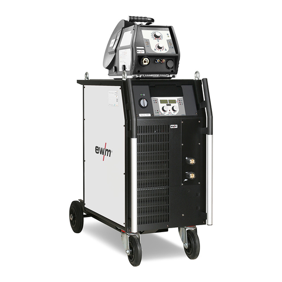
- Page 1 Operating instructions Welding machine Taurus 351, 401, 451, 551 Basic S FDG/FDW 099-005186-EW501 06.01.2012 Register now! For your benefit Jetzt Registrieren und Profitieren! www.ewm-group.com...
- Page 2 © EWM HIGHTEC WELDING GmbH · Dr. Günter-Henle-Str. 8 · D-56271 Mündersbach, Germany The copyright to this document remains the property of the manufacturer.
-
Page 3: Table Of Contents
Contents Notes on the use of these operating instructions Contents 1 Contents..............................3 2 Safety instructions..........................5 Notes on the use of these operating instructions ................5 Explanation of icons........................6 General ............................7 Transport and installation ......................11 2.4.1 Lifting by crane ......................12 Ambient conditions........................ - Page 4 Checklist for rectifying faults ......................35 Error messages (power source)....................36 Vent coolant circuit........................37 8 Technical data............................38 Taurus 401 Basic S........................38 Taurus 351, 451, 551 ........................39 9 Accessories ............................40 System components........................40 General accessories ........................40 Options ............................40 10 Appendix A............................41 10.1 Overview of EWM branches......................41 099-005186-EW501 06.01.2012...
-
Page 5: Safety Instructions
Safety instructions Notes on the use of these operating instructions Safety instructions Notes on the use of these operating instructions DANGER Working or operating procedures which must be closely observed to prevent imminent serious and even fatal injuries. • Safety notes include the "DANGER" keyword in the heading with a general warning symbol. •... -
Page 6: Explanation Of Icons
Safety instructions Explanation of icons Explanation of icons Symbol Description Press Do not press Turn Switch Switch off machine Switch on machine ENTER (enter the menu) NAVIGATION (Navigating in the menu) EXIT (Exit the menu) Time display (example: wait 4s/press) Interruption in the menu display (other setting options possible) Tool not required/do not use Tool required/use... -
Page 7: General
Safety instructions General General DANGER Electric shock! Welding machines use high voltages which can result in potentially fatal electric shocks and burns on contact. Even low voltages can cause you to get a shock and lead to accidents. • Do not touch any live parts in or on the machine! •... - Page 8 Safety instructions General WARNING Explosion risk! Apparently harmless substances in closed containers may generate excessive pressure when heated. • Move containers with inflammable or explosive liquids away from the working area! • Never heat explosive liquids, dusts or gases by welding or cutting! Smoke and gases! Smoke and gases can lead to breathing difficulties and poisoning.
- Page 9 Safety instructions General CAUTION Damage due to the use of non-genuine parts! The manufacturer's warranty becomes void if non-genuine parts are used! • Only use system components and options (power sources, welding torches, electrode holders, remote controls, spare parts and replacement parts, etc.) from our range of products! •...
- Page 10 Safety instructions General CAUTION EMC Machine Classification In accordance with IEC 60974-10, welding machines are grouped in two electromagnetic compatibility classes (see technical data): Class A machines are not intended for use in residential areas where the power supply comes from the low-voltage public mains network.
-
Page 11: Transport And Installation
Safety instructions Transport and installation Transport and installation WARNING Incorrect handling of shielding gas cylinders! Incorrect handling of shielding gas cylinders can result in serious and even fatal injury. • Observe the instructions from the gas manufacturer and in any relevant regulations concerning the use of compressed air! •... -
Page 12: Lifting By Crane
Safety instructions Transport and installation 2.4.1 Lifting by crane DANGER Risk of injury during lifting by crane! When lifting the equipment by crane, serious injuries can be inflicted by falling equipment or add-on units. • Transport on all lifting lugs at the same time (see Fig. -
Page 13: Ambient Conditions
Safety instructions Ambient conditions Ambient conditions CAUTION Installation site! The machine must not be operated in the open air and must only be set up and operated on a suitable, stable and level base! • The operator must ensure that the ground is non-slip and level, and provide sufficient lighting for the place of work. -
Page 14: Intended Use
Intended use Applications Intended use This machine has been manufactured according to the latest developments in technology and current regulations and standards. It must only be operated in line with the instructions on correct usage. WARNING Hazards due to improper usage! Hazards may arise for persons, animals and material objects if the equipment is not used correctly. -
Page 15: Use And Operation Solely With The Following Machines
Intended use Use and operation solely with the following machines Use and operation solely with the following machines NOTE A suitable wire feed unit (system component) is required in order to operate the welding machine! Taurus Basic S 351, 401, 451, 551 drive 200C WE drive 300C WE drive 4L... -
Page 16: Machine Description - Quick Overview
Machine description – quick overview Front view Machine description – quick overview Front view NOTE Coolant tank and quick connect coupling of coolant supply and return are only fitted in machines with water cooling. Figure 4-1 099-005186-EW501 06.01.2012... - Page 17 Machine description – quick overview Front view Item Symbol Description Lifting lug Ready for operation signal light Signal light on when the machine is switched on and ready for operation Main switch, machine on/off Carrying handle Cooling air inlet Wheels, guide castors Coolant tank Coolant tank cap Automatic cut-out of coolant pump key button...
-
Page 18: Rear View
Machine description – quick overview Rear view Rear view Figure 4-2 099-005186-EW501 06.01.2012... - Page 19 Machine description – quick overview Rear view Item Symbol Description 7-pole connection socket (digital) For connecting digital accessory components 7-pole connection socket (digital) Wire feed unit connection D-sub connection socket, 9-pole With this machine series for maintenance purposes only (specialist staff) Connection socket, "+"...
-
Page 20: Design And Function
Design and function General Design and function NOTE Observe documentation of other system components when connecting! General WARNING Risk of injury from electric shock! Contact with live parts, e.g. welding current sockets, is potentially fatal! • Follow safety instructions on the opening pages of the operating instructions. •... -
Page 21: Installation
Design and function Installation CAUTION Damage due to incorrect connection! Accessory components and the power source itself can be damaged by incorrect connection! • Only insert and lock accessory components into the relevant connection socket when the machine is switched off. •... -
Page 22: Machine Cooling
Design and function Machine cooling Machine cooling To obtain an optimal duty cycle from the power components, the following precautions should be observed: Ensure that the working area is adequately ventilated. • Do not obstruct the air inlets and outlets of the machine. •... -
Page 23: Welding Torch Cooling System
Design and function Welding torch cooling system Welding torch cooling system NOTE Only with water-cooled welding machines! 5.5.1 General CAUTION Coolant mixtures! Mixtures with other liquids or the use of unsuitable coolants result in material damage and renders the manufacturer's warranty void! •... -
Page 24: Adding Coolant
Design and function Welding torch cooling system 5.5.3 Adding coolant The unit is supplied ex works with a minimum level of coolant. Figure 5-1 Item Symbol Description Coolant tank cap Coolant filter sieve Coolant tank "Min" mark Minimum coolant level •... -
Page 25: Mains Connection
Design and function Mains connection Mains connection DANGER Hazard caused by improper mains connection! An improper mains connection can cause injuries or damage property! • Only use machine with a plug socket that has a correctly fitted protective conductor. • If a mains plug must be fitted, this may only be carried out by an electrician in accordance with the relevant national provisions or regulations (any phase sequence for three-phase machines)! -
Page 26: Shielding Gas Supply
Design and function Shielding gas supply Shielding gas supply 5.7.1 Connecting the shielding gas supply WARNING Risk of injury due to improper handling of shielding gas cylinders! Improper handling and insufficient securing of shielding gas cylinders can cause serious injuries! •... - Page 27 Design and function Shielding gas supply • Place the shielding gas cylinder into the relevant cylinder bracket. • Secure the shielding gas cylinder using a securing chain. Figure 5-3 Item Symbol Description Pressure regulator Shielding gas cylinder Output side of the pressure regulator Cylinder valve •...
-
Page 28: Intermediate Hose Package Connection
Design and function Intermediate hose package connection Intermediate hose package connection NOTE Note the polarity of the welding current! Some wire electrodes (e.g. self-shielding cored wire) are welded using negative polarity. In this case, the welding current lead should be connected to the "-" welding current socket, and the workpiece lead should be connected to the "+"... - Page 29 Design and function Intermediate hose package connection • Insert the end of the hose package through the strain relief of the hose package and lock by turning to the right. • Insert the plug on the welding current lead into the welding current connection socket "+" and lock. •...
-
Page 30: Mig/Mag Welding
Design and function MIG/MAG welding MIG/MAG welding 5.9.1 Connection for workpiece lead NOTE Note the polarity of the welding current! Some wire electrodes (e.g. self-shielding cored wire) are welded using negative polarity. In this case, the welding current lead should be connected to the "-" welding current socket, and the workpiece lead should be connected to the "+"... -
Page 31: Mma Welding
Design and function MMA welding 5.10 MMA welding CAUTION Risk of being crushed or burnt. When replacing spent or new stick electrodes • Switch off machine at the main switch • Wear appropriate safety gloves • Use insulated tongs to remove spent stick electrodes or to move welded workpieces and •... -
Page 32: Interfaces
Design and function Interfaces 5.11 Interfaces CAUTION Damage due to the use of non-genuine parts! The manufacturer's warranty becomes void if non-genuine parts are used! • Only use system components and options (power sources, welding torches, electrode holders, remote controls, spare parts and replacement parts, etc.) from our range of products! •... -
Page 33: Maintenance, Care And Disposal
Maintenance, care and disposal General Maintenance, care and disposal DANGER Risk of injury from electric shock! Cleaning machines that are not disconnected from the mains can lead to serious injuries! • Disconnect the machine completely from the mains. • Remove the mains plug! •... -
Page 34: Maintenance Work
Information about giving back used equipment or about collections can be obtained from the respective municipal administration office. • EWM participates in an approved waste disposal and recycling system and is registered in the Used Electrical Equipment Register (EAR) under number WEEE DE 57686922. •... -
Page 35: Rectifying Faults
Rectifying faults Checklist for rectifying faults Rectifying faults All products are subject to rigorous production checks and final checks. If, despite this, something fails to work at any time, please check the product using the following flowchart. If none of the fault rectification procedures described leads to the correct functioning of the product, please inform your authorised dealer. -
Page 36: Error Messages (Power Source)
Rectifying faults Error messages (power source) Error messages (power source) All products are subject to rigorous production checks and final checks. If, despite this, something fails to work at any time, please check the product using the following flowchart. If none of the fault rectification procedures described leads to the correct functioning of the product, please inform your authorised dealer. -
Page 37: Vent Coolant Circuit
Rectifying faults Vent coolant circuit Vent coolant circuit NOTE Coolant tank and quick connect coupling of coolant supply and return are only fitted in machines with water cooling. To vent the cooling system always use the blue coolant connection, which is located as deep as possible inside the system (close to the coolant tank)! 099-005186-EW501 06.01.2012... -
Page 38: Technical Data
Technical data Taurus 401 Basic S Technical data NOTE Performance specifications and guarantee only in connection with original spare and replacement parts! Taurus 401 Basic S MIG/MAG 5 A–400 A Setting range for welding current 20.2 V– 36.0 V 14.3 V–34.0 V Setting range for welding voltage 400 A Duty cycle at 40 °C (60% DC) -
Page 39: Taurus 351, 451, 551
Technical data Taurus 351, 451, 551 Taurus 351, 451, 551 Setting range welding current/voltage: 5 to 350 A 5 to 450 A 5 to 550 A 20.2 to 34.0 V 20.2 to 38 V 20.2 to 42 V MIG/MAG 5 to 350 A 5 to 450 A 5 to 550 A 14.3 to 31.5 V... -
Page 40: Accessories
Accessories System components Accessories NOTE Performance-dependent accessories like torches, workpiece leads, electrode holders or intermediate hose packages are available from your authorised dealer. System components Type Designation Item no. Taurus Basic S drive 4 WE Wire feed unit, water, Euro central connector 090-005198-00502 Taurus Basic S drive 4L WE Wire feed unit, water, Euro central connector... -
Page 41: Overview Of Ewm Branches
Appendix A Overview of EWM branches Appendix A 10.1 Overview of EWM branches 099-005186-EW501 06.01.2012...
Need help?
Do you have a question about the Taurus 451 Basic S FDG/FDW and is the answer not in the manual?
Questions and answers