Table of Contents
Advertisement
Advertisement
Table of Contents

Related Manuals for EWM Taurus 355 Synergic S TDM


Summary of Contents for EWM Taurus 355 Synergic S TDM
- Page 1 Operating instructions Welding machine Taurus 355 Synergic S TDM Taurus 405 Synergic S TDM Taurus 505 Synergic S TDM 099-005219-EW501 Observe additional system documents! 10.06.2013 Register now! For your benefit Jetzt Registrieren und Profitieren! www.ewm-group.com...
-
Page 2: General Instructions
© EWM HIGHTEC WELDING GmbH · Dr. Günter-Henle-Str. 8 · D-56271 Mündersbach, Germany The copyright to this document remains the property of the manufacturer. -
Page 3: Table Of Contents
Contents Notes on the use of these operating instructions Contents 1 Contents ..............................3 2 Safety instructions ..........................5 Notes on the use of these operating instructions ................5 Explanation of icons ........................6 General ............................7 Transport and installation ......................11 2.4.1 Ambient conditions ....................... - Page 4 Transport systems ........................47 Remote control / connection cable ....................47 General accessories ........................48 Computer communication ......................48 10 Appendix A ............................49 10.1 JOB-List............................49 11 Appendix B ............................50 11.1 Overview of EWM branches......................50 099-005219-EW501 10.06.2013...
-
Page 5: Safety Instructions
Safety instructions Notes on the use of these operating instructions Safety instructions Notes on the use of these operating instructions DANGER Working or operating procedures which must be closely observed to prevent imminent serious and even fatal injuries. • Safety notes include the "DANGER" keyword in the heading with a general warning symbol. •... -
Page 6: Explanation Of Icons
Safety instructions Explanation of icons Explanation of icons Symbol Description Press Do not press Turn Switch Switch off machine Switch on machine ENTER ENTER (enter the menu) ENTER NAVIGATION NAVIGATION (Navigating in the menu) EXIT EXIT (Exit the menu) Time display (example: wait 4s/press) Interruption in the menu display (other setting options possible) Tool not required/do not use Tool required/use... -
Page 7: General
Safety instructions General General DANGER Electromagnetic fields! The power source may cause electrical or electromagnetic fields to be produced which could affect the correct functioning of electronic equipment such as IT or CNC devices, telecommunication lines, power cables, signal lines and pacemakers. •... - Page 8 Safety instructions General WARNING Smoke and gases! Smoke and gases can lead to breathing difficulties and poisoning. In addition, solvent vapour (chlorinated hydrocarbon) may be converted into poisonous phosgene due to the ultraviolet radiation of the arc! • Ensure that there is sufficient fresh air! •...
- Page 9 Safety instructions General CAUTION Obligations of the operator! The respective national directives and laws must be observed for operation of the machine! • National implementation of the framework directive (89/391/EWG), as well as the associated individual directives. • In particular, directive (89/655/EWG), on the minimum regulations for safety and health protection when staff members use equipment during work.
- Page 10 Safety instructions General CAUTION EMC Machine Classification In accordance with IEC 60974-10, welding machines are grouped in two electromagnetic compatibility classes (see technical data): Class A machines are not intended for use in residential areas where the power supply comes from the low-voltage public mains network.
-
Page 11: Transport And Installation
Safety instructions Transport and installation Transport and installation WARNING Incorrect handling of shielding gas cylinders! Incorrect handling of shielding gas cylinders can result in serious and even fatal injury. • Observe the instructions from the gas manufacturer and in any relevant regulations concerning the use of compressed air! •... -
Page 12: Ambient Conditions
Safety instructions Transport and installation 2.4.1 Ambient conditions CAUTION Installation site! The machine must not be operated in the open air and must only be set up and operated on a suitable, stable and level base! • The operator must ensure that the ground is non-slip and level, and provide sufficient lighting for the place of work. -
Page 13: Intended Use
Intended use Use and operation solely with the following machines Intended use This machine has been manufactured according to the latest developments in technology and current regulations and standards. It must only be operated in line with the instructions on correct usage. WARNING Hazards due to improper usage! Hazards may arise for persons, animals and material objects if the equipment is not... -
Page 14: Applications
Intended use Applications Applications 3.2.1 MIG/MAG standard welding Metal arc welding using a wire electrode whereby gas from an external source surrounds the arc and the molten pool to protect them from the atmosphere. 3.2.1.1 forceArc Welding with a powerful forced arc, deep fusion penetration and virtually spatter-free weld seams of the highest quality. -
Page 15: Documents Which Also Apply
Intended use Documents which also apply Documents which also apply 3.3.1 Warranty NOTE For further information, please see the accompanying supplementary sheets "Machine and Company Data, Maintenance and Testing, Warranty"! 3.3.2 Declaration of Conformity The designated machine conforms to EC Directives and standards in terms of its design and construction: •... -
Page 16: Machine Description - Quick Overview
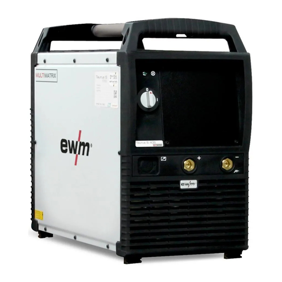
Machine description – quick overview Front view Machine description – quick overview NOTE The maximum possible machine configuration is given in the text description. If necessary, the optional connection may need to be retrofitted (see "Accessories" chapter). Front view Figure 4-1 099-005219-EW501 10.06.2013... - Page 17 Machine description – quick overview Front view Item Symbol Description Carrying handle Ready for operation signal light Signal light on when the machine is switched on and ready for operation Main switch, machine on/off Cooling air inlet Machine feet Connection socket, "+" welding current •...
-
Page 18: Rear View
Machine description – quick overview Rear view Rear view Figure 4-2 099-005219-EW501 10.06.2013... - Page 19 Machine description – quick overview Rear view Item Symbol Description Key button, Automatic cutout Wire feed motor supply voltage fuse (press to reset a triggered fuse) Connection socket, 7-pole Connection for peripheral devices with digital interface 7-pole connection socket (digital) Wire feed unit connection Connection socket, “+”...
-
Page 20: Design And Function
Design and function General Design and function General WARNING Risk of injury from electric shock! Contact with live parts, e.g. welding current sockets, is potentially fatal! • Follow safety instructions on the opening pages of the operating instructions. • Commissioning may only be carried out by persons who have the relevant expertise of working with arc welding machines! •... -
Page 21: Machine Cooling
Design and function Machine cooling CAUTION Using protective dust caps! Protective dust caps protect the connection sockets and therefore the machine against dirt and damage. • The protective dust cap must be fitted if there is no accessory component being operated on that connection. -
Page 22: Installation
Design and function Installation Installation WARNING Risk of accident due to improper transport of machines that may not be lifted! Do not lift or suspend the machine! The machine can fall down and cause injuries! The handles and brackets are suitable for transport by hand only! •... -
Page 23: Notes On The Installation Of Welding Current Leads
Design and function Notes on the installation of welding current leads Notes on the installation of welding current leads NOTE Incorrectly installed welding current leads can cause faults in the arc (flickering). Install welding lead and hose package in parallel and as close together as possible. Keep the welding lead and hose packages of each welding machine separate, with an installation distance of at least 15 cm! Fully unroll welding current leads, torch hose packages and intermediate hose... -
Page 24: Welding Torch Cooling System
Design and function Welding torch cooling system Welding torch cooling system 5.6.1 Cooling module connection NOTE Observe the fitting and connection instructions given in the relevant operating instructions for the cooling unit. Figure 5-2 Item Symbol Description 4-pole connection socket Cooling unit voltage supply 8-pole connection socket Cooling unit control lead... -
Page 25: Mains Connection
Design and function Mains connection Mains connection DANGER Hazard caused by improper mains connection! An improper mains connection can cause injuries or damage property! • Only use machine with a plug socket that has a correctly fitted protective conductor. • If a mains plug must be fitted, this may only be carried out by an electrician in accordance with the relevant national provisions or regulations! •... -
Page 26: Connecting The Intermediate Hose Package To The Power Source
Design and function Connecting the intermediate hose package to the power source Connecting the intermediate hose package to the power source 5.8.1 Intermediate hose package strain relief CAUTION Missing or incorrectly fitted strain relief! Connection sockets or connection plugs on the machine, or the intermediate tube package, may be damaged if the strain relief is missing or incorrectly fitted. -
Page 27: Intermediate Hose Package Connection
Design and function Connecting the intermediate hose package to the power source 5.8.2 Intermediate hose package connection NOTE Note the polarity of the welding current! Some wire electrodes (e.g. self-shielding cored wire) are welded using negative polarity. In this case, the welding current lead should be connected to the "-" welding current socket, and the workpiece lead should be connected to the "+"... -
Page 28: Shielding Gas Supply (Shielding Gas Cylinder For Welding Machine)
Design and function Shielding gas supply (shielding gas cylinder for welding machine) Shielding gas supply (shielding gas cylinder for welding machine) WARNING Risk of injury due to improper handling of shielding gas cylinders! Improper handling and insufficient securing of shielding gas cylinders can cause serious injuries! •... -
Page 29: Welding Torch Holder
Design and function Welding torch holder 5.10 Welding torch holder NOTE The item described in the following is part of the machine´s scope of delivery. Figure 5-7 Item Symbol Description Crossmember of the transport handle Torch holder Fan-type lock washers Fixing screws (x 4) •... -
Page 30: Mig/Mag Welding
Design and function MIG/MAG welding 5.11 MIG/MAG welding 5.11.1 Connection for workpiece lead NOTE Note the polarity of the welding current! Some wire electrodes (e.g. self-shielding cored wire) are welded using negative polarity. In this case, the welding current lead should be connected to the "-" welding current socket, and the workpiece lead should be connected to the "+"... -
Page 31: Tig Welding
Design and function TIG welding 5.12 TIG welding 5.12.1 Welding torch connection NOTE The welding torch is connected to the wire feeder. Observe the operating instructions for the wire feeder (system component)! 5.12.2 Connection for workpiece lead Figure 5-9 Item Symbol Description Workpiece Connection socket, "+"... -
Page 32: Mma Welding
Design and function MMA welding 5.13 MMA welding CAUTION Risk of being crushed or burnt. When replacing spent or new stick electrodes • Switch off machine at the main switch • Wear appropriate safety gloves • Use insulated tongs to remove spent stick electrodes or to move welded workpieces and •... -
Page 33: Remote Control
Design and function Remote control 5.14 Remote control CAUTION Damage to the machine due to improper connection! The remote controls have been developed to be connected to welding machines or wire feed units only. Connecting them to other machines may cause damage to the machines! •... -
Page 34: Interfaces
Design and function Interfaces 5.15 Interfaces 5.15.1 PC Interfaces CAUTION Damage due to the use of non-genuine parts! The manufacturer's warranty becomes void if non-genuine parts are used! • Only use system components and options (power sources, welding torches, electrode holders, remote controls, spare parts and replacement parts, etc.) from our range of products! •... -
Page 35: Maintenance, Care And Disposal
Maintenance, care and disposal General Maintenance, care and disposal DANGER Risk of injury from electric shock! Cleaning machines that are not disconnected from the mains can lead to serious injuries! • Disconnect the machine completely from the mains. • Remove the mains plug! •... -
Page 36: Monthly Maintenance Tasks
Maintenance, care and disposal Maintenance work 6.2.2 Monthly maintenance tasks 6.2.2.1 Visual inspection • Casing damage (front, rear and side walls) • Wheels and their securing elements • Transport elements (strap, lifting lugs, handle) • Check coolant tubes and their connections for impurities 6.2.2.2 Functional test •... -
Page 37: Disposing Of Equipment
Information about giving back used equipment or about collections can be obtained from the respective municipal administration office. • EWM participates in an approved waste disposal and recycling system and is registered in the Used Electrical Equipment Register (EAR) under number WEEE DE 57686922. •... -
Page 38: Rectifying Faults
Rectifying faults Checklist for rectifying faults Rectifying faults All products are subject to rigorous production checks and final checks. If, despite this, something fails to work at any time, please check the product using the following flowchart. If none of the fault rectification procedures described leads to the correct functioning of the product, please inform your authorised dealer. -
Page 39: Error Messages (Power Source)
Rectifying faults Error messages (power source) Error messages (power source) NOTE A welding machine error is indicated by an error code being displayed (see table) on the display on the machine control. In the event of a machine error, the power unit is shut down. The display of possible error numbers depends on the machine version (interfaces/functions). - Page 40 Rectifying faults Error messages (power source) Legend for categories (error reset) a) The error message will disappear once the error has been rectified. b) The error message can be reset by pressing a key button: Welding machine control Key button RC1 / RC2 Expert CarExpert / Progress (M3.11)
-
Page 41: Resetting Jobs (Welding Tasks) To The Factory Settings
Rectifying faults Resetting JOBs (welding tasks) to the factory settings Resetting JOBs (welding tasks) to the factory settings 7.3.1 Resetting a single JOB RESET ENTER JOB- JOB- LIST LIST EXIT m /m in Figure 7-1 Display Setting/selection Reset to factory settings The RESET will be done after pressing the button. -
Page 42: Resetting All Jobs
Rectifying faults Resetting JOBs (welding tasks) to the factory settings 7.3.2 Resetting all JOBs NOTE All customised welding parameters that are stored will be replaced by the factory settings. RESET ENTER JOB- JOB- LIST LIST EXIT m /m in Figure 7-2 Display Setting/selection Reset to factory settings... -
Page 43: Vent Coolant Circuit
Rectifying faults Vent coolant circuit Vent coolant circuit NOTE Coolant tank and quick connect coupling of coolant supply and return are only fitted in machines with water cooling. To vent the cooling system always use the blue coolant connection, which is located as deep as possible inside the system (close to the coolant tank)! Figure 7-3 099-005219-EW501... -
Page 44: Technical Data
Technical data Taurus 355 TDM Technical data NOTE Performance specifications and guarantee only in connection with original spare and replacement parts! Taurus 355 TDM MIG/MAG Setting range for welding current 5 A–350 A Setting range for welding voltage 14,3 V - 31,5 V 10,2 V - 24,0 V 20,2 V - 34,0 V Duty cycle... -
Page 45: Taurus 405 Tdm
Technical data Taurus 405 TDM Taurus 405 TDM MIG/MAG Setting range for welding current 5 A–400 A Setting range for welding voltage 10.2 V–26.0 V 14.3 V–34.0 V 20.2 V–36.0 V Duty cycle 40 °C 100% 400 A ∧ Load alternation 10 min. -
Page 46: Taurus 505 Tdm
Technical data Taurus 505 TDM Taurus 505 TDM MIG/MAG Setting range for welding current 5 A–500 A Setting range for welding voltage 10.2 V–32.0 V 14.3 V–39.0 V 20.2 V–40.0 V Duty cycle 40 °C 25 °C 40 °C 25 °C 40 °C 25 °C 60 %... -
Page 47: Accessories
Accessories System components Accessories NOTE Performance-dependent accessories like torches, workpiece leads, electrode holders or intermediate hose packages are available from your authorised dealer. System components Type Designation Item no. Taurus Synergic S drive 4L Wire feed unit, water, Euro central connector 090-005201-00502 Taurus Synergic S drive 4 WE Wire feed unit, water, Euro central connector 090-005199-00502... -
Page 48: General Accessories
Accessories General accessories General accessories Type Designation Item no. 5POLE/CEE/32A/M Machine plug 094-000207-00000 DM1 35L/MIN Manometer pressure regulator 094-000009-00000 Computer communication Type Designation Item no. PC300.Net PC300.Net welding parameter software kit incl. 090-008777-00000 cable and SECINT X10 USB interface CD PC300.Net update PC300.Net Update on CD-ROM 092-008172-00001 FRV 7POL 5 m... -
Page 49: Job-List
Appendix A JOB-List Appendix A 10.1 JOB-List Figure 10-1 099-005219-EW501 10.06.2013... -
Page 50: Overview Of Ewm Branches
Appendix B Overview of EWM branches Appendix B 11.1 Overview of EWM branches 099-005219-EW501 10.06.2013...
Need help?
Do you have a question about the Taurus 355 Synergic S TDM and is the answer not in the manual?
Questions and answers