
Related Manuals for EWM Picomig 355 puls TKM


Summary of Contents for EWM Picomig 355 puls TKM
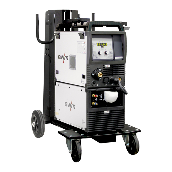
- Page 1 Operating instructions Welding machine Picomig 355 puls TKM 099-005542-EW501 Observe additional system documents! 24.03.2020...
- Page 2 +49 2680 181-0. A list of authorised sales partners can be found at www.ewm-group.com/en/specialist-dealers. Liability relating to the operation of this equipment is restricted solely to the function of the equipment. No other form of liability, regardless of type, shall be accepted.
-
Page 3: Table Of Contents
Contents Notes on using these operating instructions Contents 1 Contents ..............................3 2 For your safety ............................7 Notes on using these operating instructions .................. 7 Explanation of icons ........................8 Part of the complete documentation ....................9 Safety instructions ........................10 Transport and installation ...................... - Page 4 7.5.1 Resetting a single JOB ....................69 7.5.2 Resetting all JOBs ......................69 8 Technical data............................70 Picomig 355 puls TKM ......................... 70 9 Accessories ............................71 9.1.1 Welding torch cooling system ..................71 Transport systems ........................71 Remote control/connecting and extension cable ................. 71 9.3.1...
- Page 5 Contents Notes on using these operating instructions General accessories ........................72 10 Replaceable parts ..........................73 10.1 Wire feed rollers ........................... 73 10.1.1 Wire feed rollers for steel wire ..................73 10.1.2 Wire feed rollers for aluminium wire ................73 10.1.3 Wire feed rollers for cored wire ..................
- Page 6 Contents Notes on using these operating instructions 099-005542-EW501 24.03.2020...
-
Page 7: For Your Safety
For your safety Notes on using these operating instructions For your safety Notes on using these operating instructions DANGER Working or operating procedures which must be closely observed to prevent imminent serious and even fatal injuries. • Safety notes include the "DANGER" keyword in the heading with a general warning symbol. •... -
Page 8: Explanation Of Icons
For your safety Explanation of icons Explanation of icons Symbol Description Symbol Description Indicates technical aspects which the Activate and release / Tap / Tip user must observe. Switch off machine Release Switch on machine Press and hold Switch Incorrect / Invalid Turn Correct / Valid Numerical value –... -
Page 9: Part Of The Complete Documentation
For your safety Part of the complete documentation Part of the complete documentation This document is part of the complete documentation and valid only in combination with all other parts of these instructions! Read and observe the operating instructions for all system components, especially the safety instructions! The illustration shows a general example of a welding system. -
Page 10: Safety Instructions
For your safety Safety instructions Safety instructions WARNING Risk of accidents due to non-compliance with the safety instructions! Non-compliance with the safety instructions can be fatal! • Carefully read the safety instructions in this manual! • Observe the accident prevention regulations and any regional regulations! •... - Page 11 For your safety Safety instructions WARNING Explosion risk! Apparently harmless substances in closed containers may generate excessive pressure when heated. • Move containers with inflammable or explosive liquids away from the working area! • Never heat explosive liquids, dusts or gases by welding or cutting! Fire hazard! Due to the high temperatures, sparks, glowing parts and hot slag that occur during welding, there is a risk of flames.
- Page 12 For your safety Safety instructions CAUTION According to IEC 60974-10, welding machines are divided into two classes of electromagnetic compatibility (the EMC class can be found in the Technical da- ta) > see 8 chapter: Class A machines are not intended for use in residential areas where the power supply comes from the low-voltage public mains network.
-
Page 13: Transport And Installation
For your safety Transport and installation The manufacturer's warranty becomes void if non-genuine parts are used! • Only use system components and options (power sources, welding torches, electrode hold- ers, remote controls, spare parts and replacement parts, etc.) from our range of products! •... - Page 14 For your safety Transport and installation The units are designed for operation in an upright position! Operation in non-permissible positions can cause equipment damage. • Only transport and operate in an upright position! Accessory components and the power source itself can be damaged by incorrect connection! •...
-
Page 15: Intended Use
3.2.1 Warranty For more information refer to the "Warranty registration" brochure supplied and our information regarding warranty, maintenance and testing at www.ewm-group.com! 3.2.2 Declaration of Conformity This product corresponds in its design and construction to the EU directives listed in the decla- ration. -
Page 16: Machine Description - Quick Overview
Machine description – quick overview Front view / rear view Machine description – quick overview Front view / rear view Figure 4-1 099-005542-EW501 24.03.2020... - Page 17 Machine description – quick overview Front view / rear view Item Symbol Description Carrying handle Machine control > see 4.3 chapter 19-pole connection socket (analogue) For connecting analogue accessory components (remote control, welding torch control lead, etc.) Welding torch connection (Euro or Dinse torch connector) Welding current, shielding gas and torch trigger integrated Park socket, polarity selection plug Retainer for the polarity selection plug in MMA mode or for transport.
-
Page 18: Inside View
Machine description – quick overview Inside view Inside view Figure 4-2 099-005542-EW501 24.03.2020... - Page 19 Machine description – quick overview Inside view Item Symbol Description Slide latch, lock for the protective cap Wire spool inspection window Check wire supply Protective cap Cover for the wire feed mechanism and other operating elements. Depending on the machine series, additional stickers with information on the replace- ment parts and JOB lists will be located on the inside.
-
Page 20: Machine Control - Operating Elements
Machine description – quick overview Machine control – Operating elements Machine control – Operating elements Figure 4-3 Item Symbol Description “Collective interference” signal light “Excess temperature” signal light Welding data display (3-digit) Displays the welding parameters and the corresponding values > see 4.3.1 chapter Welding parameter display mode/power-saving mode push-button --------- Welding current --------- Material thickness... - Page 21 Machine description – quick overview Machine control – Operating elements Item Symbol Description Operating mode button --------- Non-latched ------- Latched ----- Spots ----- Interval Runtime parameters button For selecting the parameters to be set. Also for entering and exiting the menus for ad- vanced settings.
-
Page 22: Welding Data Display
Machine description – quick overview Machine control – Operating elements 4.3.1 Welding data display Figure 4-4 The push-button for the welding parameter display mode is next to the display. Each time the push-button is pressed the display changes to the next parameter. After the last parameter is reached the display continues with the first parameter. -
Page 23: Design And Function
Design and function Transport and installation Design and function WARNING Risk of injury from electrical voltage! Contact with live parts, e.g. power connections, can be fatal! • Observe the safety information on the first pages of the operating instructions! • Commissioning must be carried out by persons who are specifically trained in handling power sources! •... -
Page 24: Machine Cooling
Design and function Transport and installation 5.1.2 Machine cooling Insufficient ventilation results in a reduction in performance and equipment damage. • Observe the ambient conditions! • Keep the cooling air inlet and outlet clear! • Observe the minimum distance of 0.5 m from obstacles! 5.1.3 Workpiece lead, general CAUTION... -
Page 25: Notes On The Installation Of Welding Current Leads
Design and function Transport and installation 5.1.5 Notes on the installation of welding current leads • Incorrectly installed welding current leads can cause faults in the arc (flickering). • Lay the workpiece lead and hose package of power sources without HF igniter (MIG/MAG) for as long and as close as possible in parallel. -
Page 26: Stray Welding Currents
Design and function Transport and installation 5.1.6 Stray welding currents WARNING Risk of injury due to stray welding currents! Stray welding currents can destroy protective earth conductors, damage machines and electronic devices and cause overheating of components, leading to fire. •... -
Page 27: Mains Connection
Design and function Transport and installation 5.1.7 Mains connection DANGER Hazards caused by improper mains connection! An improper mains connection can cause injuries or damage property! • The connection (mains plug or cable), the repair or voltage adjustment of the device must be carried out by a qualified electrician in accordance with the respective local laws or nati- onal regulations! •... -
Page 28: Welding Torch Holder
Design and function Transport and installation 5.1.8 Welding torch holder The item described in the following is part of the machine´s scope of delivery. Figure 5-7 Item Symbol Description Crossmember of the transport handle Torch holder Fixing screws (x 4) Fan-type lock washers •... -
Page 29: Shielding Gas Supply (Shielding Gas Cylinder For Welding Machine)
Design and function Transport and installation 5.1.9 Shielding gas supply (shielding gas cylinder for welding machine) WARNING Risk of injury due to improper handling of shielding gas cylinders! Improper handling and insufficient securing of shielding gas cylinders can cause serious injuries! •... -
Page 30: Shielding Gas Hose Connection
Design and function Transport and installation 5.1.9.2 Shielding gas hose connection Figure 5-9 Item Symbol Description Shielding gas cylinder / pressure regulator Connection thread - G¼" Shielding gas connection (inlet) • Screw the gas hose connection to the shielding gas connection (inlet) on the machine gas-tight. 5.1.10 Shielding gas volume settings If the shielding gas setting is too low or too high, this can introduce air to the weld pool and may cause pores to form. -
Page 31: 5.1.10.1 Gas Test
Design and function MIG/MAG welding 5.1.10.1 Gas test Figure 5-10 5.1.10.2 Purge hose package 300s Figure 5-11 MIG/MAG welding 5.2.1 Welding torch and workpiece line connection On delivery, the Euro torch connector is fitted with a capillary tube for welding torches with a steel liner. Conversion is necessary if a welding torch with a liner is used! •... - Page 32 Design and function MIG/MAG welding Figure 5-12 Item Symbol Description Welding torch Polarity selector plug, welding current cable Internal welding current cable for central connection/welding torch. • ---------- Connection socket for “+” welding current Workpiece • Insert the polarity selection plug into the "+" welding current connection socket and lock in place by turning to the right.
-
Page 33: Mig/Mag Function Torch
Design and function MIG/MAG welding 5.2.2 MIG/MAG function torch The torch trigger on the MIG welding torch is generally used to start and finish the welding process. Func- tion torches feature additional operating elements to set the wire feed speed and voltage correction. Welding torches with one rotary knob, one rocker or one pair of buttons only must be configured on the machine control appropriately. -
Page 34: Inserting The Wire Spool
Design and function MIG/MAG welding 5.2.4.1 Inserting the wire spool CAUTION Risk of injury due to incorrectly secured wire spool. If the wire spool is not secured properly, it may come loose from the wire spool support and fall to the ground, causing damage to the machine and injuries. •... -
Page 35: Changing The Wire Feed Rollers
Design and function MIG/MAG welding 5.2.4.2 Changing the wire feed rollers Figure 5-16 Item Symbol Description Tommy The tommy is used to secure the closure brackets of the wire feed rollers. Closure bracket The closure brackets are used to secure the wire feed rollers. Feed roll tensioner Fixing the clamping unit and setting the pressure. - Page 36 Design and function MIG/MAG welding Unsatisfactory welding results due to faulty wire feeding! The wire feed rolls must be suitable for the diameter of the wire and the material. The wire feed rolls are colour-coded to facilitate distinction (see the Wire feed roll overview table). When working with a wire diameter of >...
-
Page 37: Inching The Wire Electrode
Design and function MIG/MAG welding 5.2.4.3 Inching the wire electrode CAUTION Risk of injury due to welding wire escaping from the welding torch! The welding wire can escape from the welding torch at high speed and cause bodily injury including injuries to the face and eyes! •... -
Page 38: Spool Brake Setting
Design and function MIG/MAG welding A prerequisite for the automatic inching process is the correct preparation of the wire guide, especially in the capillary and wire guide tube area > see 5.4.2 chapter. • The contact pressure has to be adjusted separately for each side (wire inlet/outlet) at the feed roll ten- sioner setting nuts depending on the welding consumable used. -
Page 39: Welding Task Selection
Design and function MIG/MAG welding 5.2.6 Welding task selection The settings for the respective welding parameters are defined by the different JOBs. The right JOB can be determined quickly with the JOB list > see 11.1 chapter. Figure 5-20 Validity of the settings. Spot time, pause time and wire feed speed settings apply to all JOBs. -
Page 40: Operating Point Setting Using Material Thickness
Design and function MIG/MAG welding 5.2.7.2 Operating point setting using material thickness Automatic display mode switching: If the wire speed or the voltage is changed, the display will switch briefly to show the respective parameter. This means that you don't have to change the display mode before setting the parameter. -
Page 41: Rootarc/Rootarc Puls
Design and function MIG/MAG welding 5.2.9 rootArc/rootArc puls Short arc with perfect weld modelling capabilities for effortless gap bridging, especially for root welding Figure 5-25 • Reduced spatter compared to standard short arc • Good root formation and secure sidewall fusion •... - Page 42 Design and function MIG/MAG welding Non-latched mode Figure 5-26 Step 1 • Press and hold torch trigger. • Shielding gas is expelled (gas pre-flows). • Wire feed motor runs at “creep speed”. • Arc ignites after the wire electrode makes contact with the workpiece; welding current flows. •...
- Page 43 Design and function MIG/MAG welding Latched mode Figure 5-27 1. cycle • Press and hold torch trigger • Shielding gas is expelled (gas pre-flows) • Wire feed motor runs at “creep speed” • Arc ignites when the wire electrode makes contact with the workpiece Welding current flows •...
- Page 44 Design and function MIG/MAG welding Spot welding Figure 5-28 Start • Press and hold torch trigger. • Shielding gas is expelled (gas pre-flows). • Arc ignites after the wire electrode makes contact with the workpiece at creep speed. • Welding current flows. •...
-
Page 45: Conventional Mig/Mag Welding (Gmaw Non Synergic)
Design and function MIG/MAG welding Interval Figure 5-29 Start • Press and hold torch trigger. • Shielding gas is expelled (gas pre-flows). Sequence • Arc ignites after the wire electrode makes contact with the workpiece at creep speed. • Welding current flows. •... -
Page 46: Expert Menu (Mig/Mag)
Design and function MIG/MAG welding 5.2.12 Expert menu (MIG/MAG) The Expert menu has adjustable parameters stored that don’t require regular setting. The number of pa- rameters shown may be limited, e.g. if a function is deactivated. Figure 5-31 Display Setting/selection Gas pre-flow time Burn-back correction 099-005542-EW501... -
Page 47: Mma Welding
Design and function MMA welding MMA welding 5.3.1 Connecting the electrode holder and workpiece lead CAUTION Risk of crushing and burns! When changing stick electrodes there is a risk of crushing and burns! • Wear appropriate and dry protective gloves. •... -
Page 48: Welding Task Selection
Design and function MMA welding 5.3.2 Welding task selection • Select MMA JOB 128 > see 11.1 chapter. You can only change the JOB number when no welding current is flowing. Figure 5-33 5.3.3 Arcforce During the welding process, arcforce prevents the electrode sticking in the weld pool with increases in current. -
Page 49: Antistick
Design and function MMA welding 5.3.5 Antistick The Antistick feature prevents the electrode from annealing. Should the electrode stick despite the Arcforce feature, the machine automatically switches to the minimum current within approx. one se- cond. This prevents the electrode from annealing. Check the welding current setting and correct for the welding task in hand. -
Page 50: Tig Welding
Design and function TIG welding TIG welding 5.4.1 Preparing the TIG welding torch The TIG welding torch is to be equipped to suit the relevant welding task! • Fit suitable tungsten electrodes and • an appropriate shielding gas nozzle. • Observe the operating instructions for the TIG welding torch! 5.4.2 Welding torch and workpiece line connection... -
Page 51: Welding Task Selection
Design and function TIG welding 5.4.3 Welding task selection • Select TIG JOB 127. You can only change the JOB number when no welding current is flowing. Figure 5-39 5.4.4 Adjusting the gas post-flow time Figure 5-40 Display Setting/selection Gas post-flow time 099-005542-EW501 24.03.2020... -
Page 52: Expert Menu (Tig)
Design and function TIG welding 5.4.5 Expert menu (TIG) The Expert menu has adjustable parameters stored that don’t require regular setting. The number of pa- rameters shown may be limited, e.g. if a function is deactivated. Figure 5-41 Display Setting/selection Gas pre-flow time Ignition current (as percentage, dependent on main current) Upslope time to main current... -
Page 53: Arc Ignition
Design and function TIG welding 5.4.6 Arc ignition 5.4.6.1 Liftarc Figure 5-42 The arc ignites through contact with the workpiece: a) Carefully place the torch gas nozzle and tungsten electrode tip against the workpiece (lift arc current flows independent of the set main current) b) Angle the torch above the torch gas nozzle until the distance between electrode tip and workpiece is approx. - Page 54 Design and function TIG welding Non-latched mode Figure 5-43 1st cycle • Press and hold torch trigger. • Shielding gas is expelled (gas pre-flows). The arc is ignited using liftarc. • The welding current flows with the value set for the starting current I start •...
-
Page 55: Remote Control
Design and function Remote control Latched mode Figure 5-44 1st cycle • Press and hold torch trigger. • Shielding gas is expelled (gas pre-flows). The arc is ignited using liftarc. • The welding current flows with the value set for the starting current I start 2nd cycle •... -
Page 56: Selecting, Changing And Saving Parameters
Design and function Special parameters (advanced settings) 5.6.1 Selecting, changing and saving parameters Figure 5-45 Display Setting/selection Wire inching / wire return ramp time 0 = ------- normal inching (10 s ramp time) 1 = ------- fast inching (3 s ramp time) (ex works) Lat. -
Page 57: Reset To Factory Settings
Design and function Special parameters (advanced settings) 5.6.3 Reset to factory settings All special parameters saved by the user will be overwritten by the factory settings! Figure 5-46 099-005542-EW501 24.03.2020... -
Page 58: Machine Configuration Menu
Design and function Machine configuration menu Machine configuration menu 5.7.1 Selecting, changing and saving parameters Figure 5-47 Display Setting/selection Lead resistance 1 Lead resistance for the first welding circuit 0 mΩ–60 mΩ (8 mΩ ex works). Time-based power-saving mode > see 5.8 chapter Time to activation of the power-saving mode in case of inactivity. -
Page 59: Aligning The Cable Resistance
Design and function Machine configuration menu 5.7.2 Aligning the cable resistance The resistance value of cables can either be set directly or it can be aligned using the power source. The factory setting of the power sources is 8 mΩ. This value correponds to a 5 m earth cable, a 1.5 m inter- mediate hose package and a 3 m water-cooled welding torch. -
Page 60: Power-Saving Mode (Standby)
Design and function Power-saving mode (Standby) 1 Preparation • Switch off the welding machine. • Unscrew the gas nozzle from the welding torch. • Trim the welding wire so that it is flush with the contact tip. • Retract the welding wire a little (approx. 50 mm) on the wire feeder. There should now be no more welding wire in the contact tip. -
Page 61: Maintenance, Care And Disposal
Maintenance, care and disposal General Maintenance, care and disposal General DANGER Risk of injury due to electrical voltage after switching off! Working on an open machine can lead to fatal injuries! Capacitors are loaded with electrical voltage during operation. Voltage remains present for up to four minutes after the mains plug is removed. -
Page 62: Maintenance Work, Intervals
A periodic test according to IEC 60974-4 "Periodic inspection and test" has to be carried out. In addition to the regulations on testing given here, the relevant local laws and regulations must also be observed. For more information refer to the "Warranty registration" brochure supplied and our information regarding warranty, maintenance and testing at www.ewm-group.com! 099-005542-EW501 24.03.2020... -
Page 63: Disposing Of Equipment
• Information about returning used equipment or about collections can be obtained from the respective municipal administration office. • In addition to this, returns are also possible throughout Europe via EWM sales partners. 099-005542-EW501 24.03.2020... -
Page 64: Rectifying Faults
Rectifying faults Checklist for rectifying faults Rectifying faults All products are subject to rigorous production checks and final checks. If, despite this, something fails to work at any time, please check the product using the following flowchart. If none of the fault rectification procedures described leads to the correct functioning of the product, please inform your authorised dea- ler. -
Page 65: Error Messages (Power Source)
Rectifying faults Error messages (power source) Mains fuse triggers Mains fuse triggers - unsuitable mains fuse Set up recommended mains fuse > see 8 chapter. Error messages (power source) Depending on the options of the machine display, a fault is shown as follows: Display type - machine control Display Graphic display... - Page 66 Rectifying faults Error messages (power source) Category Possible cause Remedy Detection of wire feeder 2 Check cable connections Error in open circuit voltage Inform Service. reduction (VRD) Overcurrent detection on wire Check ease of wire feeding feeder Error in tachometer generator Check the connection and particularly the signal tachometer generator of the second wire...
-
Page 67: Welding Parameter Calibration
Rectifying faults Welding parameter calibration Welding parameter calibration In case of deviations between the welding parameters set on the front panel/remote control and those shown on the welding machine, this function allows for easy alignment. Figure 7-1 099-005542-EW501 24.03.2020... -
Page 68: Resetting Welding Parameters To The Factory Settings
Rectifying faults Resetting welding parameters to the factory settings Resetting welding parameters to the factory settings RESET Figure 7-2 Display Setting/selection Code of machine control Initialisation complete All customised welding parameters haven been overwritten by the factory settings. 099-005542-EW501 24.03.2020... -
Page 69: Resetting Jobs (Welding Tasks) To The Factory Settings
Rectifying faults Resetting JOBs (welding tasks) to the factory settings Resetting JOBs (welding tasks) to the factory settings 7.5.1 Resetting a single JOB Figure 7-3 Display Setting/selection RESET to factory settings The RESET will be done after pressing the button. The menu will be ended when no changes are done after 3 sec. -
Page 70: Technical Data
Technical data Picomig 355 puls TKM Technical data Picomig 355 puls TKM Performance specifications and guarantee only in connection with original spare and replacement parts! MIG/MAG Welding current (I 5 A to 350 A Welding voltage according to stan- 14,3 V to 31,5 V... -
Page 71: Accessories
Accessories Transport systems Accessories Performance-dependent accessories like torches, workpiece leads, electrode holders or intermediate hose packages are available from your authorised dealer. 9.1.1 Welding torch cooling system Type Designation Item no. cool50 U40 Cooling module 090-008598-00502 KF 23E-5 Coolant up to -10 °C (14 °F), 5 l 094-000530-00005 KF 23E-200 Coolant (-10 °C), 200 litres... -
Page 72: General Accessories
Accessories General accessories General accessories Type Designation Item no. AK300 Wire spool adapter K300 094-001803-00001 CA D200 Centering adapter for 5-kg spools 094-011803-00000 16A 5POLE/CEE Mains plug 094-000712-00000 DM 842 Ar/CO2 230bar 30l D Pressure regulator with manometer 394-002910-00030 G1 G1/4 R 3M Gas hose 094-000010-00003 Sharpener for liner... -
Page 73: Replaceable Parts
Replaceable parts Wire feed rollers Replaceable parts Performance specifications and guarantee only in connection with original spare and replacement parts! 10.1 Wire feed rollers 10.1.1 Wire feed rollers for steel wire Type Designation Item no. FE 4R 0.6 MM/0.023 INCH Drive roll set, 37 mm, 4 rolls, V-groove for steel, 092-002770-00006 LIGHT PINK... -
Page 74: 10.1.3 Wire Feed Rollers For Cored Wire
Replaceable parts Wire feed rollers 10.1.3 Wire feed rollers for cored wire Type Designation Item no. FUEL 4R 0.8 MM/0.03 INCH Drive roll set, 37 mm, 4 rolls, V-groove/knurled for 092-002848-00008 WHITE/ORANGE flux cored wire FUEL 4R 1.0 MM/0.04 INCH Drive roll set, 37 mm, 4 rolls, V-groove/knurled for 092-002848-00010 BLUE/ORANGE... -
Page 75: Appendix
Appendix JOB-List Appendix 11.1 JOB-List Figure 11-1 MIG/MAG pulse arc welding can be selected with JOBs 6–9, 34–36, 42–44, 74–76, 78–80, 82–84, 86–88, 90–92, 94–96, 110–112, 114–116, 118–120, 122–124, 179, 206, 207, 235–238 and 254. If an attempt is made to set another JOB to pulse, "noP" = "no Pulse" appears briefly on the display and the machine is reset to default. -
Page 76: Parameter Overview - Setting Ranges
Appendix Parameter overview – setting ranges 11.2 Parameter overview – setting ranges Parameters/function Setting range MIG/MAG Gas pre-flow time 20,0 Dynamic correction Gas post-flow time 20,0 Spot time 20,0 Pause time (interval) 20,0 Wire burn-back Gas pre-flow time 20,0 Ignition current 20,0 Up-slope time 20,0... -
Page 77: Searching For A Dealer
Appendix Searching for a dealer 11.3 Searching for a dealer Sales & service partners www.ewm-group.com/en/specialist-dealers "More than 400 EWM sales partners worldwide" 099-005542-EW501 24.03.2020...
Need help?
Do you have a question about the Picomig 355 puls TKM and is the answer not in the manual?
Questions and answers